AudioCodes Mediant 500 Hardware Installation Manual
Enterprise session border controller (e-sbc)
Hide thumbs
Also See for Mediant 500:
- Quick manual (40 pages) ,
- Quick setup manual (8 pages) ,
- Hardware installation manual (24 pages)
Table of Contents
Advertisement
Quick Links
Download this manual
See also:
Quick Manual
Advertisement
Table of Contents

Related Manuals for AudioCodes Mediant 500


Summary of Contents for AudioCodes Mediant 500
- Page 1 Hardware Installation Manual AudioCodes Mediant™ Family of Session Border Controllers Mediant 500 Enterprise Session Border Controller (E-SBC)
-
Page 3: Table Of Contents
Connecting to the LAN ................... 24 Connecting to an ISDN PRI (E1/T1) Trunk ............25 Connecting the Serial Interface to a PC ..............26 Connecting a USB Storage Device ................ 27 Connecting to the Power Supply ................28 Session Border Controllers Mediant 500 E-SBC... - Page 4 Mediant 500 E-SBC List of Figures Figure 3-1: Front Panel .......................... 15 Figure 3-2: Rear Panel .......................... 18 Figure 4-1: Location for Applying Rubber Feet ..................19 Figure 4-2: Left Mounting Bracket ......................21 Figure 4-3: Right Mounting Bracket ....................... 21 Figure 4-4: Attaching the Mounting Brackets ..................
- Page 5 Table 3-6: POWER LED Description ..................... 17 Table 3-7: Rear Panel Description ......................18 Table 5-1: RJ-45 Connector Pinouts for GbE ..................24 Table 5-2: DB-9 to RJ-45 Serial Cable Connector Pinouts ..............26 Table 5-3: Power Specifications ......................28 Session Border Controllers Mediant 500 E-SBC...
-
Page 6: Document #: Ltrt
Mediant 500 E-SBC This page is intentionally left blank. Hardware Installation Manual Document #: LTRT-10391... - Page 7 AudioCodes products and for contact information, please visit our Web site at www.audiocodes.com/support. Abbreviations and Terminology Each abbreviation, unless widely used, is spelled out in full when first used. Throughout this manual, unless otherwise specified, the term device refers to Mediant 500 E-SBC. Session Border Controllers Mediant 500 E-SBC...
- Page 8 Mediant 500 E-SBC Related Documentation Document Name SIP Release Notes Mediant 500 E-SBC User's Manual CLI Reference Guide General Notes Note: Open source software may have been added and/or amended for this product. For further information, please visit our website at http://audiocodes.com/support...
- Page 9 10391 AC power cable warning (Japanese). Documentation Feedback AudioCodes continually strives to produce high quality documentation. If you have any comments (suggestions or errors) regarding this document, please fill out the Documentation Feedback form on our Web site at http://www.audiocodes.com/downloads.
- Page 10 Mediant 500 E-SBC This page is intentionally left blank. Hardware Installation Manual Document #: LTRT-10391...
-
Page 11: Introduction
Hardware Installation Manual 1. Introduction Introduction This document provides a hardware description of the Mediant 500 E-SBC (hereafter referred to as device) and step-by-step procedures for mounting and cabling the device. The device supports the following interfaces: Four Gigabit Ethernet (10/100/1000Base-T) LAN ports ... - Page 12 Mediant 500 E-SBC This page is intentionally left blank. Hardware Installation Manual Document #: LTRT-10391...
-
Page 13: Unpacking The Device
Two mounting brackets for 19-inch rack mounting • Serial cable adapter • One AC power cable Check, retain and process any documents. If there are any damaged or missing items, notify your AudioCodes sales representative. Session Border Controllers Mediant 500 E-SBC... - Page 14 Mediant 500 E-SBC This page is intentionally left blank. Hardware Installation Manual Document #: LTRT-10391...
-
Page 15: Physical Description
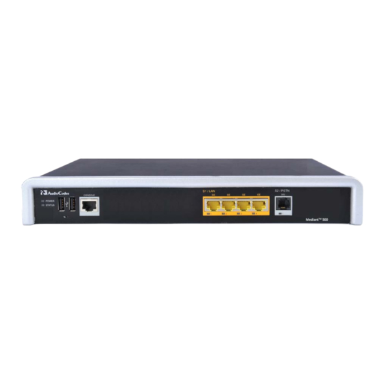
Front Panel Description This section describes the device's front panel. 3.2.1 Ports and Buttons The device's front panel is shown in the figure below and described in the subsequent table. Figure 3-1: Front Panel Session Border Controllers Mediant 500 E-SBC... -
Page 16: Led Descriptions
Mediant 500 E-SBC Table 3-2: Front Panel Description Item # Label Description POWER / STATUS LEDs indicating the status of the power and reboot/initialization. For more information, see Section 3.2.2 on page 16. Reset pinhole button for resetting the device and optionally, for restoring the device to factory defaults. -
Page 17: Lan Interface Led
The POWER LED indicates the power supply status, as described in the table below. Table 3-6: POWER LED Description Description Color State Green Power is received by the device. No power received by the device. Session Border Controllers Mediant 500 E-SBC... -
Page 18: Rear Panel Description
Mediant 500 E-SBC Rear Panel Description The device's rear panel is shown in the figure below and described in the subsequent table. Figure 3-2: Rear Panel Table 3-7: Rear Panel Description Item # Label Description Protective earthing screw. I / 0 Power switch (O is off;... -
Page 19: Mounting The Device
1 = Mounted anti-slide rubber feet • 2 = Anti-slide groove Flip the device over again so that it rests on the rubber feet and place it in the required position on a desktop. Session Border Controllers Mediant 500 E-SBC... -
Page 20: 19-Inch Rack Mounting
Mediant 500 E-SBC 19-Inch Rack Mounting The device can be installed in a standard 19-inch rack by implementing one of the following mounting methods: Placing it on a pre-installed shelf in a 19-inch rack – see Section 4.2.1 on page ... -
Page 21: Using Mounting Brackets
Two mounting brackets are provided: Left mounting bracket: Figure 4-2: Left Mounting Bracket Right mounting bracket with hole for looping through an optional cable tie (not supplied) for securing cables: Figure 4-3: Right Mounting Bracket Session Border Controllers Mediant 500 E-SBC... -
Page 22: Figure 4-4: Attaching The Mounting Brackets
Mediant 500 E-SBC To mount the device in a 19-inch rack using mounting brackets: Attach the two mounting brackets (supplied) to each side of the device's chassis, using the supplied screws, as shown in the figure below: Figure 4-4: Attaching the Mounting Brackets •... -
Page 23: Cabling The Device
(located on the rear panel), using the supplied washer. Connect the other end of the strap to a protective earthing. This should be in accordance with the regulations enforced in the country of installation. Figure 5-1: Earthing the Device Session Border Controllers Mediant 500 E-SBC... -
Page 24: Connecting To The Lan
Mediant 500 E-SBC Connecting to the LAN The device provides up to four Gigabit Ethernet (10/100/1000Base-T) ports for connection to the LAN (e.g., computers, switches, and IP phones). These ports support half- and full- duplex modes, auto-negotiation, and straight or crossover cable detection. -
Page 25: Connecting To An Isdn Pri (E1/T1) Trunk
To connect the E1/T1 trunk interface: Connect the E1/T1 trunk cable to the device’s E1/T1 port. Connect the other end of the trunk cable to your PBX/PSTN switch. Figure 5-4: Cabling E1/T1 Port Session Border Controllers Mediant 500 E-SBC... -
Page 26: Connecting The Serial Interface To A Pc
Mediant 500 E-SBC Connecting the Serial Interface to a PC The device provides an RS-232 serial interface port on its front panel. The serial cable adapter used for connecting the RS-232 interface is shown below: Figure 5-5: RS-232 Cable Adapter... -
Page 27: Connecting A Usb Storage Device
Connect the USB storage device to one of the USB ports located on the front panel. Figure 5-7: Connecting a USB Storage Device Note: Only a single USB storage (formatted to FAT/FAT32) operation is supported at any given time. Session Border Controllers Mediant 500 E-SBC... -
Page 28: Connecting To The Power Supply
Use only the AC power cord that is supplied with the device. ご注 意 本製品に添付の電源ケーブルは、Mediant 500 E-SBC に専用設計されているため、汎用 性がありません. 本電源ケーブルを他の機器に使用されないよう、ご注意ください. To connect the device to the power supply: Connect the line socket of the AC power cord (supplied) to the device's AC power socket (labeled 100-240V~50-60 Hz 0.8A), located on the rear panel. - Page 29 Hardware Installation Manual 5. Cabling the Device This page is intentionally left blank. Session Border Controllers Mediant 500 E-SBC...
- Page 30 International Headquarters Contact us: www.audiocodes.com/info Website: www.audiocodes.com Document #: LTRT-10391...