Table of Contents
Advertisement
Quick Links
Download this manual
See also:
User Manual
Advertisement
Table of Contents

Related Manuals for AudioCodes Mediant 4000B SBC


Summary of Contents for AudioCodes Mediant 4000B SBC
- Page 1 Hardware Installation Manual AudioCodes Mediant™ Family of Session Border Controllers (SBC) Mediant 4000B SBC...
-
Page 3: Table Of Contents
Replacing the SBC CPU Module ................50 Installing the MPM Modules ................... 52 Installing the OSN Server Modules ................ 54 Replacing the Fan Tray Modules ................56 Replacing the Power Supply Modules ..............58 Session Border Controllers Mediant 4000B SBC... - Page 4 Mediant 4000B SBC List of Figures Figure 3-1: Front Panel .......................... 16 Figure 3-2: Module Slot Assignment on Front Panel ................17 Figure 3-3: SBC CPU Module ........................ 18 Figure 3-4: SBC CPU Module Ports ...................... 18 Figure 3-5: SBC CPU Module LEDs ...................... 19 Figure 3-6: MPM LEDs (e.g.
- Page 5 Table 5-1: RJ-45 Connector Pinouts ..................... 38 Table 5-2: HDMI Type-D Connector Pinouts ..................43 Table 5-3: RJ-45 Connector Pinouts for Gigabit Ethernet Interface on OSN4 Module ......45 Table 5-4: Power Specifications ......................46 Session Border Controllers Mediant 4000B SBC...
- Page 6 Mediant 4000B SBC This page is intentionally left blank. Hardware Installation Manual Document #: LTRT-41749...
- Page 7 Customer Support Customer technical support and services are provided by AudioCodes or by an authorized AudioCodes Service Partner. For more information on how to buy technical support for AudioCodes products and for contact information, please visit our Web site at www.audiocodes.com/support.
- Page 8 Mediant 4000B SBC Related Documentation Manual Name SIP Release Notes Mediant 4000 SBC User's Manual Notes and Warnings Warning: The device is an INDOOR unit and thus, must be installed ONLY indoors. In addition, Ethernet port interface cabling must be routed only indoors and must not exit the building.
- Page 9 Document Revision Record LTRT Description 41743 Initial document release for Version 7.0. 41745 Map of slots on front panel was updated. 41746 Front-panel description regarding slot numbers updated; module slot assignment updated. 41748 Output ratings removed. Session Border Controllers Mediant 4000B SBC...
- Page 10 Mediant 4000B SBC Documentation Feedback AudioCodes continually strives to produce high quality documentation. If you have any comments (suggestions or errors) regarding this document, please fill out the Documentation Feedback form on our Web site at http://www.audiocodes.com/downloads. Hardware Installation Manual...
-
Page 11: Introduction
Introduction This document provides a hardware description of the Mediant 4000B (hereafter referred to as device) and step-by-step procedures for cabling the device. Note: For configuring the device, refer to the device's User’s Manual. Session Border Controllers Mediant 4000B SBC... - Page 12 Mediant 4000B SBC This page is intentionally left blank. Hardware Installation Manual Document #: LTRT-41749...
-
Page 13: Unpacking The Device
Adjustable Rear-Rack Mounting Bracket Kit for mounting the chassis in a 19-inch rack • Two-meter serial interface cable adaptor. Check, retain and process any documents. If there are any damaged or missing items, notify your AudioCodes sales representative. Session Border Controllers Mediant 4000B SBC... - Page 14 Mediant 4000B SBC This page is intentionally left blank. Hardware Installation Manual Document #: LTRT-41749...
-
Page 15: Physical Description
Weight Approx. 7.4 kg (16.3 lbs.) with basic hardware configuration (i.e., without MPM and OSN server modules). For chassis weight of specific hardware configurations, please contact your AudioCodes sales representative. Operational: 0 to 40°C (32 to 104°F) Environmental ... -
Page 16: Front Panel Description
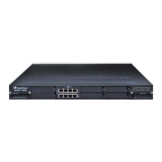
Mediant 4000B SBC Front Panel Description The device's front panel is shown in the figure below and described in the subsequent table. Figure 3-1: Front Panel Note: The figure above provides only an example of the Mediant 4000B. The modules housed in your Mediant 4000B may be slightly different, depending on the ordered hardware configuration (e.g., Media Processing Module / MPM and OSN server... -
Page 17: Module Slot Assignment
3. Physical Description 3.2.1 Module Slot Assignment The slot assignments on the front panel for the various modules per hardware configuration are shown in the figure below: Figure 3-2: Module Slot Assignment on Front Panel Session Border Controllers Mediant 4000B SBC... -
Page 18: Sbc Cpu Module
Mediant 4000B SBC 3.2.2 SBC CPU Module The SBC CPU module provides the main functionalities of the device. These functionalities include the central processor unit (CPU), Ethernet port interfaces, serial interface, and a reset pinhole button. Figure 3-3: SBC CPU Module For replacing the SBC CPU module, see Section on page 50. -
Page 19: Led Description
During booting up state. Booting up phase / fault detected in module. Green Normal operation. During booting up state. Green Application running in Standalone state. Flashing Application running in High Availability (HA) Active state. Session Border Controllers Mediant 4000B SBC... -
Page 20: Media Processing (Mpm) Module
Mediant 4000B SBC Item # Color State Description Yellow Application is starting Boot / synchronizing Flashing Application is running in HA Redundant state. Out of service. Normal operation. Left Green Ethernet link established. Ethernet Flashing Data is being received or transmitted Port LED (activity) on the Ethernet port. -
Page 21: Figure 3-6: Mpm Leds (E.g. Mpm12B)
If this occurs, push on the handle until it is flush with the chassis (i.e. module locked in the slot). Module handle is locked (i.e., module is securely installed in the slot). Session Border Controllers Mediant 4000B SBC... -
Page 22: Osn Server Modules
Mediant 4000B SBC 3.2.4 OSN Server Modules The OSN4 server modules are customer-ordered items. The OSN server consists of two modules: OSN4 - central processing unit (CPU), RAM, and port interfaces HDMX - hard-disk drive (HDD or SSD) providing storage capacity... -
Page 23: Figure 3-8: Osn4 Module Leds
End of reset: LED #1 remains on (solid green); all other LEDs off. 3.2.4.1.2 LED Description The LEDs of the OSN4 module are shown in the figure below and described in the subsequent table. Figure 3-8: OSN4 Module LEDs Session Border Controllers Mediant 4000B SBC... -
Page 24: Hdmx Module
Mediant 4000B SBC Table 3-8: OSN4 Module LED Description Item Color State Description Green Flashing Firmware (BIOS) application active, payload (x86) in sleep. Firmware (BIOS) application active, payload (x86) active. Out-of-service indicator due to hardware failure. Normal operation. Green Solid Valid Ethernet link (cable connection) established. -
Page 25: Table 3-9: Hdmx Module Led Description
No power received by module. Hard disk drive in use (active). Hard disk drive not in use. Blue Module can be extracted from chassis slot once dismounted from the OSN operating system. Module correctly inserted in chassis slot Session Border Controllers Mediant 4000B SBC... -
Page 26: Fan Tray Module
Mediant 4000B SBC 3.2.5 Fan Tray Module The device provides two Fan Tray modules, located on either side of the chassis. Each module contains five integrated fans which cool the device's internal components. The Fan Tray module located on the left side of the chassis draws air from the outside through its' perforated grill. -
Page 27: Rear Panel Description
Power status LED for indicating the status of the Power Supply module. For more information, see Section 3.3.1 on page 28. Extraction-handle for removing the Power Supply module. 100-240V~7A AC power supply inlet (100-240V~7A, 50-60 Hz) of 50-60Hz Power Supply module. Session Border Controllers Mediant 4000B SBC... -
Page 28: Power Supply Modules
Mediant 4000B SBC 3.3.1 Power Supply Modules The chassis houses two Power Supply modules for providing power load sharing and AC power redundancy in case of failure of one of the Power Supply modules. Each module is associated with an AC power inlet located on the rear panel of the chassis for connection to an electrical power outlet. -
Page 29: Mounting The Device
Peel off the adhesive, anti-slide rubber feet (supplied) and stick one in each anti-slide groove. Flip the device over again so that it rests on its underside with the rubber feet in contact with the surface. Session Border Controllers Mediant 4000B SBC... -
Page 30: 19-Inch Rack Mounting
Mediant 4000B SBC 19-Inch Rack Mounting The device is designed to fit into a 19-inch industrial rack of 1 rack-unit height (1U). You can mount it in the rack using any one of the following mounting options: (Recommended) Mounting the chassis on a pre-installed shelf in a 19-inch rack – see Section 4.2.1... -
Page 31: Mounting In A 19-Inch Rack Using Pre-Installed Rack Shelf
Secure the front-mounting brackets to the rack posts using standard 19-inch rack bolts (not supplied). This step is crucial in that it prevents the chassis from accidently sliding off the shelf. Session Border Controllers Mediant 4000B SBC... -
Page 32: Mounting In A 19-Inch Rack Using Front And Rear Brackets
Mediant 4000B SBC 4.2.2 Mounting in a 19-inch Rack using Front and Rear Brackets The device can be mounted in a 19-inch rack by attaching the chassis directly to the rack frame, using both front- and rear-mounting brackets. The device is shipped with two types of rear-mounting kits, each suited for a specific rack depth (60 or 80 cm): ... -
Page 33: Figure 4-3: Rear-Mounting Brackets Attached To Rear-Rack Posts (60 Cm)
See the figure below for correct orientation of the brackets when attaching them to the posts. Figure 4-3: Rear-Mounting Brackets Attached to Rear-Rack Posts (60 cm) Figure 4-4: Rear-Mounting Brackets Attached to Rear-Rack Posts (80 cm) Session Border Controllers Mediant 4000B SBC... -
Page 34: Figure 4-5: Attaching Rear-Mounting Flange To Chassis' Rear-Side Mounting Holes (60 Cm)
Mediant 4000B SBC Attach the rear-mounting flanges to the rear sides of the chassis, using three screws (supplied) per flange. Figure 4-5: Attaching Rear-Mounting Flange to Chassis' Rear-Side Mounting Holes (60 cm) Figure 4-6: Attaching Rear-Mounting Flange to Chassis' Rear-Side Mounting Holes (80 cm) With two people, lift the chassis into the rack from the front of the rack. -
Page 35: Figure 4-9: Fastening Rear-Mounting Flange To Rear-Mounting Bracket (60 Cm)
For 80-cm rear mounting, up to two screws can be used to secure the flange to the rear-mounting bracket (if required). Figure 4-9: Fastening Rear-Mounting Flange to Rear-Mounting Bracket (60 cm) Figure 4-10: Fastening Rear-Mounting Flange to Rear-Mounting Bracket (80 cm) Session Border Controllers Mediant 4000B SBC... -
Page 36: Figure 4-11: Front-Mounting Brackets Flush And Aligned With Front-Rack Posts (60 Cm)
Mediant 4000B SBC Hold the chassis for support while the second person positions the chassis so that the front-mounting brackets are flush against the front-rack posts and the holes of the front-mounting brackets align with the holes on the front-rack posts. -
Page 37: Cabling The Device
This section describes how to cable the device: Connecting to the LAN – see Section on page Connecting to a computer for serial communication – see Section on page Connecting to power – see Section on page Session Border Controllers Mediant 4000B SBC... -
Page 38: Connecting The Ethernet Ports To The Lan
Mediant 4000B SBC Connecting the Ethernet Ports to the LAN The cabling specifications and procedure for connecting the device to the LAN is as follows: Cable: Straight-through, Category (Cat) 5, 5e or 6 cable Connector: Standard RJ-45 ... -
Page 39: Deployment Of A Standalone Device
Each port in the Ethernet Group (port pair) must be connected to a different switch (but in the same subnet). √ Ports with the same MAC address (e.g., GE 1-4 ports) must each be connected to a different Layer-2 switch (as the ports share the same MAC address). Session Border Controllers Mediant 4000B SBC... -
Page 40: Deployment Of Two Devices For High Availability
Mediant 4000B SBC The following example shows an Ethernet Group comprised of ports 5 and 6, where Port 5 is connected to the main network ("LAN #1") and Port 6 to the redundant network ("LAN #2"). Upon connectivity failure with LAN #1 through Port 5, the device connects to the redundant LAN #2 through Port 6. -
Page 41: Connecting The Serial Interface To A Computer
Connect the DB-9 connector labeled "P1" (red), at the other end of the cable, to the RS-232 communication port on your computer. Notes: • The RS-232 port is not intended for permanent connection. • The DB-9 connector labeled "P2" is used only for debugging. Session Border Controllers Mediant 4000B SBC... -
Page 42: Connecting The Osn Server
For specifications of the OSN server, including ports and LEDs, see Section 3.2.4 page 22. • Optional drivers for the OSN server modules can be downloaded from AudioCodes Web site (for registered users only) at http://www.audiocodes.com/downloads. 5.3.1 Cabling for Installing Operating System The OSN server can run on Linux™... -
Page 43: Figure 5-7: Cabling Osn4 Module For Installing Operating System
Table 5-2: HDMI Type-D Connector Pinouts Signal TMDS Data2+ TMDS Data2 Shield TMDS Data2- TMDS Data1+ TMDS Data1 Shield TMDS Data1- TMDS Data0+ TMDS Data0 Shield TMDS Data0- TMDS Clock+ TMDS Clock Shield TMDS Clock- Session Border Controllers Mediant 4000B SBC... -
Page 44: Cabling For Initial Installation Of Third-Party Applications
Mediant 4000B SBC Signal Utility/HEAC+ DDC/CEC/HEAC Ground +5 V Power Hot Plug Detect/HEAC 5.3.2 Cabling for Initial Installation of Third-Party Applications Once you have installed an operating system, you can connect to the OSN server in order to install and configure your third-party application (e.g., IP PBX). For this you can connect to the OSN server using the following local connectivity methods: ... -
Page 45: Cabling For Remote Connectivity (Post-Initial Setup)
The RJ-45 connector pinouts for the Gigabit Ethernet interface are listed in the table below: Table 5-3: RJ-45 Connector Pinouts for Gigabit Ethernet Interface on OSN4 Module 100Base-Tx 1000Base-T Signal Signal Function BI_DA+ BI_DA- BI_DB+ BI_DC+ BI_DC- BI_DB- BI_DD+ BI_DD- Session Border Controllers Mediant 4000B SBC... -
Page 46: Connecting To Power
Mediant 4000B SBC Connecting to Power The procedure below describes how to connect the device to the power supply. Table 5-4: Power Specifications Item Description Power Supply Two hot swappable, power supply modules for power load sharing and AC power redundancy in case of failure of one of the modules. -
Page 47: Figure 5-10: Connecting To Power
Turn on the power at the power source (if required). Check that the POWER LED on each Power Supply module (front panel) is lit green, indicating that the device is receiving power. Session Border Controllers Mediant 4000B SBC... - Page 48 Mediant 4000B SBC This page is intentionally left blank. Hardware Installation Manual Document #: LTRT-41749...
-
Page 49: Hardware Maintenance
Attach the other end of the wrist strap (e.g., an alligator clip) to the ESD spring screw located on the rear panel of the chassis, as shown below. Figure 6-1: Connecting ESD Wrist Strap to Chassis ESD Lug Session Border Controllers Mediant 4000B SBC... -
Page 50: Replacing The Sbc Cpu Module
Mediant 4000B SBC Replacing the SBC CPU Module The procedure below describes how to replace the SBC CPU module. Warning: Before extracting the module, power off the device. To replace the SBC CPU module: Remove the module: Disconnect the power cord from the power sources, and then remove the power cord from the power connections on the two Power Supply modules. -
Page 51: Figure 6-4: Inserting Sbc Cpu Module
Figure 6-4: Inserting SBC CPU Module Push the module's handle until it clicks firmly in to engage the module with the slot rails. Connect all external interfacing cables to the module, as required. Session Border Controllers Mediant 4000B SBC... -
Page 52: Installing The Mpm Modules
Mediant 4000B SBC Installing the MPM Modules The procedure below describes how to install an MPM module into the chassis. Each MPM module occupies two standard AMC slots. Therefore, before installing an MPM module, you need to remove the blank AMC modules covering the slots. -
Page 53: Figure 6-6: Inserting Mpm Module
Figure 6-6: Inserting MPM Module Push the module's handle until it clicks firmly in to engage the module with the slot rails. Power up the device. Session Border Controllers Mediant 4000B SBC... -
Page 54: Installing The Osn Server Modules
Mediant 4000B SBC Installing the OSN Server Modules The OSN server is a customer-ordered item. The procedure below describes how to install the OSN server modules (OSN and HDMX) in the chassis. Warning: Power off the device before installing the OSN modules. -
Page 55: Figure 6-8: Inserting Osn Module
Figure 6-9: Inserting HDMX Module Push the module's handle until it clicks firmly in to engage the module with the slot rails. Power up the device. Session Border Controllers Mediant 4000B SBC... -
Page 56: Replacing The Fan Tray Modules
Mediant 4000B SBC Replacing the Fan Tray Modules This section describes how to replace the Fan Tray module. It describes replacement of the Fan Tray module #1 (on left side of chassis), but it also applies to the Fan Tray module The Fan Tray module is hot-swappable and thus, can be replaced without powering down the device. -
Page 57: Figure 6-11: Extracting Fan Tray Module Using Handle
Fan Tray module to secure the module to the chassis. Verify that the newly installed Fan Tray module is receiving power and operating normally - the PWR LED on the module's front panel should be lit green. Session Border Controllers Mediant 4000B SBC... -
Page 58: Replacing The Power Supply Modules
Mediant 4000B SBC Replacing the Power Supply Modules This section describes how to replace the Power Supply module. It describes replacement of the Power Supply module #1 (on left side of chassis), but it also applies to the Power Supply module #2. -
Page 59: Figure 6-13: Extracting Power Supply Module
Using the module's handle, gently push the module into the slot until it has engaged with the chassis backplane. Tighten the two captive screws on the front panel of the module to secure the module to the chassis. You can use a Phillips or flathead screwdriver. Session Border Controllers Mediant 4000B SBC... - Page 60 International Headquarters AudioCodes Inc. 1 Hayarden Street, 27 World’s Fair Drive, Airport City Somerset, NJ 08873 Lod 7019900, Israel Tel:+1-732-469-0880 Tel: +972-3-976-4000 Fax:+1-732-469-2298 Fax: +972-3-976-4040 Contact us: www.audiocodes.com/info www.audiocodes.com Website: Document #: LTRT-41749...