Siemens SIMATIC ET 200SP Manual
Hide thumbs
Also See for SIMATIC ET 200SP:
- System manual (320 pages) ,
- Manual (270 pages) ,
- Operating instructions manual (166 pages)
Table of Contents
Advertisement
Advertisement
Table of Contents

Related Manuals for Siemens SIMATIC ET 200SP


Summary of Contents for Siemens SIMATIC ET 200SP
- Page 2 ___________________ Technology module TM Pulse 2x24V Preface (6ES7138‑6DB00‑0BB1) ___________________ Documentation guide ___________________ SIMATIC Product overview ___________________ Modes and Functions ET 200SP Technology module TM Pulse 2x24V ___________________ (6ES7138‑6DB00‑0BB1) Connecting ___________________ Configuring Manual ___________________ Program control and feedback interface ___________________ Interrupts/diagnostic messages ___________________ Technical specifications...
- Page 3 Note the following: WARNING Siemens products may only be used for the applications described in the catalog and in the relevant technical documentation. If products and components from other manufacturers are used, these must be recommended or approved by Siemens. Proper transport, storage, installation, assembly, commissioning, operation and maintenance are required to ensure that the products operate safely and without any problems.
-
Page 4: Preface
Siemens recommends strongly that you regularly check for product updates. For the secure operation of Siemens products and solutions, it is necessary to take suitable preventive action (e.g. cell protection concept) and integrate each component into a holistic, state-of-the-art industrial security concept. - Page 5 Siemens accepts no liability for the use of the open source software over and above the intended program sequence, or for any faults caused by modifications to the software.
-
Page 6: Table Of Contents
Table of contents Preface ..............................4 Documentation guide ..........................8 Product overview ............................. 10 Properties ..........................10 Modes and Functions ..........................14 Overview ..........................14 Pulse output (single pulse) mode ................... 17 Pulse width modulation (PWM) mode ..................25 Pulse train mode ........................36 On/Off-delay mode ......................... - Page 7 Table of contents 5.4.5 Channel parameters ......................103 5.4.5.1 Operating mode ........................103 5.4.5.2 Reaction to CPU STOP ......................103 5.4.5.3 Diagnostics ........................... 105 5.4.5.4 Parameter (Channel parameters) ..................106 5.4.6 I/O addresses ........................109 Program control and feedback interface ....................110 TM Pulse 2x24V control interface ..................
-
Page 8: Documentation Guide
Table 1- 1 Documentation for TM Pulse 2x24V technology module Topic Documentation Most important contents System description System manual Application planning • ET 200SP Distributed I/O System Installation • (https://support.industry.siemens.com/cs/mdm Connecting • /58649293?c=76156021003&t=1&s=BaseUnit &lc=en-US) Commissioning • Device manuals Connecting • Interface Module Interrupts, diagnostics, •... - Page 9 Parameter settings • ET with STEP 7 V13 SP1&lc=en-US) Function manual SIMATIC manuals All current manuals for the SIMATIC products are available for download free of charge from the Internet (https://support.industry.siemens.com/cs/?lc=en-US). Technology module TM Pulse 2x24V (6ES7138‑6DB00‑0BB1) Manual, 09/2015, A5E35061186-AA...
-
Page 10: Product Overview
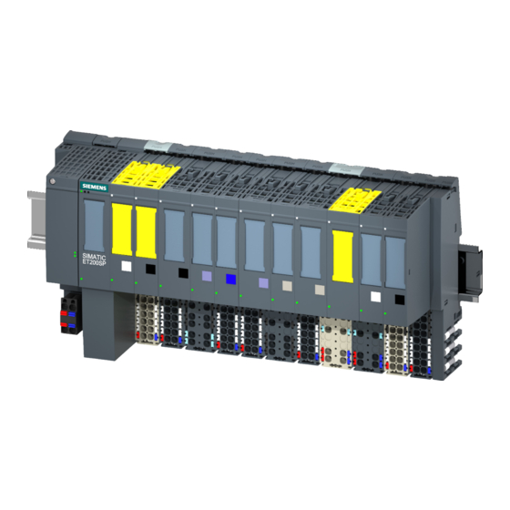
Product overview Properties Article number 6ES7138-6DB00-0BB1 View of the module Figure 2-1 View of the TM Pulse 2x24V module Technology module TM Pulse 2x24V (6ES7138‑6DB00‑0BB1) Manual, 09/2015, A5E35061186-AA... - Page 11 Product overview 2.1 Properties Properties The TM Pulse 2x24V technology module has the following properties: ● 2 pulse output channels with up to 2 A output current per channel – One-channel operation: The two channels are merged together into one logical channel and are connected in parallel to generate pulse signals with up to 4 A output current.
- Page 12 Product overview 2.1 Properties Operating modes ● Pulse output: output a single pulse with variable pulse duration and On-delay. ● Pulse width modulation (PWM): – Output a frequency with a defined period duration and variable ratio of pulse width to period duration (duty cycle).
- Page 13 ● TIA Portal V13 + SP1 with HSP 0131 (Hardware Support Package from the Internet) ● STEP 7 version V5.5 + SP4 with HSP 0240 ● GSD file links: – PROFIBUS GSD files (https://support.industry.siemens.com/cs/document/73016883?dti=0&lc=en-US) – PROFINET GSD files (https://support.industry.siemens.com/cs/document/57138621?dti=0&lc=en-US) Firmware update Firmware updates can be downloaded to the memory of the TM Pulse 2x24V module by means of the STEP 7 TIA Portal software or the HW Config software.
-
Page 14: Modes And Functions
Modes and Functions Overview Modes and functions The TM Pulse 2x24V has two channels. You can assign a different mode for each channel. Configuration of the operating mode is made using the TIA Portal or HW Config. You can select one of six operating modes: ●... - Page 15 Modes and Functions 3.1 Overview ● The TM Pulse 2x24V provides module diagnostics and channel error detection. Figure 3-1 Dual channel operation Figure 3-2 Single channel operation Technology module TM Pulse 2x24V (6ES7138‑6DB00‑0BB1) Manual, 09/2015, A5E35061186-AA...
- Page 16 Modes and Functions 3.1 Overview Interfaces to the control program and the process under control The TM Pulse 2x24V has the following I/O BaseUnit pin connections to the process under control: Channel 0: ● DI0.0 (digital input 0) ● DQ0.A and DQ0.B (digital output 0) –...
-
Page 17: Pulse Output (Single Pulse) Mode
Modes and Functions 3.2 Pulse output (single pulse) mode Pulse output (single pulse) mode Definition After the assigned On-delay time expires, the TM Pulse 2x24V outputs a pulse at the DQn.A digital output (output sequence) for the pulse duration that you set. Pulse diagram Figure 3-3 Pulse output mode output sequence using optional HW enable signal to start the output sequence... - Page 18 Modes and Functions 3.2 Pulse output (single pulse) mode Starting the output sequence Your control program must issue the enable for the output sequence, using the software enable (SW_ENABLE 0 → 1). The STS_SW_ENABLE feedback bit indicates that a software enable is pending in the TM Pulse 2x24V.
- Page 19 Modes and Functions 3.2 Pulse output (single pulse) mode Canceling the output sequence Disabling the software enable (SW_ENABLE = 1 → 0) cancels the current output sequence and the last period duration is not completed. STS_ENABLE and the DQn.A digital output are immediately reset to 0.
- Page 20 Modes and Functions 3.2 Pulse output (single pulse) mode Setting and changing the On-delay ● Permanent update The On-delay can be controlled permanently using the control interface. The MODE_SLOT bit has to be 1 (permanent-update); LD_SLOT must have the value 2 (for On-delay).
- Page 21 Modes and Functions 3.2 Pulse output (single pulse) mode Pulse output parameters Pulse output parameter Meaning Value Range Default Mode 0 = Set the Pulse output operating mode. 0 = Pulse output 1 = Pulse width modulation 2 = Pulse train 3 = On/Off-delay 4 = Frequency output 5 = DC Motor...
- Page 22 Modes and Functions 3.2 Pulse output (single pulse) mode Control and feedback signals for Pulse output mode Control interface: Offset to the start address Parameter Meaning Channel 0 Channel 1 Bytes 0 to 3 Bytes 12 to 15 OUTPUT_VALUE Pulse duration: the time that the DQn.A digital output remains set after the On-delay time expires.
- Page 23 Modes and Functions 3.2 Pulse output (single pulse) mode Feedback interface: Offset to the start address Parameter Meaning Channel 0 Channel 1 Byte 0: Bit 0 Byte 8: Bit 0 ERR_PWR Bit 0 Indicates under voltage on the Power supply. Note that the bit is not set if the voltage is not present.
- Page 24 Modes and Functions 3.2 Pulse output (single pulse) mode Feedback interface: Offset to the start address Parameter Meaning Channel 0 Channel 1 Byte 2: Bit 1 Byte 10: Bit 1 STS_DQA Bit 1 Indicates the signal level at the DQn.A digital output. 0 on DQn.A digital output 1 on DQn.A digital output Byte 2: Bit 2...
-
Page 25: Pulse Width Modulation (Pwm) Mode
Modes and Functions 3.3 Pulse width modulation (PWM) mode Pulse width modulation (PWM) mode Definition You control the pulse width duty cycle with the control interface field OUTPUT_VALUE. The TM Pulse 2x24V generates continuous pulses based on this value. The OUTPUT_VALUE control interface field determines the duty cycle (pulse duration/period duration) for PWM. - Page 26 Modes and Functions 3.3 Pulse width modulation (PWM) mode Starting the output sequence Your control program must issue the enable for the output sequence, using the software enable (SW_ENABLE 0 → 1). The STS_SW_ENABLE feedback bit indicates the software enable pending at the TM Pulse 2x24V.
- Page 27 Modes and Functions 3.3 Pulse width modulation (PWM) mode Software enable Function DI Hardware enable Digital output DQn.A STS_ENABLE Output sequence SW_ENABLE parameter (DIn.0 digital input) (when TM_CTRL_DQ = 1) HW_ENABLE or Any state 0, if On-delay is not expired or you are in the Input interpulse time 1, if On-delay is expired and during the pulse...
- Page 28 Modes and Functions 3.3 Pulse width modulation (PWM) mode Note If Dithering is activated without current control, then the minimum pulse duration and minimum inter-pulse period are used by the module. In this case, the superimposed Dithering is reduced so the effective pulse duration fits in the allowed range. Setting and changing the pulse duty cycle OUTPUT_VALUE assigns the duty cycle for the current period duration.
- Page 29 Modes and Functions 3.3 Pulse width modulation (PWM) mode For more details about SLOT parameter handling, see "Slot parameter handling (control interface) (Page 113)". Isochronous mode General information is available in the "Function: Isochronous mode (Page 86)" topic. In isochronous mode, the output sequence is synchronized with the moment T .
- Page 30 Modes and Functions 3.3 Pulse width modulation (PWM) mode ● Example 2: The period duration 3333 μs is less than the application cycle time 10 ms (10000 μs). ● Example 3: The period duration 30000 μs is greater than the application cycle time 10 ms (10000 μs) Note Isochronous PWM operation...
- Page 31 Modes and Functions 3.3 Pulse width modulation (PWM) mode Setting the minimum pulse duration and minimum inter-pulse duration You assign the minimum pulse duration and the minimum inter-pulse duration as a DWord number value between 0 and 85,000,000 μs using the "Minimum pulse duration" channel parameter configuration.
- Page 32 Modes and Functions 3.3 Pulse width modulation (PWM) mode Parameters of PWM operating mode Parameter Meaning Value range Default Operating mode 1 = Set the PWM operating mode. 0 = Pulse output 1 = Pulse width modulation 2 = Pulse train 3 = On/Off-delay 4 = Frequency output 5 = DC Motor...
- Page 33 Modes and Functions 3.3 Pulse width modulation (PWM) mode Control and feedback signals for PWM mode Control interface Offset to the start address Parameter Meaning Channel 0 Channel 1 Bytes 0 to 3 Bytes 12 to OUTPUT_VALUE The OUTPUT_VALUE determines the duty cycle (pulse duration/period duration ratio) within a period (pulse width modulation).
- Page 34 Modes and Functions 3.3 Pulse width modulation (PWM) mode Control interface Offset to the start address Parameter Meaning Channel 0 Channel 1 Byte 9: Bit 4 Byte 21: Bit 4 SET_DQB Bit 4 Controls the value of the digital output DQn.B, if TM_CTRL_DQ = 0 and if SET_DQA is cleared.
- Page 35 Modes and Functions 3.3 Pulse width modulation (PWM) mode Feedback interface: Offset to the start address Parameter Meaning Channel 0 Channel 1 Byte 1: Bit 5 Byte 9: Bit 5 STS_SW_ENABLE Bit 5 Indicates the status of SW_ENABLE (control interface). SW_ENABLE cleared SW_ENABLE set Byte 2: Bit 0...
-
Page 36: Pulse Train Mode
Modes and Functions 3.4 Pulse train mode Pulse train mode Definition On expiration of the assigned On-delay, the TM Pulse 2x24V outputs the number of pulses you assigned as a pulse train (output sequence). The period duration and pulse duration can be adjusted. - Page 37 Modes and Functions 3.4 Pulse train mode Starting the output sequence Your control program must issue the enable for the output sequence, using the software enable (SW_ENABLE 0 → 1). The STS_SW_ENABLE feedback bit indicates the software enable pending at the TM Pulse 2x24V.
- Page 38 Modes and Functions 3.4 Pulse train mode Truth table Software enable Function DI Hardware enable Digital output DQn.1 STS_ENABLE Output sequence SW_ENABLE parameter (DIn.0 digital input) (when TM_CTRL_DQ = 1) HW_ENABLE 0 → 1 and remains 1 0, if On-delay > 0 0 →...
- Page 39 Modes and Functions 3.4 Pulse train mode Setting and changing the period duration ● Permanent update The period duration can be controlled permanently using the control interface. The MODE_SLOT bit has to be set ('1' means permanent update); LD_SLOT has to have the value 1 (for Period duration).
- Page 40 Modes and Functions 3.4 Pulse train mode Setting and changing the duty cycle The range of the duty cycle parameter is selected using the "Output format" parameter. The TM Pulse 2x24V uses this assigned duty cycle value to calculate the pulse duration. If the number value you assign exceeds the upper limit, then a duty cycle of 100% of the period duration is used and this action does not cause an error.
- Page 41 Modes and Functions 3.4 Pulse train mode Current measurement Current measurement is available in Pulse train mode. Your control program can use current measurement for control and diagnostic purposes. For more information, refer to Function: Current measurement (Page 76). Parameters for Pulse train operating mode Parameter Meaning Value range...
- Page 42 Modes and Functions 3.4 Pulse train mode Parameter Meaning Value range Default On-delay The time from the start of the output 0 μs to 85,000,000 μs 0 μs sequence to the output of the pulse train. You can change the On-delay in your control program using the SLOT parameter.
- Page 43 Modes and Functions 3.4 Pulse train mode Control and feedback signals for Pulse train operating mode Control interface Offset to the start address Parameter Meaning Channel 0 Channel 1 Bytes 0 to 3 Bytes 12 to 15 OUTPUT_VALUE Assign the number of pulses to the OUTPUT_VALUE as a DWord number value 0 to 4,294,967,295 (2 -1).
- Page 44 Modes and Functions 3.4 Pulse train mode Feedback interface: Offset to the start address Parameter Meaning Channel 0 Channel 1 Byte 0: Bit 0 Byte 8: Bit 0 ERR_PWR Bit 0 Indicates under voltage on the Power supply. Note that the bit is not set if the voltage is not present.
- Page 45 Modes and Functions 3.4 Pulse train mode Feedback interface: Offset to the start address Parameter Meaning Channel 0 Channel 1 Byte 2: Bit 2 Byte 10: Bit 2 STS_DQB Bit 2 Indicates the signal level at the DQn.B digital output. 0 at the DQn.B digital output 1 at the DQn.B digital output Byte 2: Bit 3...
-
Page 46: On/Off-Delay Mode
Modes and Functions 3.5 On/Off-delay mode On/Off-delay mode Definition The signal pending at the TM Pulse 2x24V DIn.0 digital input is output with an assigned On/Off-delay at the DQn.A digital output. Pulse diagram SW_ENABLE is set, while DIn.0 digital input = 0: Figure 3-7 Output sequence On/Off-delay (at the start DIn.0 digital input = 0) Technology module TM Pulse 2x24V (6ES7138‑6DB00‑0BB1) - Page 47 Modes and Functions 3.5 On/Off-delay mode SW_ENABLE is set, while DIn.0 digital input = 1: If SW_ENABLE is set while DIn.0 digital input = 1, the first edge of a digital input (falling edge) is ignored. Figure 3-8 Output sequence On/Off-delay (at the start DIn.0 digital input = 1) Technology module TM Pulse 2x24V (6ES7138‑6DB00‑0BB1) Manual, 09/2015, A5E35061186-AA...
- Page 48 Modes and Functions 3.5 On/Off-delay mode Starting the output sequence Your control program must issue the enable for the output sequence, using the software enable (SW_ENABLE 0 → 1). The STS_SW_ENABLE feedback bit indicates the software enable pending at the TM Pulse 2x24V.
- Page 49 Modes and Functions 3.5 On/Off-delay mode Truth Table Software enable DIn.0 digital input DQn.A digital output STS_ENABLE Output sequence SW_ENABLE (when TM_CTRL_DQ = 1) 0 → 1 and remains 1 0, if On-delay > 0 Start during the input delay 1, if On-delay = 0 1 →...
- Page 50 Modes and Functions 3.5 On/Off-delay mode Response of the TM Pulse 2x24V to a pulse duration that is too short: ● ERR_PULSE is set. ● The current On-delay is cleared. ● The Off-delay is not started. ● The signal level at the DQn.A digital output remains at 0. ERR_PULSE is cleared at the next positive edge on the DIn.0 digital input.
- Page 51 Modes and Functions 3.5 On/Off-delay mode ERR_PULSE is cleared with the next negative edge on the DIn.0 digital input. Figure 3-10 DIn.0 inter-pulse duration too short Retriggering the current On-delay The TM Pulse 2x24V starts a new On-delay on the positive edge on the DIn.0 digital input if: On-delay >...
- Page 52 Modes and Functions 3.5 On/Off-delay mode Retriggering the current Off-delay The TM Pulse 2x24V starts a new Off-delay on the negative edge on the DIn.0 digital input if: Off-delay > pulse duration + inter-pulse duration The DQn.A digital output is only cleared if signal level 0 is present on the Dn.0I digital input longer than the Off-delay.
- Page 53 Modes and Functions 3.5 On/Off-delay mode Isochronous mode General information is available in Function: Isochronous mode (Page 86). Isochronous mode does not have any influence on the functionality of On/Off-delay operating mode. Parameters for On/Off-delay operating mode Parameter Meaning Value Range Default Mode 3 = Set the "On/Off-delay"...
- Page 54 Modes and Functions 3.5 On/Off-delay mode Control and feedback signals for On/Off-delay operating mode Control interface Offset to the start address Parameter Meaning Channel 0 Channel 1 Bytes 0 to 3 Bytes 12 to 15 OUTPUT_VALUE On-delay (DWord) 0 μs to 85,000,000 μs Bytes 4 to 7 Bytes 16 to 19 SLOT...
- Page 55 Modes and Functions 3.5 On/Off-delay mode Feedback interface: Offset to the start address Parameter Meaning Channel 0 Channel 1 Byte 0: Bit 0 Byte 8: Bit 0 ERR_PWR Bit 0 Indicates under voltage on the Power supply. Note that the bit is not set if the voltage is not present.
- Page 56 Modes and Functions 3.5 On/Off-delay mode Feedback interface: Offset to the start address Parameter Meaning Channel 0 Channel 1 Byte 2: Bit 0 Byte 8: Bit 0 STS_ENABLE Bit 0 Indicates an output sequence is running. Pulse output is not running Pulse output is running Byte 2: Bit 1 Byte 10: Bit 1...
-
Page 57: Frequency Output Mode
Modes and Functions 3.6 Frequency output mode Frequency output mode Definition This mode allows you to assign a frequency value at high frequencies more precisely than PWM period and Period duration. A square wave signal with an assigned frequency and a constant duty cycle of 50% is produced at the digital output of the TM Pulse 2x24V. - Page 58 Modes and Functions 3.6 Frequency output mode Starting the output sequence Your control program must issue the enable for the output sequence, using the software enable (SW_ENABLE 0 → 1). The STS_SW_ENABLE feedback bit indicates the software enable pending at the TM Pulse 2x24V.
- Page 59 Modes and Functions 3.6 Frequency output mode Truth table Software enable Function DI Hardware enable DQn.A digital output STS_ENABLE Output sequence SW_ENABLE parameter (DIn.0 digital input) (when TM_CTRL_DQ = 1) HW_ENABLE 0 → 1 and remains 1 0, if On-delay > 0 0 →...
- Page 60 Modes and Functions 3.6 Frequency output mode Setting and changing the On-delay ● Permanent update The On-delay can be controlled permanently using the control interface. MODE_SLOT bit has to be set (permanent-update); LD_SLOT must be the value 2 (for On-delay). Set the On-delay as a value between 0 μs and 85,000,000 μs in the field SLOT.
- Page 61 Modes and Functions 3.6 Frequency output mode Parameters of Frequency output operating mode Parameter Meaning Value range Default Mode 4 = Set the Frequency output oper- 0 = Pulse output ating mode. 1 = Pulse width modulation 2 = Pulse train 3 = On/Off-delay 4 = Frequency output 5 = DC Motor...
- Page 62 Modes and Functions 3.6 Frequency output mode Control interface Offset to the start address Parameter Meaning Channel 0 Channel 1 Byte 8: Bit 4 Byte 20: Bit 4 MODE_SLOT Bit 4 Mode for use of the field SLOT. Single-update mode Permanent-update mode Byte 9: Bit 0 Byte 21: Bit 0...
- Page 63 Modes and Functions 3.6 Frequency output mode Feedback interface: Offset to the start address Parameter Meaning Channel 0 Channel 1 Byte 0: Bit 0 Byte 8: Bit 0 ERR_PWR Bit 0 Indicates under voltage on the Power supply. Note that the bit is not set if the voltage is not present.
- Page 64 Modes and Functions 3.6 Frequency output mode Feedback interface: Offset to the start address Parameter Meaning Channel 0 Channel 1 Byte 2: Bit 2 Byte 10: Bit 2 STS_DQB Bit 2 Indicates the signal level at the DQn.B digital output. 0 on DQn.B digital output 1 on DQn.B digital output Byte 2: Bit 3...
-
Page 65: Dc Motor Mode
Modes and Functions 3.7 DC motor mode DC motor mode Definition Each channel has an A and a B output for connection to your DC motor load. The bipolar output switch and pulse width modulation lets your assign rotation direction and output voltage duty cycle. - Page 66 Modes and Functions 3.7 DC motor mode Starting the output sequence Your control program must issue the enable for the output sequence, using the software enable (SW_ENABLE 0 → 1). The STS_SW_ENABLE feedback bit indicates the software enable pending at the TM Pulse 2x24V.
- Page 67 Modes and Functions 3.7 DC motor mode Truth table Software enable Function DI Hardware enable Digital output DQn.A and STS_ENABLE Output sequence SW_ENABLE parameter (DIn.0 digital input) DQn.B HW_ENABLE 0 → 1 and remains 1 during If On-delay > 0: 0 →...
- Page 68 Modes and Functions 3.7 DC motor mode Setting and changing the pulse duty cycle and rotation direction OUTPUT_VALUE assigns the duty cycle and the direction for the current period duration. OUTPUT_VALUE is given as an S7 analog value, the sign gives the direction of the motor rotation ("+"...
- Page 69 Modes and Functions 3.7 DC motor mode Isochronous mode General information is available in the "Function: Isochronous mode" topic. In isochronous mode, the output sequence is synchronized with the moment T . The period duration is coordinated to the application cycle (the synchronous cycle, a multiple of the PROFINET cycle).
- Page 70 Modes and Functions 3.7 DC motor mode Parameters for DC motor operating mode Parameter Meaning Value range Default Operating mode 5 = Set the DC motor operating mode. 0 = Pulse output 1 = Pulse width modulation 2 = Pulse train 3 = On/Off-delay 4 = Frequency output 5 = DC Motor...
- Page 71 Modes and Functions 3.7 DC motor mode Control and feedback signals for DC motor mode Control interface Offset to the start address Parameter Meaning Channel 0 Channel 1 Bytes 0 to 3 Bytes 12 to OUTPUT_VALUE The OUTPUT_VALUE determines the duty cycle (pulse duration/period duration ratio) within a period (PWM).
- Page 72 Modes and Functions 3.7 DC motor mode Feedback interface: Offset to the start address Parameter Meaning Channel 0 Channel 1 Byte 0: Bit 0 Byte 8: Bit 0 ERR_PWR Bit 0 Indicates under voltage on the Power supply. Note that the bit is not set if the voltage is not present.
- Page 73 Modes and Functions 3.7 DC motor mode Feedback interface: Offset to the start address Parameter Meaning Channel 0 Channel 1 Byte 2: Bit 3 Byte 10: Bit 3 STS_DI Bit 3 Indicates the signal level at the DIn.0 digital input. 0 on DIn.0 digital input 1 on DIn.0 digital input Byte 3: Bit 0 to...
-
Page 74: Function: High-Speed Output
Modes and Functions 3.8 Function: High-speed output Function: High-speed output High-speed mode improves the signal timing of the DQ digital outputs. The switching edges have less delay, variation, jitter, and smaller rise/fall times. High-speed mode is designed to produce more precise timing for pulse signals, but provides less maximum load current. -
Page 75: Function: Sequence Counter
Modes and Functions 3.9 Function: Sequence counter Function: Sequence counter The TM Pulse 2x24V has a sequence counter for each channel that counts completed output sequences. Successfully completed and unsuccessfully completed output sequences are counted. You can monitor the completion of an output sequence with the sequence counter SEQ_CNT variable in the feedback interface (Page 115). -
Page 76: Function: Current Measurement
Modes and Functions 3.10 Function: Current measurement 3.10 Function: Current measurement Principle of operation Your program logic can use load current measurements with a control loop for proportional control of the energy transferred to an inductive or resistive load. The current measurements are provided in the feedback interface (Page 115) MEASURED_CURRENT value in SIMATIC S7 analog value format. - Page 77 Modes and Functions 3.10 Function: Current measurement Output current limit diagnostic message If diagnostics are enabled and the module is in PWM or PTO mode, then an over current diagnostic error will be reported when the module senses the current to be higher 2.37 A (4.74 A in single channel mode).
-
Page 78: Function: Current Control
Modes and Functions 3.11 Function: Current control 3.11 Function: Current control Current control (PWM mode only) In PWM mode, the TM Pulse 2x24V module can use a proportional-integral-derivative (PID) algorithm to control output current. The target value of the current (set point) is determined by your program and the module controls the duty cycle of the PWM output to follow the set point, with a response that is based on the assigned PID parameters. - Page 79 Modes and Functions 3.11 Function: Current control Setting up current control In order to use the current control feature, the module must be parametrized correctly and the set point (target value of the current) must to be controlled by the user program. In addition, your program can also read the limit-reached flags.
- Page 80 Modes and Functions 3.11 Function: Current control ● Low limit (S7 analog value): The manipulated value is always restricted to a high limit and low limit. The "Low limit" parameter assigns the low limit in S7 analog format, relative to the reference value of the current.
- Page 81 Modes and Functions 3.11 Function: Current control Controller cycle time The internal controller cycle time depends on the configured automation system and on the PWM period. The controller cannot control the current faster than the parametrized PWM period, as the measured current is averaged over an entire PWM period. If Dithering is active simultaneously with current control, the PID controller uses the Dither period duration as the internal controller cycle time.
-
Page 82: Function: Dither Pwm Output
Modes and Functions 3.12 Function: Dither PWM output 3.12 Function: Dither PWM output Dither overview The Dither function creates a vibration in a proportional valve when the desired valve position is controlled with current supplied from the PWM output. The vibration is induced by superimposing the dither current fluctuation around the target current, in a PWM output load (valve coil). - Page 83 Modes and Functions 3.12 Function: Dither PWM output ● Dither period (μs): Assign the period duration in microseconds for the superimposed dither signal. The allowed range is from (4 x PWM period) to 100,000 μs. Also, the Dither period must be greater than 2 ms. If a value less than 2 ms or less than (4 x PWM period) is parametrized, then an error occurs (see parameter validation (Page 120) for ERR_SLOT_VAL and ERR_LD).
- Page 84 Modes and Functions 3.12 Function: Dither PWM output Dither starting and stopping The ramp-up of the dither current starts as soon as the bit DITHER is set in the control interface and the current Dither period has ended and a new Dither period starts. The feedback interface provides an acknowledge bit STS_DITHER in the feedback interface that goes high when the ramp-up phase is started (by setting the DITHER bit when the output sequence is running) and goes low when the ramp-down phase is over or the output...
- Page 85 Modes and Functions 3.12 Function: Dither PWM output Example 4: Dither with ramp-down Technology module TM Pulse 2x24V (6ES7138‑6DB00‑0BB1) Manual, 09/2015, A5E35061186-AA...
-
Page 86: Function: Isochronous Mode
3.13 Function: Isochronous mode 3.13 Function: Isochronous mode Note For basic information on isochronous mode, refer to the SIMATIC PROFINET with STEP 7 (https://support.industry.siemens.com/cs/mdm/49948856?c=73850691339&t=1&s=PROFIN ET in STEP 7&lc=en-US) manual. Requirements You will require the following for the TM Pulse 2x24V in isochronous mode: ●... -
Page 87: Function: Direct Control Of Dq Digital Outputs
Modes and Functions 3.14 Function: Direct control of DQ digital outputs 3.14 Function: Direct control of DQ digital outputs Definition You can directly set the TM Pulse 2x24V DQ digital outputs with your control program. Select the DQ direct control function, by clearing the Technology Module output control bit (TM_CTRL_DQ = 0), in the control interface. - Page 88 Modes and Functions 3.14 Function: Direct control of DQ digital outputs Pulse diagram Figure 3-15 Direct control of DQ timing during Pulse output mode Figure 3-16 TM_CTRL_DQ output switch Technology module TM Pulse 2x24V (6ES7138‑6DB00‑0BB1) Manual, 09/2015, A5E35061186-AA...
- Page 89 Modes and Functions 3.14 Function: Direct control of DQ digital outputs Control and feedback signals Control interface Offset to the start address Parameter Meaning Channel 0 Channel 1 Byte 9: Bit 0 Byte 21: Bit 0 SW_ENABLE Bit 0 Software enable: Start and terminate the output sequence. Output canceled.
- Page 90 Modes and Functions 3.14 Function: Direct control of DQ digital outputs States of DQ bits TM_CTRL_DQ SET_DQA SET_DQB Reaction at DQn.A Reaction at DQn.B 0 (ERR_DQB is set) Don't care Don't care State controlled by pulse processing State controlled by pulse processing Note Setting both DQn.A and DQn.B to the 1 state not allowed You cannot set both DQn.A and DQn.B to 1 at the same time.
-
Page 91: Connecting
ET 200SP Distributed I/O System (http://support.automation.siemens.com/WW/view/en/73021864). You can find information about selecting a suitable BaseUnit in the ET 200SP Distributed I/O System (http://support.automation.siemens.com/WW/view/en/58649293) system manual and ET 200SP BaseUnits (http://support.automation.siemens.com/WW/view/en/58532597/133300) device manual. Technology module TM Pulse 2x24V (6ES7138‑6DB00‑0BB1) - Page 92 Connecting 4.1 Pin assignment, sensor, load, and power wiring Pin assignment of the BaseUnit The table below shows the pin assignment, using the BaseUnit BU20-P12+A0+4B (6ES7193-6BP20-0BB1). For this BaseUnit, the TM Pulse module's L+ pins are always isolated from adjacent modules. The L+ voltage from adjacent modules are connected together through a bypass in the BaseUnit.
- Page 93 Connecting 4.1 Pin assignment, sensor, load, and power wiring L+ external power supply Connect an external 24 V DC power to the L+ and M connections to supply power for the TM Pulse 2x24V module, output loads, and sensors. An internal protection circuit protects the technology module against damage due to reversed polarity of the supply voltage.
- Page 94 Connecting 4.1 Pin assignment, sensor, load, and power wiring Input noise filter for digital inputs You can configure an input delay for each digital input to suppress interference. Signals must have a steady state during the configured input delay before a signal is accepted as a valid input state.
- Page 95 Connecting 4.1 Pin assignment, sensor, load, and power wiring Digital outputs of channel 0 (DQ0.A, DQ0.B) and channel 1 (DQ1.A, DQ1.B) ● The digital outputs are not electrically isolated from each other or from the digital inputs. The digital outputs are electrically isolated from the ET 200SP system bus. ●...
- Page 96 Connecting 4.1 Pin assignment, sensor, load, and power wiring Figure 4-2 Single channel with parallel connection wiring WARNING Supply voltage M connections Connect both the M potential pins to the power supply return with separate wires. If one wire breaks, then the other wire maintains the electrical connection from M to the power supply return If the electrical connection between the M potential and the power supply return is broken, then unexpected conditions can occur at the digital outputs.
- Page 97 Connecting 4.1 Pin assignment, sensor, load, and power wiring Note Excessive temperature from unsuitable loads A high-speed output generates edges that are very steep. This creates very powerful charge reversals for the connected load, which can overheat the load at very high switching frequencies.
-
Page 98: Configuring
Configuring Configuration software Introduction The TM Pulse 2x24V module is configured and assigned parameters with the configuration software. The module's pulse output sequences are controlled and monitored by your program. System environment The technology module can be used in the following system environments: Table 5- 1 Applications of the technology module with PROFINET I/O Applications... -
Page 99: Configuration Overview
Configuring 5.2 Configuration overview Configuration overview You can use the STEP 7 (TIA Portal) or STEP 7 hardware configuration to set these parameters. Also, you can change the parameter assignment at runtime with your program using data record 128. STEP 7 (TIA Portal) and STEP 7 assist you during parameter assignment by disabling keyboard input for invalid parameters and range checking your value assignments. -
Page 100: Required I/O Address Space
Configuring 5.3 Required I/O address space Channel "Parameter" group Pulse output Pulse train On/Off delay Frequency DC motor mode mode mode mode output mode mode Time lag ✓ Dithering ✓ Dither ramp up time ✓ Dither ramp down time ✓ Dither amplitude ✓... -
Page 101: Tia Portal Device Configuration
Configuring 5.4 TIA portal Device configuration TIA portal Device configuration 5.4.1 TIA Portal Device configuration Drag the TM Pulse 2x24V module from the hardware catalog and drop it in a rack image. The example rack below uses the TM Pulse 2x24V module in a decentralized I/O system where it is possible to enable and configure isochronous mode. -
Page 102: General Information
Configuring 5.4 TIA portal Device configuration 5.4.2 General information Enter the general project and identification & maintenance information. 5.4.3 Potential group The Potential group parameters are disabled for the type B1 BaseUnit used by the TM Pulse 2x24V. The TM Pulse 2x24V module is isolated from the other BaseUnit potential groups on the right and on the left of the TM Pulse 2x24V module. -
Page 103: Channel Parameters
Configuring 5.4 TIA portal Device configuration 5.4.5 Channel parameters 5.4.5.1 Operating mode Select an operating mode. ● Pulse output (single pulse) ● Pulse width modulation PWM ● Pulse train ● On/Off-delay ● Frequency output ● DC motor 5.4.5.2 Reaction to CPU STOP You can configure the reaction of the TM Pulse 2x24V to the failure of a higher-level controller differently for each channel. - Page 104 Configuring 5.4 TIA portal Device configuration Substitute values If you select the "DQ substitute a value" option as a reaction to CPU STOP, then you must configure the substitute value (0 or 1) for the DQn.A and DQn.B outputs. Each channel has two outputs (A and B). A resistive or inductive load is wired to a channel's A output, so you must assign a substitute value to the DQn.A output.
-
Page 105: Diagnostics
Configuring 5.4 TIA portal Device configuration 5.4.5.3 Diagnostics Module monitoring is always active. A detected error only triggers a diagnostic alarm if the diagnostics type is enabled in the Diagnostics check boxes. TM Pulse 2x24V diagnostics Diagnostic type TM Pulse 2x24V module error Default option Group diagnostics Disabled... -
Page 106: Parameter (Channel Parameters)
Configuring 5.4 TIA portal Device configuration 5.4.5.4 Parameter (Channel parameters) The different operating modes restrict the configuration to a subset of these parameters and options. Channel parameters High-speed output ● Enabled – High-speed (0.1 A) option single channel output limit is 0.1 A. –... - Page 107 Configuring 5.4 TIA portal Device configuration Output format Set the format and value range for ratio variables like duty cycle. Output format options Value range 0 to 27,648 • S7 analog output -27648 to 27648 (in DC motor mode) 0 to 100 •...
- Page 108 Configuring 5.4 TIA portal Device configuration Current control parameters If current control is enabled, then the following parameters are available for modification. ● Activate P: Enable/disable the proportional part in the PID algorithm ● Activate I: Enable/disable the integral part in the PID algorithm ●...
-
Page 109: I/O Addresses
Configuring 5.4 TIA portal Device configuration 5.4.6 I/O addresses You can assign the base addresses for the control interface (12 output Q byte addresses/channel) and the feedback interface (8 input I byte addresses/channel). Your program logic uses the values stored in these addresses to control the TM Pulse 2x24V output and read feedback signals from the module. -
Page 110: Program Control And Feedback Interface
Program control and feedback interface TM Pulse 2x24V control interface Your program uses this interface to control the behavior of the technology module. Control interface The following table shows control interface assignment for one channel: Bit → Byte↓ OUTPUT_VALUE SLOT Reserved MODE_SLOT LD_SLOT... - Page 111 Program control and feedback interface 6.1 TM Pulse 2x24V control interface OUTPUT_VALUE The interpretation of the value in OUTPUT_VALUE depends on the mode setting. The OUTPUT_VALUE is always updated. If an invalid value is detected (outside the allowed range), then the error flag ERR_OUT_VAL is set until a valid value is detected. During the error condition, the invalid value is ignored and the module continues with the last valid OUTPUT_VALUE.
- Page 112 Program control and feedback interface 6.1 TM Pulse 2x24V control interface SET_DQA ● If 1, then set the output A to 1, when TM_CTRL_DQ is inactive. ● If 0, then set the output A to 0, when TM_CTRL_DQ is inactive. Note: This bit has no effect in DC motor mode.
-
Page 113: Slot Parameter Handling (Control Interface)
Program control and feedback interface 6.2 SLOT parameter handling (control interface) SLOT parameter handling (control interface) SLOT and MODE_SLOT SLOT has the following modes. ● Single-update mode (MODE_SLOT = 0) Use this mode if some parameters have to be changed sometimes, prior to starting the output sequence. - Page 114 Program control and feedback interface 6.2 SLOT parameter handling (control interface) Interpretation of SLOT parameter value The value written to the SLOT parameter is interpreted as shown in the following table, depending on the LD_SLOT value and operating mode. LD_SLOT SLOT value meaning Valid modes for SLOT value use SLOT Data type...
-
Page 115: Tm Pulse 2X24V Feedback Interface
Program control and feedback interface 6.3 TM Pulse 2x24V feedback interface TM Pulse 2x24V feedback interface Your program receives current values and status information from the technology module by means of the feedback interface. Feedback interface The following table shows the assignment of the feedback interface for one channel Bit →... - Page 116 Program control and feedback interface 6.3 TM Pulse 2x24V feedback interface Feedback parameter Meaning Value range MEASURED_CURRENT S7 analog value 0 to 32,767 27,648 means 4 A for "1 channel (4 A)" 27,648 means 2 A for "2 channels (2 A)"...
-
Page 117: Interrupts/Diagnostic Messages
Interrupts/diagnostic messages Status and error displays TM Pulse 2x24V front view Technology module TM Pulse 2x24V (6ES7138‑6DB00‑0BB1) Manual, 09/2015, A5E35061186-AA... - Page 118 Interrupts/diagnostic messages 7.1 Status and error displays LED status display The following tables explain the meaning of the status and error displays. Refer to Error correction and diagnostics (Page 122) for details. Table 7- 1 DIAG LED DIAG LED Meaning To correct or avoid errors Backplane bus supply of the ET 200SP not OK Check or switch On the supply voltage of the head...
- Page 119 Interrupts/diagnostic messages 7.1 Status and error displays Channel status LEDs The LEDs for DI digital inputs and DQ digital outputs indicate the digital state of the associated channel signals. The LEDs of the digital outputs DQ indicate the desired state. ●...
-
Page 120: Parameter Validation Errors
Interrupts/diagnostic messages 7.2 Parameter validation errors Parameter validation errors If the TM Pulse 2x24V parameter record is modified with an incorrect parameter value, then the module returns the error codes shown in the following table. During TIA Portal Device configuration, parameter values are verified before transfer to the module. - Page 121 Interrupts/diagnostic messages 7.2 Parameter validation errors Error code Parameter Validation criteria Mode Function DI HW enable activated On/Off-delay Low limit and High limit High limit <= Low limit PWM with current control Dithering period Period is lower than 4 times the PWM with dithering PWM period or lower than 2 ms.
-
Page 122: Error Detection And Diagnostics
Interrupts/diagnostic messages 7.3 Error detection and diagnostics Error detection and diagnostics Feedback interface ERR bits Your program can access power supply error and output load status directly, through a channel's feedback interface. Channel 0 ad- Channel 1 ad- Feedback bit Meaning Value range dress... - Page 123 Interrupts/diagnostic messages 7.3 Error detection and diagnostics Diagnostic alarms When a TM Pulse 2x24V error event triggers a diagnostic alarm, the following happens: ● The DIAG light flashes red when a diagnostics alarm is pending. Once you have remedied the error, the DIAG light changes to green. ●...
- Page 124 Interrupts/diagnostic messages 7.3 Error detection and diagnostics Diagnostic alarms Diagnostic alarm Error Code Meaning To correct or avoid errors Class A diagnostics (cannot be deactivated by user) Internal error Technology Module is defective Replace Technology Module Watchdog tripped Firmware Error, Technology Module is defective. Run firmware update.
-
Page 125: Technical Specifications
Technical specifications 6ES7138-6DB00-0BB1 Product type designation TM Pulse 2x24 V General information Firmware version V1.0 FW update possible • usable BaseUnits BU type B1 Color code for module-specific color identification CC40 plate Product function I&M data Yes; I&M 0 Isochronous mode Engineering with STEP 7 TIA Portal configurable/integrated as of V13 SP1... - Page 126 Technical specifications 6ES7138-6DB00-0BB1 Address area Occupied address area Inputs 16 byte; 8 per channel Outputs 24 byte; 12 per channel Digital inputs Number of digital inputs 2; 1 per channel Digital inputs, parameterizable Input characteristic curve in accordance with IEC 61131, type 3 Digital input functions, parameterizable Freely usable digital input...
- Page 127 Technical specifications 6ES7138-6DB00-0BB1 Limitation of inductive shutdown voltage to -0.8 V Controlling a digital input Accuracy of pulse duration ±100 ppm ±0.5 µs with High Speed output, ±100 ±100 ppm ±9 µs with Standard output minimum pulse duration 1,5 µs; With High Speed output, 10 µs with Standard output Digital output functions, parameterizable Freely usable digital output...
- Page 128 Technical specifications 6ES7138-6DB00-0BB1 Output delay with resistive load "0" to "1", typ. 0 µs; With High Speed output, 4.5 µs with Stand- ard output "0" to "1", max. 0,8 µs; With High Speed output, 9 µs with Stand- ard output "1"...
- Page 129 Technical specifications 6ES7138-6DB00-0BB1 Potential separation Potential separation digital inputs between the channels and backplane bus Potential separation digital outputs between the channels and backplane bus Potential separation channels between the channels between the channels and backplane bus Permissible potential difference between different circuits 75 V DC/60 V AC (base isolation) Isolation...
- Page 130 Maximum output current temperature derating for DC and 90%/10% duty cycle Figure 8-2 Maximum output current temperature derating for 50% duty cycle BaseUnit technical specifications Refer to the user manual for ET 200SP BaseUnits (http://support.automation.siemens.com/WW/view/en/58532597/133300) Technology module TM Pulse 2x24V (6ES7138‑6DB00‑0BB1) Manual, 09/2015, A5E35061186-AA...
-
Page 131: Programming Reference
Technical specifications 8.1 Programming reference Programming reference Control interface: 2 channels, 24 output bytes (Q addresses) CPU input address Description Channel 0 Channel 1 DWord 0 DWord 12 Depending on the mode: Pulse output mode: Pulse duration in μs • PWM mode: Duty cycle On-ratio (Number range set by Output format configuration) •... - Page 132 Technical specifications 8.1 Programming reference CPU input address Description Channel 0 Channel 1 Byte 9: Bit 0 Byte 21: Bit 0 SW_ENABLE: Transition from 0 → 1 and remaining 1 during the input delay starts the output sequence. Only active for the first positive edge, additional positive edges are ignored and no start occurs. Byte 9: Bit 1 Byte 21: Bit 1 TM_CTRL_DQ: Set DQ output source: Selects either CPU program or module's output se-...
- Page 133 Technical specifications 8.1 Programming reference CPU output address Description Channel 0 Channel 1 Byte 3: Bit 0 to 3 Byte 11: Bit 0 to 3 SEQ_CNT: Sequence counter: Is incremented after completion of an output sequence (Range 0 to 15) Word 4 Word 12 MEASURED_CURRENT: Current measurement uses a SIMATIC S7 analog value.
- Page 134 Technical specifications 8.1 Programming reference Program control variable Notes PWM operating mode Duty cycle or Current control disabled: Target current (current control ena- PWM: OUTPUT_VALUE assigns the duty cycle (On/Off ratio) for the current period duration. You bled) select the range of the OUTPUT_VALUE control interface field with the "Output format" configura- tion.
- Page 135 Technical specifications 8.1 Programming reference Program control variable Notes On/Off-delay operating mode On-delay The time between a positive edge of the DIn.0 digital input and DQn.A digital output (DQ follows DI state). Assign the On-delay in μs directly using the OUTPUT_VALUE control interface field. Off-delay The time between a negative edge of the DIn.0 digital input and its output on the DQn.A digital output (DQ follows DI state).
- Page 136 Technical specifications 8.1 Programming reference Device configuration (Assignments stored in parameter data record 128) Parameters Value Range Default Channel configuration 2 channels (2 A) 2 channels (2 A) • 1 channel (4 A) • Channel (0 and 1) Reaction to CPU STOP DQ substitute a value Continue working mode •...
- Page 137 Technical specifications 8.1 Programming reference Parameters Value Range Default Output format (in the "Frequency output" 1 Hz 1 Hz operating mode) Dithering (PWM mode only): Superim- Disable/enable Disabled pose dithering waveform on PWM out- put sequence. Minimum Maximum High-speed High-speed disabled enabled DWord: Minimum pulse duration...
-
Page 138: Parameter Data Record
Parameter data record The TM Pulse 2x24V parameter data record is modified and stored for you by the TIA portal when you perform a Device configuration, successful configuration block compilation, and download a new configuration block to the system hardware. You may also directly edit the module parameters with the CPU in RUN mode. - Page 139 Parameter data record Table A- 1 Header and channel 0 basic configuration Bit → Byte ↓ 0 to 3 Header Reserved Major version = 0 Minor version = 1 Channel parameter data length = 52 bytes Reserved 4 to 55 Channel 0 parameters Current Dithering...
- Page 140 Parameter data record Bit → Byte ↓ Reserved Output format Diagnos- Diagnostics Substitute Substitute tics DQB value DQB value DQA Bits PWM or Fre- : Disa- : Disable : 0 V : 0 V Pulse quency motor train output : Ena- : Enable : 24V : 24V...
- Page 141 Parameter data record Byte Channel 0 mode and variable usage Value range 24 to 27 Dither amplitude DWord Dither amplitude (per mil): 0 to 500 the default value is 50. Pulse output, Pulse train, On/Off-delay, Frequency output, Reserved and DC motor 28 to 31 Dither period DWord Dither period:...
-
Page 142: Open Source Software
"digital modules, analog modules, technology modules, communication modules and power supply modules of the SIMATIC S7-1500, ET 200MP", ET 200SP Copyright Siemens AG, 2013-2014 (hereinafter referred to as "Product"). - Page 143 Open Source Software Commercial Software: Dinkumware C/C++ Library - 5.01 Enclosed you'll find the license conditions and copyright notices applicable for Commercial Software Dinkumware C/C++ Library - 5.01 License conditions: Copyright (c) 1991-1999 Unicode, Inc. All Rights reserved. This file is provided as-is by Unicode, Inc.
- Page 144 Open Source Software copyright (c) by p.j. plauger. all rights reserved. copyright 2006 by dinkumware, ltd. copyright (c) by p.j. plauger, licensed by dinkumware, ltd. all rights reserved. the dinkum cec++ library reference is copyright (c) by p.j. plauger. this code is protected by copyright.
- Page 145 Open Source Software License conditions: License There are two licenses affecting GNU libstdc++: one for the code, and one for the docu- mentation. There is a license section in the FAQ regarding common questions. If you have more questions, ask the FSF or the gcc mailing list. The Code: GPL The source code is distributed under the GNU General Public License version 3, with the addition under section 7 of an exception described in the “GCC Runtime Library Excep-...
- Page 146 Open Source Software 0. Definitions. A file is an "Independent Module" if it either requires the Runtime Library for execution after a Compilation Process, or makes use of an interface provided by the Runtime Library, but is not otherwise based on the Runtime Library.
- Page 147 Open Source Software 1. Grant of Additional Permission. You have permission to propagate a work of Target Code formed by combining the Runtime Library with Independent Modules, even if such propagation would otherwise violate the terms of GPLv3, provided that all Target Code was generated by Eligible Compilation Processes.
- Page 148 Open Source Software // This file is part of the GNU ISO C++ Library. This library is free // software; you can redistribute it and/or modify it under the // terms of the GNU General Public License as published by the // Free Software Foundation;...
- Page 149 Open Source Software // This file is part of the GNU ISO C++ Library. This library is free // software; you can redistribute it and/or modify it under the // terms of the GNU General Public License as published by the // Free Software Foundation;...
- Page 150 Open Source Software // This file is part of the GNU ISO C++ Library. This library is free // software; you can redistribute it and/or modify it under the // terms of the GNU General Public License as published by the // Free Software Foundation;...
- Page 151 Open Source Software This library is free // software; you can redistribute it and/or modify it under the terms // of the GNU General Public License as published by the Free Software // Foundation; either version 3, or (at your option) any later // version.
- Page 152 Open Source Software * Permission to use, copy, modify, distribute and sell this software * and its documentation for any purpose is hereby granted without fee, * provided that the above copyright notice appear in all copies and * that both that copyright notice and this permission notice appear * in supporting documentation.
- Page 153 Open Source Software GNU GENERAL PUBLIC LICENSE Version 3, 29 June 2007 Copyright (C) 2007 Free Software Foundation, Inc. <http://fsf.org/> Everyone is permitted to copy and distribute verbatim copies of this license document, but changing it is not allowed. Preamble The GNU General Public License is a free, copyright license for software and other kinds of works.
- Page 154 Open Source Software Some devices are designed to deny users access to install or run modified versions of the software inside them, although the manufacturer can do so. This is fundamentally incompatible with the aim of protecting users' freedom to change the software. The systematic pattern of such abuse occurs in the area of products for individuals to use, which is precisely where it is most unacceptable.
- Page 155 Open Source Software To "convey" a work means any kind of propagation that enables other parties to make or receive copies. Mere interaction with a user through a computer network, with no transfer of a copy, is not conveying. An interactive user interface displays "Appropriate Legal Notices" to the extent that it includes a convenient and prominently visible feature that (1) displays an appropriate copyright notice, and (2) tells the user that there is no warranty for the work (except to the...
- Page 156 Open Source Software The Corresponding Source need not include anything that users can regenerate automatically from other parts of the Corresponding Source. The Corresponding Source for a work in source code form is that same work. 2. Basic Permissions. All rights granted under this License are granted for the term of copyright on the Program, and are irrevocable provided the stated conditions are met.
- Page 157 Open Source Software 4. Conveying Verbatim Copies. You may convey verbatim copies of the Program's source code as you receive it, in any medium, provided that you conspicuously and appropriately publish on each copy an appropriate copyright notice; keep intact all notices stating that this License and any non-permissive terms added in accord with section 7 apply to the code;...
- Page 158 Open Source Software 6. Conveying Non-Source Forms. You may convey a covered work in object code form under the terms of sections 4 and 5, provided that you also convey the machine-readable Corresponding Source under the terms of this License, in one of these ways: a) Convey the object code in, or embodied in, a physical product (including a physical distribution medium), accompanied by the...
- Page 159 Open Source Software A separable portion of the object code, whose source code is excluded from the Corresponding Source as a System Library, need not be included in conveying the object code work. A "User Product" is either (1) a "consumer product", which means any tangible personal property which is normally used for personal, family, or household purposes, or (2) anything designed or sold for incorporation into a dwelling.
- Page 160 Open Source Software Corresponding Source conveyed, and Installation Information provided, in accord with this section must be in a format that is publicly documented (and with an implementation available to the public in source code form), and must require no special password or key for unpacking, reading or copying.
- Page 161 Open Source Software All other non-permissive additional terms are considered "further restrictions" within the meaning of section 10. If the Program as you received it, or any part of it, contains a notice stating that it is governed by this License along with a term that is a further restriction, you may remove that term.
- Page 162 Open Source Software 9. Acceptance Not Required for Having Copies. You are not required to accept this License in order to receive or run a copy of the Program. Ancillary propagation of a covered work occurring solely as a consequence of using peer-to-peer transmission to receive a copy likewise does not require acceptance.
- Page 163 Open Source Software Each contributor grants you a non-exclusive, worldwide, royalty-free patent license under the contributor's essential patent claims, to make, use, sell, offer for sale, import and otherwise run, modify and propagate the contents of its contributor version. In the following three paragraphs, a "patent license" is any express agreement or commitment, however denominated, not to enforce a patent (such as an express permission to practice a patent or covenant not to sue for patent infringement).
- Page 164 Open Source Software conveyed by you (or copies made from those copies), or (b) primarily for and in connection with specific products or compilations that contain the covered work, unless you entered into that arrangement, or that patent license was granted, prior to 28 March 2007. Nothing in this License shall be construed as excluding or limiting any implied license or other defenses to infringement that may otherwise be available to you under applicable patent law.
- Page 165 Open Source Software If the Program specifies that a proxy can decide which future versions of the GNU General Public License can be used, that proxy's public statement of acceptance of a version permanently authorizes you to choose that version for the Program. Later license versions may give you additional or different permissions.
- Page 166 Open Source Software 17. Interpretation of Sections 15 and 16. If the disclaimer of warranty and limitation of liability provided above cannot be given local legal effect according to their terms, reviewing courts shall apply local law that most closely approximates an absolute waiver of all civil liability in connection with the Program, unless a warranty or assumption of liability accompanies a copy of the Program in return for a fee.
- Page 167 Open Source Software You should also get your employer (if you work as a programmer) or school, if any, to sign a "copyright disclaimer" for the program, if necessary. For more information on this, and how to apply and follow the GNU GPL, see <http://www.gnu.org/licenses/>.
- Page 168 Open Source Software 16 This configure script is free software; the Free Software Foundation gives unlimited permission to copy, distribute and modify it. 17 This Makefile.in is free software; the Free Software Foundation gives unlimited permission to copy and/or distribute it, with or without modifications, as long as this notice is preserved.
- Page 169 Open Source Software Copyright (C) 1994, 1995, 1996, 1997, 1998, 1999, 2000, 2001, 2002, 2003, 2004, 2005 Free Software Foundation, Inc. Copyright (C) 1994, 1995, 1996, 1997, 1998, 1999, 2000, 2001, 2002, 2003, 2004, 2005, 2006, 2007, 2009 Free Software Foundation Copyright (C) 1994, 1995, 1996, 1997, 1998, 1999, 2000, 2001, 2002, 2003, 2004, 2005, 2006, 2007, 2009 Free Software Foundation, Inc.
- Page 170 Open Source Software Copyright (C) 1997, 1998, 1999, 2000, 2001, 2002, 2003, 2004, 2005 2006, 2007, 2009 Free Software Foundation, Inc. Copyright (C) 1997, 1998, 1999, 2000, 2001, 2002, 2003, 2004, 2005, 2006, 2007, 2008, 2009 Free Software Foundation, Inc. Copyright (C) 1997, 1998, 1999, 2000, 2001, 2002, 2003, 2004, 2005, 2006, 2007, 2008, 2009 Free Software Foundation, Inc.
- Page 171 Open Source Software Copyright (C) 1997, 1998, 1999, 2000, 2001, 2002, 2005, 2009 Free Software Foundation, Inc. Copyright (C) 1997, 1998, 1999, 2000, 2001, 2002, 2009 Free Software Foundation, Inc. Copyright (C) 1997, 1998, 1999, 2000, 2001, 2002, 2009 Free Software Foundation, Inc. Copyright (C) 1997, 1998, 1999, 2000, 2001, 2004, 2005, 2006, 2009 Free Software Foundation, Inc.
- Page 172 Open Source Software Copyright (C) 1999, 2000, 2001, 2002, 2003, 2004, 2005, 2006, 2007, 2008, 2009 Free Software Foundation, Inc. Copyright (C) 1999, 2000, 2001, 2002, 2003, 2004, 2005, 2006, 2007, 2008, 2009 Free Software Foundation Copyright (C) 1999, 2000, 2001, 2002, 2003, 2004, 2005, 2006, 2007, 2009 Free Software Foundation, Inc.
- Page 173 Open Source Software Copyright (C) 1999, 2001, 2003, 2007, 2009 Free Software Foundation, Inc. Copyright (C) 1999, 2001, 2003, 2009 Free Software Foundation Copyright (C) 1999, 2001, 2003, 2009 Free Software Foundation, Inc. Copyright (C) 1999, 2001, 2004, 2005, 2009 Free Software Foundation, Inc. Copyright (C) 1999, 2002, 2003, 2004, 2005, 2009 Free Software Foundation, Inc.
- Page 174 Open Source Software Copyright (C) 2000, 2001, 2002, 2003, 2004, 2005, 2009 Free Software Foundation, Inc. Copyright (C) 2000, 2001, 2002, 2003, 2004, 2006, 2007, 2009 Free Software Foundation, Inc. Copyright (C) 2000, 2001, 2002, 2003, 2004, 2009 Free Software Foundation Copyright (C) 2000, 2001, 2002, 2003, 2005, 2009 Free Software Foundation Copyright (C) 2000, 2001, 2002, 2003, 2006, 2009 Free Software Foundation, Inc.
- Page 175 Open Source Software Copyright (C) 2000, 2009 Free Software Foundation, Inc. Copyright (C) 2001 Free Software Foundation, Inc. Copyright (C) 2001 Free Software Foundation, Inc Benjamin Kosnik <bkoz@redhat.com>, 2001. Copyright (C) 2001, 2002, 2003 Peter Dimov Copyright (C) 2001, 2002, 2003, 2004, 2005, 2006, 2006, 2007, 2008, 2009 Free Software Foundation, Inc.
- Page 176 Open Source Software Copyright (C) 2001, 2002, 2004, 2005, 2007, 2008, 2009 Free Software Foundation, Inc. Copyright (C) 2001, 2002, 2004, 2005, 2008 Free Software Foundation, Inc. Copyright (C) 2001, 2002, 2004, 2005, 2009 Free Software Foundation Copyright (C) 2001, 2002, 2004, 2005, 2009 Free Software Foundation, Inc. Copyright (C) 2001, 2002, 2004, 2006, 2009 Free Software Foundation, Inc.
- Page 177 Open Source Software Copyright (C) 2002, 2003, 2004, 2007, 2009 Free Software Foundation, Inc. Copyright (C) 2002, 2003, 2005 Free Software Foundation, Inc. Copyright (C) 2002, 2003, 2005, 2009 Free Software Foundation, Inc. Copyright (C) 2002, 2003, 2007, 2009 Free Software Foundation, Inc. Copyright (C) 2002, 2003, 2009 Free Software Foundation Copyright (C) 2002, 2003, 2009 Free Software Foundation, Inc.
- Page 178 Open Source Software Copyright (C) 2003, 2005, 2006, 2009 Free Software Foundation, Inc. Copyright (C) 2003, 2005, 2009 Free Software Foundation Copyright (C) 2003, 2005, 2009 Free Software Foundation, Inc. Copyright (C) 2003, 2006, 2009 Free Software Foundation, Inc. Copyright (C) 2003, 2007, 2009 Free Software Foundation, Inc. Copyright (C) 2003, 2009 Free Software Foundation, Inc.
- Page 179 Open Source Software Copyright (C) 2005, 2006, 2007, 2009 Free Software Foundation Copyright (C) 2005, 2006, 2007, 2009 Free Software Foundation, Inc. Copyright (C) 2005, 2006, 2008, 2009 Free Software Foundation, Inc. Copyright (C) 2005, 2006, 2009 Free Software Foundation, Inc. Copyright (C) 2005, 2006, 2009 Free Software Foundation, Inc.
- Page 180 Open Source Software Copyright (c) 1996,1997 Silicon Graphics Computer Systems, Inc. Copyright (c) 1996-1997 Silicon Graphics Computer Systems, Inc. Copyright (c) 1996-1998 Silicon Graphics Computer Systems, Inc. Copyright (c) 1996-1999 Silicon Graphics Computer Systems, Inc. Copyright (c) 1997 Silicon Graphics Computer Systems, Inc. Copyright (c) 1997-1999 Silicon Graphics Computer Systems, Inc.
- Page 181 Open Source Software License conditions: GCC is free software; you can redistribute it and/or modify it under the terms of the GNU General Public License as published by the Free Software Foundation; either version 3, or (at your option) any later version.
- Page 182 Open Source Software 0. Definitions. A file is an "Independent Module" if it either requires the Runtime Library for execution after a Compilation Process, or makes use of an interface provided by the Runtime Library, but is not otherwise based on the Runtime Library.
- Page 183 Open Source Software 2. No Weakening of GCC Copyright. The availability of this Exception does not imply any general presumption that third-party software is unaffected by the copyright requirements of the license of GCC. GNU GENERAL PUBLIC LICENSE Version 3, 29 June 2007 Copyright ©...
- Page 184 Open Source Software Some devices are designed to deny users access to install or run modified versions of the software inside them, although the manufacturer can do so. This is fundamentally incompatible with the aim of protecting users' freedom to change the software. The sys- tematic pattern of such abuse occurs in the area of products for individuals to use, which is precisely where it is most unacceptable.
- Page 185 Open Source Software that licensees may convey the work under this License, and how to view a copy of this License. If the interface presents a list of user commands or options, such as a menu, a prominent item in the list meets this criterion. 1.
- Page 186 Open Source Software You may make, run and propagate covered works that you do not convey, without condi- tions so long as your license otherwise remains in force. You may convey covered works to others for the sole purpose of having them make modifications exclusively for you, or provide you with facilities for running those works, provided that you comply with the terms of this License in conveying all material for which you do not control copyright.
- Page 187 Open Source Software a) The work must carry prominent notices stating that you modified it, and giving a rele- vant date. b) The work must carry prominent notices stating that it is released under this License and any conditions added under section 7. This requirement modifies the requirement in section 4 to “keep intact all notices”.
- Page 188 Open Source Software d) Convey the object code by offering access from a designated place (gratis or for a charge), and offer equivalent access to the Corresponding Source in the same way through the same place at no further charge. You need not require recipients to copy the Corresponding Source along with the object code.
- Page 189 Open Source Software The requirement to provide Installation Information does not include a requirement to continue to provide support service, warranty, or updates for a work that has been modi- fied or installed by the recipient, or for the User Product in which it has been modified or installed.
- Page 190 Open Source Software All other non-permissive additional terms are considered “further restrictions” within the meaning of section 10. If the Program as you received it, or any part of it, contains a notice stating that it is governed by this License along with a term that is a further re- striction, you may remove that term.
- Page 191 Open Source Software 10. Automatic Licensing of Downstream Recipients. Each time you convey a covered work, the recipient automatically receives a license from the original licensors, to run, modify and propagate that work, subject to this Li- cense. You are not responsible for enforcing compliance by third parties with this Li- cense.
- Page 192 Open Source Software If you convey a covered work, knowingly relying on a patent license, and the Corre- sponding Source of the work is not available for anyone to copy, free of charge and un- der the terms of this License, through a publicly available network server or other readily accessible means, then you must either (1) cause the Corresponding Source to be so available, or (2) arrange to deprive yourself of the benefit of the patent license for this particular work, or (3) arrange, in a manner consistent with the requirements of this Li-...
- Page 193 Open Source Software 13. Use with the GNU Affero General Public License. Notwithstanding any other provision of this License, you have permission to link or com- bine any covered work with a work licensed under version 3 of the GNU Affero General Public License into a single combined work, and to convey the resulting work.
- Page 194 Open Source Software 16. Limitation of Liability. IN NO EVENT UNLESS REQUIRED BY APPLICABLE LAW OR AGREED TO IN WRITING WILL ANY COPYRIGHT HOLDER, OR ANY OTHER PARTY WHO MODIFIES AND/OR CONVEYS THE PROGRAM AS PERMITTED ABOVE, BE LIABLE TO YOU FOR DAMAGES, INCLUDING ANY GENERAL, SPECIAL, INCIDENTAL OR CONSEQUENTIAL DAMAGES ARISING OUT OF THE USE OR INABILITY TO USE THE PROGRAM (INCLUDING BUT NOT LIMITED TO LOSS OF DATA OR DATA BEING RENDERED INACCURATE OR LOSSES SUSTAINED BY YOU OR THIRD...
- Page 195 Open Source Software <program> Copyright (C) <year> <name of author> This program comes with ABSOLUTELY NO WARRANTY; for details type `show w'. This is free software, and you are welcome to redistribute it under certain conditions; type `show c' for details. The hypothetical commands `show w' and `show c' should show the appropriate parts of the General Public License.
-
Page 196: Index
Index Diagnostics error detection and diagnostics, 122 options, 105 Direct control of a digital output, 87 BaseUnit wiring, 91 Dither PWM output function, 82 amplitude, 82 example diagrams, 84 period, 83 Channel status LEDs, 117 ramp-up and ramp-down, 83 Configuration channel configuration 1 (4 A) or 2 ( 2 A) channels), 102 control system hardware/software options, 98... - Page 197 Index I/O address space usage, 100 Interfaces Parameter data record, 138 control, 110 Parameter validation errors, 120 feedback, 115 PID parameters, 79 SLOT, 113 Pin assignment, 91 isochronous mode Potential group, 102 Pulse output (single pulse) mode, 20 Power source wiring, 91 Isochronous mode Programming reference, 131 DC motor mode, 69...
- Page 198 Index Technical specifications ambient temperature derating, 130 hardware/software, 125 programming reference, 131 TM Pulse 2x24V overview, 10 TM_CTRL_DQ signal, 87 Truth table DC motor mode, 67 frequency output mode, 59 On/Off-delay mode, 49 pulse output (single pulse) mode, 19 pulse train mode, 38 Pulse width modulation (PWM) mode, 26 Wiring, 91 WRREC parameter write errors, 120...
- Page 199 Index Technology module TM Pulse 2x24V (6ES7138‑6DB00‑0BB1) Manual, 09/2015, A5E35061186-AA...