Siemens SIMATIC ET 200SP Manual
Hide thumbs
Also See for SIMATIC ET 200SP:
- System manual (320 pages) ,
- Manual (270 pages) ,
- Operating instructions manual (166 pages)
Table of Contents
Advertisement
Quick Links
Advertisement
Table of Contents

Related Manuals for Siemens SIMATIC ET 200SP


Summary of Contents for Siemens SIMATIC ET 200SP
- Page 2 ___________________ IM 155-6 PN BA interface module Preface (6ES7155-6AR00-0AN0) ___________________ Documentation guide ___________________ SIMATIC Product overview ___________________ Wiring ET 200SP IM 155-6 PN BA interface module ___________________ (6ES7155-6AR00-0AN0) Parameters/address space ___________ Interrupts, error messages, diagnostics and system Manual alarms ___________________ Compatibility ___________________ Technical specifications...
- Page 3 Note the following: WARNING Siemens products may only be used for the applications described in the catalog and in the relevant technical documentation. If products and components from other manufacturers are used, these must be recommended or approved by Siemens. Proper transport, storage, installation, assembly, commissioning, operation and maintenance are required to ensure that the products operate safely and without any problems.
-
Page 4: Preface
Siemens recommends strongly that you regularly check for product updates. For the secure operation of Siemens products and solutions, it is necessary to take suitable preventive action (e.g. cell protection concept) and integrate each component into a holistic, state-of-the-art industrial security concept. -
Page 5: Table Of Contents
Table of contents Preface ..............................4 Documentation guide ..........................6 Product overview ............................ 8 Properties ..........................8 Functions ..........................10 2.2.1 Configuration control (option handling) ................... 12 Wiring ..............................13 Terminal assignment ....................... 13 Block diagram ......................... 15 Parameters/address space ........................16 Parameters .......................... -
Page 6: Documentation Guide
Documentation guide The documentation for the SIMATIC ET 200SP distributed I/O system is arranged into three areas. This arrangement enables you to access the specific content you require. Basic information The system manual describes in detail the configuration, installation, wiring and commissioning of the SIMATIC ET 200SP. - Page 7 Documentation guide Manual Collection ET 200SP The Manual Collection contains the complete documentation on the SIMATIC ET 200SP distributed I/O system gathered together in one file. You can find the Manual Collection on the Internet (http://support.automation.siemens.com/WW/view/en/84133942). My Documentation Manager The My Documentation Manager is used to combine entire manuals or only parts of these to your own manual.
-
Page 8: Product Overview
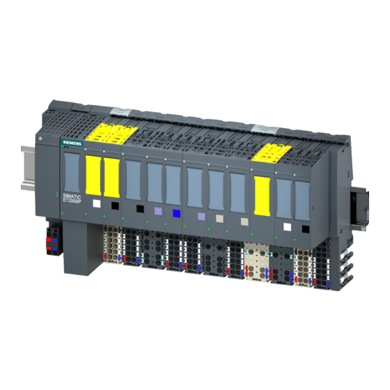
Product overview Properties Article number 6ES7155-6AR00-0AN0 (IM 155-6 PN BA interface module and server module) View of the module Figure 2-1 View of the IM 155-6 PN BA interface module and the server module Properties The module has the following properties: ●... - Page 9 ● Reference identification label A detailed list of the available accessories can be found in the system manual ET 200SP distributed I/O system (http://support.automation.siemens.com/WW/view/en/58649293). Server module The server module (V1.1.1 and higher) is included in the scope of delivery of the interface module and also available separately as an accessory.
-
Page 10: Functions
You can find more information on this topic in the STEP 7 online help and ● As of STEP 7 V12, in the function manual PROFINET with STEP 7 V13 (http://support.automation.siemens.com/WW/view/de/49948856/0/en) ● As of STEP 7 V5.5, in the system manual PROFINET System Description (http://support.automation.siemens.com/WW/view/en/19292127). - Page 11 IO devices that have already been used in another configuration should be reset to their factory settings before reuse (see system manual ET 200SP distributed I/O system (http://support.automation.siemens.com/WW/view/en/58649293)). You can find more information on this topic in the STEP 7 online help and ●...
-
Page 12: Configuration Control (Option Handling)
Reference You can find more information on configuration control ● in the ET 200SP distributed I/O system (http://support.automation.siemens.com/WW/view/en/58649293) system manual ● on the Internet under the following link Application collection (http://support.automation.siemens.com/WW/view/en/29430270) ● in the STEP 7 online help. -
Page 13: Wiring
Wiring Terminal assignment 24 V DC supply voltage The following table shows the signal names and the descriptions of the terminal assignment for a 24 V DC supply voltage. Table 3- 1 Terminal assignment 24 V DC supply voltage View Signal name Description Connector... - Page 14 Receive data - Ground Ground Reference You can find more information on accessories and how to connect the interface module in the system manual ET 200SP distributed I/O system (http://support.automation.siemens.com/WW/view/en/58649293). IM 155-6 PN BA interface module (6ES7155-6AR00-0AN0) Manual, 03/2015, A5E34934425-AA...
-
Page 15: Block Diagram
Wiring 3.2 Block diagram Block diagram The following figure shows the block diagram of the interface module IM 155-6 PN BA. ① Switch 24 V DC supply voltage ② ET 200SP backplane bus interface and electronics Ground ③ Backplane bus LK 1,2 LED Link TX/RX ④... -
Page 16: Parameters/Address Space
I/O modules. Reference You can find more information on the control data record in the ET 200SP distributed I/O system (http://support.automation.siemens.com/WW/view/en/58649293) system manual and in the STEP 7 online help. IM 155-6 PN BA interface module (6ES7155-6AR00-0AN0) Manual, 03/2015, A5E34934425-AA... -
Page 17: Substitute Value Behavior
The "Status of supply voltage L+ of the I/O modules" is configured in the IM 155-6 PN BA on the server module. The input data can then be read out on the server module. You will find the relevant description in the Server module (http://support.automation.siemens.com/WW/view/en/63257531) manual. IM 155-6 PN BA interface module (6ES7155-6AR00-0AN0) Manual, 03/2015, A5E34934425-AA... -
Page 18: Interrupts, Error Messages, Diagnostics And System Alarms
Interrupts, error messages, diagnostics and system alarms Status and error displays Introduction Diagnostics by means of LEDs is an initial tool for error localization. In order to localize errors still further, you usually evaluate the display of the module status in STEP 7 or the diagnostics buffer of the CPU. - Page 19 Hardware or firmware defective (the Run a firmware update. If the error LEDs LK1 and LK2 of the PROFINET persists, contact Siemens Industry interface do not flash). Online Support. Replace the interface module. * PWR LED on (on the interface module): Check the backplane bus for a short circuit.
- Page 20 Interrupts, error messages, diagnostics and system alarms 5.1 Status and error displays PWR LED on the interface module Table 5- 2 PWR status display on the interface module PWR LED Meaning Solution No or insufficient supply voltage Check the supply voltage. Supply voltage present LK1/LK2 LED on the interface module Table 5- 3...
- Page 21 Interrupts, error messages, diagnostics and system alarms 5.1 Status and error displays Operating principle You determine the information for cause of the error with the LED error display. After notification by the flash signal, the error type is displayed followed by the error location/error code.
- Page 22 Interrupts, error messages, diagnostics and system alarms 5.1 Status and error displays Error display The following table shows the possible causes of error that can occur. Table 5- 5 Error display Error type Error location Cause of error Remedy (MAINT) (ERROR/MAINT) 02 to 12* The number of pulled I/O modules is...
-
Page 23: Interrupts
CPU S7-1500, the CPU web server and the HMI device. For more information on system diagnostics, refer to the System Diagnostics function manual. (http://support.automation.siemens.com/WW/view/en/59192926). 5.2.1 Triggering a diagnostics interrupt Triggering a diagnostics interrupt For an incoming or outgoing event (e.g. -
Page 24: Triggering A Hardware Interrupt
Interrupts, error messages, diagnostics and system alarms 5.2 Interrupts 5.2.2 Triggering a hardware interrupt Triggering a hardware interrupt If there is a hardware interrupt, the CPU interrupts user program execution and processes the hardware interrupt block OB 40. The result that triggered the interrupt is added to the start information of the hardware interrupt block. -
Page 25: Alarms
Additional information on the data records for PROFINET IO The structure of the diagnostic data records and programming examples are available in the programming manual From PROFIBUS DP to PROFINET IO (http://support.automation.siemens.com/WW/view/en/19289930) and in Application example (http://support.automation.siemens.com/WW/view/en/24000238). Causes of error and corrective measures... -
Page 26: Channel Diagnostics
Interrupts, error messages, diagnostics and system alarms 5.3 Alarms See also Channel diagnostics (Page 26) PROFINET with STEP 7 V11 (http://support.automation.siemens.com/WW/view/en/49948856) 5.3.1 Channel diagnostics Function Channel-related diagnostics provides information about channel faults in modules. Channel faults are mapped as channel diagnostics data in IO diagnostics data records. -
Page 27: Invalid Configuration States Of The Et 200Sp On Profinet Io
Interrupts, error messages, diagnostics and system alarms 5.3 Alarms 5.3.2 Invalid configuration states of the ET 200SP on PROFINET IO Invalid configuration states The following invalid configuration states of the ET 200SP distributed I/O system lead to the failure of the IO device or prevent the exchange of user data with the I/O modules. ●... -
Page 28: Stop Of The Io Controller And Recovery Of The Io Device
Interrupts, error messages, diagnostics and system alarms 5.3 Alarms 5.3.4 STOP of the IO controller and recovery of the IO device STOP of the SIMATIC IO controller Diagnostics frames received from the IO device while the IO controller is in STOP do not initiate a call of any corresponding OBs when the IO controller goes into RUN. -
Page 29: Compatibility
Compatibility Status of the supply voltage Load voltage diagnostics are only valid if the station started up with a valid and complete configuration. ● For modules in the following table without a parameter assignment, the status of the supply voltage is always signaled as "1" regardless of the actual status of the supply voltage. -
Page 30: Technical Specifications
Technical specifications Technical specifications of the IM 155-6 PN BA Table 7- 1 Technical specifications of the IM 155-6 PN BA 6ES7155-6AR00-0AN0 Product type designation IM 155-6 PN BA with 2xRJ45 ports and server module General information Hardware version FS01 Firmware version V3.2 Product function... - Page 31 Technical specifications 6ES7155-6AR00-0AN0 Hardware configuration Rack Modules per rack, max. Interfaces Number of PROFINET interfaces 1st interface Interface hardware Number of ports • Integrated switch • Yes; 2 integrated RJ45 ports RJ45 (Ethernet) • BusAdapter (PROFINET) • Protocols PROFINET IO device •...
- Page 32 Technical specifications 6ES7155-6AR00-0AN0 Interrupts/diagnostics/status information Status display Interrupts Interrupts Diagnostics indicator LED RUN LED Yes; green LED ERROR LED Yes; red LED MAINT LED Yes; yellow LED Monitoring of the supply voltage (PWR LED) Yes; green PWR LED Connection display LINK TX/RX Yes;...
-
Page 33: Dimension Drawing
Dimension drawing This appendix contains a dimension drawing of the module mounted on a mounting rail. Always observe the specified dimensions for installation in cabinets, control rooms, etc. Figure A-1 Dimension drawing of the IM 155-6 PN BA interface module (front and side view) IM 155-6 PN BA interface module (6ES7155-6AR00-0AN0) Manual, 03/2015, A5E34934425-AA...