Table of Contents
Advertisement
Quick Links
HP ProLiant DL80 Gen9 Server
Maintenance and Service Guide
Abstract
This guide describes identification and maintenance procedures, diagnostic tools, specifications and requirements for hardware components and
software. This guide is for an experienced service technician. HP assumes that you are qualified in the servicing of computer equipment, trained in
recognizing hazards in products, and are familiar with weight and stability precautions.
Part Number: 785385-002
March 2015
Edition: 2
Advertisement
Table of Contents

Related Manuals for HP ProLiant DL80 Gen9


Summary of Contents for HP ProLiant DL80 Gen9
- Page 1 This guide describes identification and maintenance procedures, diagnostic tools, specifications and requirements for hardware components and software. This guide is for an experienced service technician. HP assumes that you are qualified in the servicing of computer equipment, trained in recognizing hazards in products, and are familiar with weight and stability precautions.
- Page 2 © Copyright 2014, 2015 Hewlett-Packard Development Company, L.P. The information contained herein is subject to change without notice. The only warranties for HP products and services are set forth in the express warranty statements accompanying such products and services. Nothing herein should be construed as constituting an additional warranty. HP shall not be liable for technical or editorial errors or omissions contained herein.
-
Page 3: Table Of Contents
4-bay LFF non-hot-plug drive backplane ...................... 36 4-bay LFF hot-plug drive backplane ......................37 HP Smart Storage Battery ......................... 38 HP Smart Storage Battery retainer ......................39 FBWC module ............................40 M.2 SSD enablement kit ........................... 41 Fan and fan blank ........................... 44 Fan population guidelines ....................... - Page 4 Diagnostic tools .......................... 83 Product QuickSpecs ..........................83 HP iLO ..............................83 Active Health System........................84 HP ProLiant Pre-boot Health Summary ....................84 Integrated Management Log ......................85 HP UEFI System Utilities ..........................85 Using HP UEFI System Utilities ......................85 Embedded Diagnostics option ......................
- Page 5 HP Smart Storage Battery cabling ......................112 Fan cabling ............................112 GPU power cabling ..........................113 Power supply cabling..........................113 HP 550-W Power Supply cabling (non-hot-plug) ................113 HP Redundant Power Supply cabling (hot-plug) ................114 Front panel cabling ..........................114 Specifications ........................... 116 Environmental specifications ........................
-
Page 6: Customer Self Repair
HP specifies in the materials shipped with a replacement CSR part whether a defective part must be returned to HP. In cases where it is required to return the defective part to HP, you must ship the defective part back to HP within a defined period of time, normally five (5) business days. The defective part must be returned with the associated documentation in the provided shipping material. - Page 7 HP sono realizzati con numerosi componenti che possono essere riparati direttamente dal cliente (CSR, Customer Self Repair). Se in fase di diagnostica HP (o un centro di servizi o di assistenza HP) identifica il guasto come riparabile mediante un ricambio CSR, HP lo spedirà direttamente al cliente per la sostituzione.
- Page 8 La mancata restituzione del componente può comportare la fatturazione del ricambio da parte di HP. Nel caso di riparazione da parte del cliente, HP sostiene tutte le spese di spedizione e resa e sceglie il corriere/vettore da utilizzare.
- Page 9 Si, durante la fase de diagnóstico, HP (o los proveedores o socios de servicio de HP) identifica que una reparación puede llevarse a cabo mediante el uso de un componente CSR, HP le enviará dicho componente directamente para que realice su sustitución. Los componentes CSR se clasifican en dos categorías:...
- Page 10 HP podrá cobrarle por el de sustitución. En el caso de todas sustituciones que lleve a cabo el cliente, HP se hará cargo de todos los gastos de envío y devolución de componentes y escogerá la empresa de transporte que se utilice para dicho servicio.
- Page 11 Opcional – Peças cujo reparo feito pelo cliente é opcional. Essas peças também são projetadas para o reparo feito pelo cliente. No entanto, se desejar que a HP as substitua, pode haver ou não a cobrança de taxa adicional, dependendo do tipo de serviço de garantia destinado ao produto.
- Page 12 No caso desse serviço, a substituição de peças CSR é obrigatória. Se desejar que a HP substitua essas peças, serão cobradas as despesas de transporte e mão-de-obra do serviço. Customer self repair 12...
- Page 13 Customer self repair 13...
- Page 14 Customer self repair 14...
- Page 15 Customer self repair 15...
-
Page 16: Illustrated Parts Catalog
Optional—Parts for which customer self repair is optional. These parts are also designed for customer self repair. If, however, you require that HP replace them for you, there may or may not be additional charges, depending on the type of warranty service designated for your product. - Page 17 Optional: Opcional—Peças cujo reparo feito pelo cliente é opcional. Essas peças também são projetadas para o reparo feito pelo cliente. No entanto, se desejar que a HP as substitua, pode haver ou não a cobrança de taxa adicional, dependendo do tipo de serviço de garantia destinado ao produto.
- Page 18 No: Nenhuma—Algumas peças da HP não são projetadas para o reparo feito pelo cliente. A fim de cumprir a garantia do cliente, a HP exige que um técnico autorizado substitua a peça. Essas peças estão identificadas com a marca “No”...
-
Page 19: System Components
System components HP continually improves and changes product parts. For complete and current supported parts information, see the HP PartSurfer website (http://partsurfer.hp.com). Item Description Spare part Customer self number repair (on page 6) GPU riser board 790525-001 Optional Two-slot PCIe riser board... - Page 20 Optional HP 900-W Gold AC Power Input Module 754376-001 Mandatory System cables — — a) 4-bay LFF hot-plug Mini-SAS cable for HP Smart 790544-001 Mandatory Host Bus Adapter* b) 4-bay LFF hot-plug Mini-SAS Y-cable for HP Smart 790543-001 Mandatory Array P-series Controller*...
- Page 21 Optional—Parts for which customer self repair is optional. These parts are also designed for customer self repair. If, however, you require that HP replace them for you, there may or may not be additional charges, depending on the type of warranty service designated for your product.
- Page 22 Optional: Opcional—Peças cujo reparo feito pelo cliente é opcional. Essas peças também são projetadas para o reparo feito pelo cliente. No entanto, se desejar que a HP as substitua, pode haver ou não a cobrança de taxa adicional, dependendo do tipo de serviço de garantia destinado ao produto.
-
Page 23: Removal And Replacement Procedures
T-10/T-15 Torx screwdriver • Flathead screwdriver (for replacing the system battery) • HP Insight Diagnostics (on page 87) Safety considerations Before performing service procedures, review all the safety information. Preventing electrostatic discharge To prevent damaging the system, be aware of the precautions you need to follow when setting up the system or handling parts. -
Page 24: Server Warnings And Cautions
Get help to lift and stabilize the product during installation or removal, especially when the • product is not fastened to the rails. HP recommends that a minimum of two people are required for all rack server installations. A third person may be required to help align the server if the server is installed higher than chest level. -
Page 25: Rack Warnings
Extend the server from the rack (on page 27). If you are performing service procedures in an HP, Compaq branded, Telco, or third-party rack cabinet, you can use the locking feature of the rack rails to support the server and gain access to internal components. -
Page 26: Remove The Security Bezel (Optional)
If the rack environment, cabling configuration, or the server location in the rack creates awkward conditions, remove the server from the rack. • Remove the access panel ("Access panel" on page 34). • Remove the PCI riser cages (on page 30). •... -
Page 27: Extend The Server From The Rack
Before proceeding, verify the server is in standby mode by observing that the system power LED is amber. Extend the server from the rack WARNING: To reduce the risk of personal injury or equipment damage, be sure that the rack is adequately stabilized before extending a component from the rack. - Page 28 Slide the server out of the rack. After performing the installation or maintenance procedure, slide the server back into the rack, and then press the server firmly into the rack to secure it in place. Do one of the following: In a server that uses thumbscrew rack ears, tighten the captive thumbscrews.
-
Page 29: Access The Product Rear Panel
Access the product rear panel Opening the cable management arm To access the server rear panel: Release the cable management arm. Open the cable management arm. The cable management arm can be right-mounted or left-mounted. Remove the server from the rack Removal and replacement procedures 29... -
Page 30: Remove The Pci Riser Cages
Get help to lift and stabilize the product during installation or removal, especially when the product is not fastened to the rails. HP recommends that a minimum of two people are required for all rack server installations. A third person may be required to help align the server if the server is installed higher than chest level. -
Page 31: Non-Hot-Plug Drive Carrier
Disconnect all cables connected to existing expansion boards. Loosen the captive thumbscrew on the front end of the PCI riser cage, and then remove the screws from its rear end. Grasp the PCI riser cage at the touch points and lift it out of the chassis. If you are removing the FlexibleLOM riser cage from the secondary PCIe riser location, do the following: Disconnect all cables connected to existing expansion boards. -
Page 32: Non-Hot-Plug Drive
CAUTION: To prevent improper cooling and thermal damage, do not operate the server unless all bays are populated with either a component or a blank. To remove the component: Power down the server (on page 26). Remove all power: Disconnect each power cord from the power source. Disconnect each power cord from the server. -
Page 33: Hot-Plug Drive Blank
Remove the non-hot-plug drive. Remove the drive from the carrier. To replace the component, reverse the removal procedure. Hot-plug drive blank CAUTION: To prevent improper cooling and thermal damage, do not operate the server unless all bays are populated with either a component or a blank. To remove the component: If installed, remove the security bezel ("Remove the security bezel... -
Page 34: Hot-Plug Drive
If installed, remove the security bezel ("Remove the security bezel (optional)" on page 26). Determine the status of the drive from the drive LED definitions ("HP SmartDrive LED definitions" on page 101). Remove the hot-plug drive. To replace the component, reverse the removal procedure. -
Page 35: Air Baffle
Open the locking latch. The access panel slides back, releasing it from the chassis. Lift and remove the access panel. To replace the component, reverse the removal procedure. Air baffle CAUTION: For proper cooling, do not operate the server without the access panel, baffles, expansion slot covers, or blanks installed. -
Page 36: 4-Bay Lff Non-Hot-Plug Drive Backplane
Remove the air baffle. To replace the component, reverse the removal procedure. 4-bay LFF non-hot-plug drive backplane WARNING: To reduce the risk of personal injury from hot surfaces, allow the drives and the internal system components to cool before touching them. CAUTION: To prevent damage to electrical components, take the appropriate anti-static precautions before beginning any installation, removal, or replacement procedure. -
Page 37: 4-Bay Lff Hot-Plug Drive Backplane
Remove the drive backplane. To replace the component, reverse the removal procedure. 4-bay LFF hot-plug drive backplane WARNING: To reduce the risk of personal injury from hot surfaces, allow the drives and the internal system components to cool before touching them. CAUTION: To prevent damage to electrical components, take the appropriate anti-static precautions before beginning any installation, removal, or replacement procedure. -
Page 38: Hp Smart Storage Battery
Extend the server from the rack (on page 27). Remove the server from the rack (on page 29). Remove the access panel ("Access panel" on page 34). Remove the air baffle ("Air baffle" on page 35). Disconnect the HP Smart Storage Battery cable. Removal and replacement procedures 38... -
Page 39: Hp Smart Storage Battery Retainer
Push the HP Smart Storage Battery retainer backward to release the battery, and then remove the battery from the chassis. To replace the component, reverse the removal procedure. HP Smart Storage Battery retainer WARNING: To reduce the risk of personal injury from hot surfaces, allow the drives and the internal system components to cool before touching them. -
Page 40: Fbwc Module
Using your hand or a small plier, pull the retainer pin up to disengage its bottom part from the chassis, and then slide the retainer forward to remove it from the chassis. To replace the component, reverse the removal procedure. FBWC module WARNING: To reduce the risk of personal injury from hot surfaces, allow the drives and the... -
Page 41: M.2 Ssd Enablement Kit
Remove the cache module. To replace the component, reverse the removal procedure. M.2 SSD enablement kit For more information about product features, specifications, options, configurations, and compatibility, see the product QuickSpecs on the HP website (http://www.hp.com/go/qs). Removal and replacement procedures 41... - Page 42 To remove the component: Power down the server (on page 26). Remove all power: Disconnect each power cord from the power source. Disconnect each power cord from the server. Do one of the following: Extend the server from the rack (on page 27). Remove the server from the rack (on page 29).
- Page 43 Remove the M.2 SSD enablement board. M.2 SSD enablement board removal from the system board M.2 SSD enablement board removal from the FlexibleLOM riser cage To replace the component, reverse the removal procedure. Removal and replacement procedures 43...
-
Page 44: Fan And Fan Blank
Fan and fan blank Fan population guidelines To provide sufficient airflow to the system if a fan fails, the server supports redundant fans. Configuration Fan bay 1 Fan bay 2 Fan bay 3 Fan bay 4 Fan bay 5 Fan bay 6 One processor, non-redundant Blank Blank Blank... -
Page 45: Hot-Swap Fan
CAUTION: To prevent damage to electrical components, take the appropriate anti-static precautions before beginning any installation, removal, or replacement procedure. Improper grounding can cause electrostatic discharge. CAUTION: To prevent improper cooling and thermal damage, do not operate the server unless all bays are populated with either a component or a blank. -
Page 46: Dimm
CAUTION: To prevent improper cooling and thermal damage, do not operate the server unless all bays are populated with either a component or a blank. To remove the component: Power down the server (on page 26). Remove all power: Disconnect each power cord from the power source. Disconnect each power cord from the server. -
Page 47: Processor Blank
To remove the component: Power down the server (on page 26). Remove all power: Disconnect each power cord from the power source. Disconnect each power cord from the server. Do one of the following: Extend the server from the rack (on page 27). Remove the server from the rack (on page 29). -
Page 48: Heatsink
Disconnect each power cord from the server. Do one of the following: Extend the server from the rack (on page 27). Remove the server from the rack (on page 29). Remove the access panel ("Access panel" on page 34). Remove the air baffle ("Air baffle"... - Page 49 Remove the heatsink: Loosen one pair of diagonally opposite screws halfway, and then loosen the other pair of screws. Completely loosen all screws in the same sequence. Remove the heatsink from the processor backplate. To replace the component: Clean the old thermal grease from the processor with the alcohol swab. Allow the alcohol to evaporate before continuing.
-
Page 50: Processor
Finish the installation by completely tightening the screws in the same sequence. Install the air baffle. Install the access panel. Do one of the following: Slide the server into the rack. Install the server into the rack. Connect each power cord to the server. Connect each power cord to the power source. - Page 51 IMPORTANT: If installing a processor with a faster speed, update the system ROM before installing the processor. IMPORTANT: Processor socket 1 must be populated at all times or the server does not function. To remove the component: Power down the server (on page 26). Remove all power: Disconnect each power cord from the power source.
- Page 52 Remove the processor from the processor retaining bracket. To replace the component: Install the processor. Verify that the processor is fully seated in the processor retaining bracket by visually inspecting the processor installation guides on either side of the processor. THE PINS ON THE SYSTEM BOARD ARE VERY FRAGILE AND EASILY DAMAGED.
- Page 53 CAUTION: THE PINS ON THE SYSTEM BOARD ARE VERY FRAGILE AND EASILY DAMAGED. To avoid damage to the system board, do not touch the processor or the processor socket contacts. CAUTION: Do not press down on the processor. Pressing down on the processor may cause damage to the processor socket and the system board.
-
Page 54: Expansion Board
Install the heatsink: Position the heatsink on the processor backplate. Tighten one pair of diagonally opposite screws halfway, and then tighten the other pair of screws. Finish the installation by completely tightening the screws in the same sequence. Install the air baffle. Install the access panel. - Page 55 Remove all power: Disconnect each power cord from the power source. Disconnect each power cord from the server. Do one of the following: Extend the server from the rack (on page 27). Remove the server from the rack (on page 29). Remove the access panel ("Access panel"...
-
Page 56: Primary Pci Riser Cage Blank
Low-profile expansion board removal from the FlexibleLOM riser cage FlexibleLOM adapter removal from the FlexibleLOM riser cage If you are removing a storage controller board with a cache module installed, remove the cache module ("FBWC module" on page 40). To replace the component, reverse the removal procedure. Primary PCI riser cage blank WARNING: To reduce the risk of personal injury from hot surfaces, allow the drives and the... - Page 57 To remove the component: Power down the server (on page 26). Remove all power: Disconnect each power cord from the power source. Disconnect each power cord from the server. Do one of the following: Extend the server from the rack (on page 27). Remove the server from the rack (on page 29).
-
Page 58: Onboard Low-Profile Pci Expansion Slot Cover
Onboard low-profile PCI expansion slot cover CAUTION: To prevent damage to electrical components, take the appropriate anti-static precautions before beginning any installation, removal, or replacement procedure. Improper grounding can cause electrostatic discharge. CAUTION: To prevent improper cooling and thermal damage, do not operate the server unless all bays are populated with either a component or a blank. -
Page 59: Flexiblelom Riser Cage
CAUTION: To prevent damage to electrical components, take the appropriate anti-static precautions before beginning any installation, removal, or replacement procedure. Improper grounding can cause electrostatic discharge. To remove the component: Power down the server (on page 26). Remove all power: Disconnect each power cord from the power source. -
Page 60: Gpu Riser Board
GPU riser board WARNING: To reduce the risk of personal injury from hot surfaces, allow the drives and the internal system components to cool before touching them. CAUTION: To prevent damage to electrical components, take the appropriate anti-static precautions before beginning any installation, removal, or replacement procedure. Improper grounding can cause electrostatic discharge. -
Page 61: Flexiblelom Riser Board
Remove all power: Disconnect each power cord from the power source. Disconnect each power cord from the server. Do one of the following: Extend the server from the rack (on page 27). Remove the server from the rack (on page 29). Remove the access panel ("Access panel"... -
Page 62: System Battery
Remove the FlexibleLOM riser board. To replace the component, reverse the removal procedure. System battery If the server no longer automatically displays the correct date and time, then replace the battery that provides power to the real-time clock. Under normal use, battery life is 5 to 10 years. WARNING: The computer contains an internal lithium manganese dioxide, a vanadium pentoxide, or an alkaline battery pack. -
Page 63: Front I/O Assembly
Replacing the system board battery resets the system ROM to its default configuration. After replacing the battery, use BIOS/Platform Configuration (RBSU) in the UEFI System Utilities ("HP UEFI System Utilities" on page 85) to reconfigure the system. To install the component: Insert the battery with the "+"... - Page 64 Remove all power: Disconnect each power cord from the power source. Disconnect each power cord from the server. Do one of the following: Extend the server from the rack (on page 27). Remove the server from the rack (on page 29). Remove the access panel ("Access panel"...
-
Page 65: Thumbscrew Rack Ears
Remove the front I/O assembly. To replace the component, reverse the removal procedure. Thumbscrew rack ears To remove the component: Power down the server (on page 26). Remove all power: Disconnect each power cord from the power source. Disconnect each power cord from the server. Remove the server from the rack (on page 29). -
Page 66: Quick-Release Latch Rack Ear Assembly
Right thumbscrew rack ear Left thumbscrew rack ear To replace the component, reverse the removal procedure. Quick-release latch rack ear assembly WARNING: To reduce the risk of personal injury from hot surfaces, allow the drives and the internal system components to cool before touching them. CAUTION: To prevent damage to electrical components, take the appropriate anti-static precautions before beginning any installation, removal, or replacement procedure. - Page 67 Remove all power: Disconnect each power cord from the power source. Disconnect each power cord from the server. Remove the server from the rack (on page 29). Place the server on a sturdy, level surface. If installed, remove the security bezel ("Remove the security bezel (optional)"...
- Page 68 Release the front I/O cabling from the side chassis metal clip. Remove the right quick-release latch rack ear assembly. Removal and replacement procedures 68...
-
Page 69: System Board
Remove the left quick-release latch rack ear. To replace the component, reverse the removal procedure. System board WARNING: To reduce the risk of personal injury from hot surfaces, allow the drives and the internal system components to cool before touching them. CAUTION: To prevent damage to electrical components, take the appropriate anti-static precautions before beginning any installation, removal, or replacement procedure. - Page 70 Remove all DIMMs ("DIMM" on page 46). Remove the heatsink: Loosen one pair of diagonally opposite screws halfway, and then loosen the other pair of screws. Completely loosen all screws in the same sequence. Remove the heatsink from the processor backplate. Open each of the processor locking levers in the order indicated, and then open the processor retaining bracket.
- Page 71 Remove the processor from the processor retaining bracket. Disconnect all cables connected to the system board. Remove the failed system board. Removal and replacement procedures 71...
- Page 72 To replace the system board: Install the system board. Open each of the processor locking levers in the order indicated, and then open the processor retaining bracket. Removal and replacement procedures 72...
- Page 73 Remove the clear processor socket cover. Retain the processor socket cover for future use. Install the processor. Verify that the processor is fully seated in the processor retaining bracket by visually inspecting the processor installation guides on either side of the processor. THE PINS ON THE SYSTEM BOARD ARE VERY FRAGILE AND EASILY DAMAGED.
- Page 74 CAUTION: Close and hold down the processor cover socket while closing the processor locking levers. The levers should close without resistance. Forcing the levers closed can damage the processor and socket, requiring system board replacement. Close the processor retaining bracket. When the processor is installed properly inside the processor retaining bracket, the processor retaining bracket clears the flange on the front of the socket.
- Page 75 Position the heatsink on the processor backplate. Tighten one pair of diagonally opposite screws halfway, and then tighten the other pair of screws. Finish the installation by completely tightening the screws in the same sequence. Install all components removed from the failed system board. Connect all cables disconnected from the failed system board.
-
Page 76: Hp 550-W Power Supply
Enter the product ID and press the Enter key. Press the F10 key to confirm exiting System Utilities. The server automatically reboots. HP 550-W Power Supply WARNING: To reduce the risk of personal injury from hot surfaces, allow the drives and the internal system components to cool before touching them. - Page 77 If the primary PCI riser cage is installed, do the following: Remove the primary PCI riser cage ("Remove the PCI riser cages" on page 30). Remove the PCI air baffle. Disconnect the non-hot-plug power supply cables. Release the non-hot-plug power supply cables from the cable clip. Removal and replacement procedures 77...
-
Page 78: Hot-Plug Power Input Module
Remove the non-hot-plug power supply. To replace the component, reverse the removal procedure. Hot-plug power input module To remove the component: If the server is using a single hot-plug power input module only, power down the server (on page 26). Access the product rear panel (on page 29). -
Page 79: Rps Backplane
Remove the power input module. To replace the component, reverse the removal procedure. RPS backplane WARNING: To reduce the risk of personal injury from hot surfaces, allow the drives and the internal system components to cool before touching them. CAUTION: To prevent damage to electrical components, take the appropriate anti-static precautions before beginning any installation, removal, or replacement procedure. - Page 80 Remove the PCI air baffle. Disconnect the RPS backplane cables. Release the RPS backplane cables from the cable clips. Removal and replacement procedures 80...
-
Page 81: Hp Trusted Platform Module
If you suspect a TPM board failure, leave the TPM installed and remove the system board ("System board" on page 69). Contact an HP authorized service provider for a replacement system board and TPM board. Removal and replacement procedures 81... -
Page 82: Troubleshooting
• Simplified Chinese (http://www.hp.com/support/Gen9_TSG_zh_cn) The HP ProLiant Gen9 Troubleshooting Guide, Volume II: Error Messages provides a list of error messages and information to assist with interpreting and resolving error messages on ProLiant servers and server blades. To view the guide, select a language: •... -
Page 83: Diagnostic Tools
QuickSpecs on the HP website (http://www.hp.com/go/qs). HP iLO The iLO 4 subsystem is a standard component of HP ProLiant servers that simplifies initial server setup, server health monitoring, power and thermal optimization, and remote server administration. The iLO 4 subsystem includes an intelligent microprocessor, secure memory, and a dedicated network interface. -
Page 84: Active Health System
HP Active Health System does not parse or change operating system data from third-party error event log activities, such as content created or passed through by the operating system. The data that is collected is managed according to the HP Data Privacy policy. For more information see the HP website (http://www.hp.com/go/privacy). -
Page 85: Integrated Management Log
• From within HP Insight Diagnostics (on page 87) HP UEFI System Utilities The HP UEFI System Utilities is embedded in the system ROM. The UEFI System Utilities enable you to perform a wide range of configuration activities, including: •... -
Page 86: Embedded Diagnostics Option
Embedded Diagnostics option The system BIOS in all HP ProLiant Gen9 servers includes an Embedded Diagnostics option in the ROM. The Embedded Diagnostics option can run comprehensive diagnostics of the server hardware, including processors, memory, drives, and other server components. -
Page 87: Hp Insight Diagnostics
USB support HP servers support both USB 2.0 ports and USB 3.0 ports. Both types of ports support installing all types of USB devices (USB 1.0, USB 2.0, and USB 3.0), but may run at lower speeds in specific situations: •... -
Page 88: External Usb Functionality
Gen8 servers, HP SSA replaces ACU with an enhanced GUI and additional configuration features. HP SSA exists in three interface formats: the HP SSA GUI, the HP SSA CLI, and HP SSA Scripting. Although all formats provide support for configuration tasks, some of the advanced tasks are available in only one format. -
Page 89: Automatic Server Recovery
ASR is a feature that causes the system to restart when a catastrophic operating system error occurs, such as a blue screen, ABEND (does not apply to HP ProLiant DL980 Servers), or panic. A system fail-safe timer, the ASR timer, starts when the System Management driver, also known as the Health Driver, is loaded. When the operating system is functioning properly, the system periodically resets the timer. -
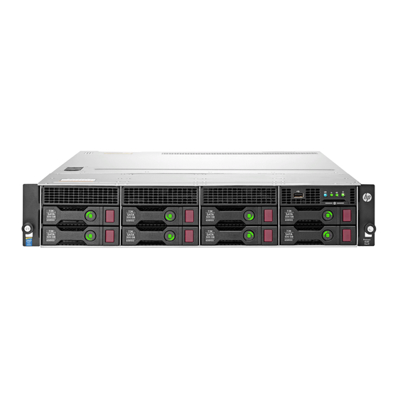
Page 90: Component Identification
Component identification Front panel components • 4-bay LFF non-hot-plug drive model Item Description USB 2.0 connector Serial label pull tab ("Serial label pull tab information" on page 91) LFF non-hot-plug drives • 8-bay LFF non-hot-plug drive model Item Description USB 2.0 connector Serial label pull tab ("Serial label pull tab information"... -
Page 91: Serial Label Pull Tab Information
Reverse side—Default iLO account information and the server QR code label Use your mobile device to scan the QR code label to display the server mobile product page (http://www.hp.com/qref/dl80gen9). This page contains links to server setup information, spare part numbers, QuickSpecs, troubleshooting resources, and other useful product links. -
Page 92: Front Panel Leds And Buttons
Front panel LEDs and buttons • Front panel LEDs and buttons in a 4-bay LFF chassis with thumbscrew rack ears • Front panel LEDs and buttons in an 8-bay LFF chassis with thumbscrew rack ears • Front panel LEDs and buttons in a 12-bay LFF chassis with quick-release lever rack ears Component identification 92... -
Page 93: Front Panel Led Power Fault Codes
3 flashes Memory 4 flashes Riser board PCIe slots 5 flashes FlexibleLOM 6 flashes Removable HP Flexible Smart Array controller/Smart SAS HBA controller 7 flashes System board PCIe slots 8 flashes Power backplane or storage backplane 9 flashes Power supply For more information, see "Front panel LEDs and buttons (on page 92)."... -
Page 94: Rear Panel Components
Rear panel components Item Description Slot 7 PCIe3 x16 (16, 8, 4, 1) low-profile, standup Slot 6 PCIe3 x8 (8, 4, 1) low-profile, standup Slot 4 PCIe3 x8 (8, 4, 1) low-profile, riser (optional) Slot 5 PCIe3 x8 (8, 4, 1) FlexibleLOM riser (optional) Slot 4 PCIe3 x16 (16, 8, 4, 1) low-profile, standup Slot 3 PCIe3 x8 (8, 4, 1) low-profile, standup Slot 1 PCIe3 x16 (16, 8, 4, 1) low-profile, standup... -
Page 95: Rear Panel Leds
Rear panel LEDs Item Description Status UID LED Solid blue = Activated Flashing blue: • 1 Hz/cycle per sec = Remote management or firmware upgrade in progress • 4 Hz/cycle per sec = iLO manual reboot sequence initiated • 8 Hz/cycle per sec = iLO manual reboot sequence in progress Off = Deactivated NIC link LED... -
Page 96: Pcie Riser Board Slot Definitions
PCIe riser board slot definitions • GPU riser cage assembly: Install in the primary PCIe riser board connector. Item Riser slot number Form factor Slot description Full-height, full-length PCIe3 x16 (16, 8, 4, 1) • Two-slot PCI riser cage assembly: Install in the primary PCIe riser board connector. Item Riser slot number Form factor... - Page 97 • FlexibleLOM riser cage assembly: Install in the secondary PCIe riser board connector. Item Riser slot number Form factor Slot description Low-profile PCIe3 x8 (8, 4, 1) FlexibleLOM PCIe3 x8 Component identification 97...
-
Page 98: System Board Components
System board components Item Description PCIe3 x16 (16, 8, 4, 1) slot 1 for low-profile, standup expansion board or riser cage options (GPU riser cage or two-slot PCI riser cage) TPM connector System battery SATA connector 4 (for M.2 SSD 1) Storage backup power connector for a controller board installed in the two-slot PCI riser cage or in the onboard PCIe3 x8 slot 3... -
Page 99: Dimm Slot Locations
Processor 1 DIMM slots Fan connector 3 Fan connector 2 Fan connector 1 Processor 1 HP Smart Storage Battery connector 6-pin drive power connector Internal USB 3.0 connector 24-pin power supply connector 16-pin RPS connector SATA connector 5 (for M.2 SSD 2) -
Page 100: Nmi Functionality
IMPORTANT: Before using the S7 switch to change to Legacy BIOS Boot Mode, be sure the HP Dynamic Smart Array B140i Controller is disabled. Do not use the B140i controller when the server is in Legacy BIOS Boot Mode. -
Page 101: Hp Smartdrive Led Definitions
12-bay LFF hot-plug drive numbering HP SmartDrive LED definitions HP SmartDrives are the latest HP drive technology, and they are supported beginning with ProLiant Gen8 servers and server blades. The HP SmartDrive is not supported on earlier generation servers and server blades. - Page 102 The blue Locate LED is behind the release lever and is visible when illuminated. IMPORTANT: The HP Dynamic Smart Array B140i Controller is only available in UEFI Boot Mode. It cannot be enabled in Legacy BIOS Boot Mode. If the B140i controller is disabled, drives connected to the system board Mini-SAS connectors operate in AHCI or Legacy mode.
-
Page 103: Fan Locations
Fan locations Component identification 103... -
Page 104: Cabling
For information on cabling peripheral components, refer to the white paper on high-density deployment at the HP website (http://www.hp.com/products/servers/platforms). CAUTION: When routing cables, always be sure that the cables are not in a position where they can be pinched or crimped. -
Page 105: 4-Bay Lff Hot-Plug Sata Drive Cabling
4-bay LFF hot-plug SATA drive cabling Item Description Drive power cable Mini-SAS cable 4-bay LFF hot-plug SAS/SATA drive cabling • Drives connected to an HBA option Item Description Drive power cable Mini-SAS cable Cabling 105... -
Page 106: 8-Bay Lff Non-Hot-Plug Sata Drive Cabling
• Drives connected to an HP Smart Array Controller option Item Description Drive power cable Mini-SAS cable 8-bay LFF non-hot-plug SATA drive cabling Item Description Drive power cable SATA cable 1 SATA cable 2 Cabling 106... -
Page 107: 8-Bay Lff Hot-Plug Sata Drive Cabling
8-bay LFF hot-plug SATA drive cabling Item Description Drive power cable Mini-SAS cable 1 Mini-SAS cable 2 8-bay LFF hot-plug SAS/SATA drive cabling • Drives connected to an HBA option Item Description Drive power cable Mini-SAS cable 1 Mini-SAS cable 2 Cabling 107... -
Page 108: 12-Bay Lff Hot-Plug Sas/Sata Drive Cabling
• Drives connected to an HP Smart Array Controller option Item Description Drive power cable Mini-SAS Y-cable 12-bay LFF hot-plug SAS/SATA drive cabling • Drives connected to an HBA option Item Description Box 1 drive power cable (BP1 connector of the GPU/BP1 power... - Page 109 Item Description Mini-SAS Y-cable for the box 3 drives • Drives connected to an HP Smart Array Controller option Item Description Box 1 drive power cable (BP1 connector of the GPU/BP1 power extension cable connected to the hot-plug power supply)
-
Page 110: M.2 Ssd Cabling
M.2 SSD cabling • M.2 SSD cabling from the onboard PCIe3 x16 slot 4 Item Description M.2 SSD 1 SATA cable M.2 SSD 2 SATA cable • M.2 SSD cabling from the FlexibleLOM riser cage Item Description M.2 SSD 1 SATA cable M.2 SSD 2 SATA cable Cabling 110... -
Page 111: Fbwc Module Backup Power Cabling
Depending on the controller option installed, the actual storage controller connectors might look different from what is shown in this section. • FBWC module backup power cabling from a standup, HP Smart Array P44x Controller installed in the onboard PCIe3 x8 slot 3 •... -
Page 112: Hp Smart Storage Battery Cabling
HP Smart Storage Battery cabling Fan cabling Item Description Fan 1 cable Fan 2 cable Fan 3 cable Fan 4 cable Fan 5 cable Fan 6 cable Cabling 112... -
Page 113: Gpu Power Cabling
GPU power cabling Item Description GPU power cable (GPU connector of the GPU/BP1 power extension cable) Hot-plug power supply GPU/BP1 power cable Power supply cabling HP 550-W Power Supply cabling (non-hot-plug) Item Description 24-pin power supply cable Cabling 113... -
Page 114: Hp Redundant Power Supply Cabling (Hot-Plug)
Item Description 16-pin RPS cable HP Redundant Power Supply cabling (hot-plug) Item Description GPU/BP1 power cable, requires the GPU/BP1 power extension cable 24-pin power supply cable 16-pin RPS cable Front panel cabling • Front panel cabling in a chassis with thumbscrew rack ears... - Page 115 Item Description USB 2.0 connector cable Ambient temperature sensor cable Front I/O cable • Front panel cabling in a chassis with quick-release latch rack ears Item Description Front I/O cable USB 2.0 connector cable Ambient temperature sensor cable Cabling 115...
-
Page 116: Specifications
40°C to 45°C (104°F to 113°F) at sea level with an altitude derating of 1.0°C per every 125 m (1.8°F per every 410 ft) above 900 m (2953 ft) to a maximum of 3048 m (10,000 ft). The approved hardware configurations for this system are listed on the HP website (http://www.hp.com/servers/ASHRAE). -
Page 117: Power Supply Specifications
This is supported when the two-bay HP RPS Backplane option (PN 745813-B21) is installed. These are Entry Level Power Supply products for HP ProLiant servers. For more information about the power supply features, specifications, and compatibility, see the HP website (http://www.hp.com/go/proliant/powersupply). -
Page 118: Acronyms And Abbreviations
ASHRAE American Society of Heating, Refrigerating and Air-Conditioning Engineers Automatic Server Recovery backplane Customer Self Repair file allocation table FBWC flash-backed write cache graphics processing unit host bus adapter HP SIM HP Systems Insight Manager Acronyms and abbreviations 118... - Page 119 HP SSA HP Smart Storage Administrator Integrated Lights-Out Integrated Management Log large form factor Lights-Out Management NAND Not AND nonmaskable interrupt NVRAM nonvolatile memory PCIe Peripheral Component Interconnect Express POST Power-On Self Test QR code quick response code RBSU ROM-Based Setup Utility...
- Page 120 SCSI SATA serial ATA Secure Digital Systems Insight Manager HP Service Pack for ProLiant solid-state drive serial, USB, video Trusted Platform Module UEFI Unified Extensible Firmware Interface unit identification universal serial bus Acronyms and abbreviations 120...
-
Page 121: Documentation Feedback
Documentation feedback HP is committed to providing documentation that meets your needs. To help us improve the documentation, send any errors, suggestions, or comments to Documentation Feedback (mailto:docsfeedback@hp.com). Include the document title and part number, version number, or the URL when submitting your feedback. -
Page 122: Index
Index drive carrier 31 drive LEDs 101 drive numbering 100 access panel 34 drives, determining status of 101 Active Health System 84 ACU (Array Configuration Utility) 88 ambient temperature 116 ambient temperature sensor, cabling 114 electrostatic discharge 23 Automatic Server Recovery (ASR) 89 embedded UEFI diagnostics 86 environmental specifications 116 error messages 82... - Page 123 HP Smart Storage Battery 38, 39 HP Smart Storage Battery cabling 112 HP SmartDrive LED definitions 101 operating system crash 89, 100 HP SSA (HP Smart Storage Administrator) 88 operating systems supported 87 HP Systems Insight Manager (SIM) 85, 87 HP technical support 6...
- Page 124 removing the I/O module 63 removing the security bezel 26 warnings 24, 25 required tools 23 weight 116 requirements, environmental 116 ROM legacy USB support 87 ROM-Based Setup Utility (RBSU) 85 RPS cabling 79 safety considerations 23 security bezel, removing 26 serial label pull tab 90, 91 serial number 86 serial number/iLO information pull tab 91...