Siemens SINAMICS S120 Manual
Modular motion control drive
Hide thumbs
Also See for SINAMICS S120:
- Function manual (1094 pages) ,
- Diagnostic manual (947 pages) ,
- Manual (848 pages)
Table of Contents
Advertisement
Advertisement
Table of Contents

Related Manuals for Siemens SINAMICS S120


Summary of Contents for Siemens SINAMICS S120
- Page 1 SINAMICS S120 Cabinet Modules Manual· 05/2010 SINAMICS...
- Page 3 ___________________ Cabinet Modules Preface ___________________ Safety information ___________________ System overview SINAMICS ___________________ Mechanical installation S120 ___________________ Cabinet Modules Electrical installation ___________________ Cabinet Modules Manual ___________________ Maintenance and servicing ___________________ Diagnostics ___________________ Options ___________________ Appendix A (GH5), 05/2010 A5E03263538A...
- Page 4 Note the following: WARNING Siemens products may only be used for the applications described in the catalog and in the relevant technical documentation. If products and components from other manufacturers are used, these must be recommended or approved by Siemens. Proper transport, storage, installation, assembly, commissioning, operation and maintenance are required to ensure that the products operate safely and without any problems.
-
Page 5: Preface
This documentation is aimed at machine manufacturers, plant engineers, commissioning engineers, and service personnel who use SINAMICS. Objective This manual describes the hardware components and design of the SINAMICS S120 Cabinet Modules. It provides information about installation, electrical connection, and cabinet design. - Page 6 Country-specific telephone numbers for technical support are provided at the following Internet address: http://www.automation.siemens.com/partners Internet addresses Up-to-date information about our products can be found on the Internet at the following address: http://www.siemens.com Information about SINAMICS S120 Cabinet Modules can be found under: http://www.siemens.com/sinamics-s120-cabinet-modules Cabinet Modules Manual, (GH5), 05/2010, A5E03263538A...
-
Page 7: Table Of Contents
Table of contents Preface ..............................5 Safety information............................ 15 Requirements..........................15 Electrostatic sensitive devices (ESD) ..................16 Safety information ........................17 Residual risks..........................19 System overview............................21 Overview ............................21 Field of application ........................23 Benefits ............................23 Line Modules..........................24 2.4.1 General information ........................24 2.4.2 Basic Line Modules........................24 2.4.3 Smart Line Modules ........................26 2.4.4... - Page 8 Table of contents 3.3.2.3 Shipping and handling indicators ....................47 3.3.2.4 Unpacking the cabinets....................... 49 3.3.2.5 Tools required ..........................49 3.3.3 Lifting the cabinet units off the transport pallet and installing them ..........50 3.3.4 Disassembling the crane transport assembly ................51 3.3.5 Connection to the foundation ......................
- Page 9 Table of contents 5.1.3.3 Version L44 for Smart Line Modules ..................129 5.1.4 Options............................130 5.1.5 Technical data..........................131 Basic Line Modules........................135 5.2.1 General information ........................135 5.2.2 Description ..........................135 5.2.3 Interfaces ...........................140 5.2.4 Options............................141 5.2.5 Technical data..........................142 Smart Line Modules ........................146 5.3.1 General information ........................146 5.3.2 Description ..........................146 5.3.3...
- Page 10 Table of contents 5.7.7.6 Technical data........................... 226 Auxiliary Power Supply Modules....................229 5.8.1 General information........................229 5.8.2 Description ..........................230 5.8.3 Fuse switch disconnector (-Q1) ....................234 5.8.4 Transformer (-T2) for generating the auxiliary voltage 230 V AC ..........234 5.8.5 Auxiliary power supply system ....................
- Page 11 Table of contents 6.4.13 Replacing the pre-charging resistors of the DC interface (option L37)........308 6.4.14 Replacing the backup battery for the cabinet operator panel ............309 Reforming the DC link capacitors ....................311 Diagnostics ............................313 Chapter content .........................313 LEDs on the CU320-2 DP Control Unit..................313 LEDs on the CBE20 Communication Board ................316 LEDs on the Control Interface Module in the Basic Line Module ..........318 LEDs on the Control Interface Module in the Smart Line Module ..........319...
- Page 12 Table of contents 8.10.4 Connection example ......................... 358 8.11 K51, VSM10 Voltage Sensing Module Cabinet-Mounted ............360 8.12 K76, auxiliary voltage generating unit in the Line Connection Module ........362 8.13 K82, terminal module for activating safety functions "Safe Torque Off" and "Safe Stop 1"..364 8.14 K87, Terminal Module TM54F....................
- Page 13 Table of contents 8.24.4.2 Parameterization with free function blocks ................409 8.24.4.3 Parameterization with DCC (Drive Control Chart) ..............413 8.25 L37, DC interface incl. pre-charging input circuit for the relevant DC link capacitance.....414 8.25.1 General information ........................414 8.25.2 DC interface incl. pre-charging for Booksize Cabinet Kits............414 8.25.2.1 Important safety precautions......................414 8.25.2.2 DC interface, principle of operation ...................416 8.25.2.3 Commissioning the DC interface when option K90 is being used ..........416...
- Page 14 Table of contents 8.42 M70, EMC shield bus ........................ 465 8.42.1 General information........................465 8.42.2 Connecting the cables to the EMC shield bus ................465 8.43 M80 to M87, DC busbar system ....................466 8.43.1 General information........................466 8.43.2 Safety information ........................467 8.44 M90, crane transport assembly (top-mounted) .................
-
Page 15: Safety Information
The operating instructions and the machine documentation are available in the languages specified in the supply contracts. Note We recommend engaging the support and services of your local Siemens service center for all planning, installation, commissioning, and maintenance work. Cabinet Modules... -
Page 16: Electrostatic Sensitive Devices (Esd)
Safety information 1.2 Electrostatic sensitive devices (ESD) Electrostatic sensitive devices (ESD) CAUTION The Cabinet Modules contain electrostatic sensitive devices. These components can be easily destroyed if not handled properly. Observe the following notes if you nevertheless have to work with electronic modules: •... -
Page 17: Safety Information
1.3 Safety information Safety information DANGER SINAMICS S120 Cabinet Modules must only be commissioned by suitably qualified personnel. The personnel must take into account the information provided in the technical customer documentation for the product, and be familiar with and observe the specified danger and warning notices. - Page 18 48 V. CAUTION As part of routine tests, SINAMICS S120 Cabinet Modules undergo a voltage test in accordance with EN 61800-5-1. Prior to performing the voltage test for electrical equipment of industrial machines in accordance with EN 60204-1, Section 18.4, all connections of the Cabinet Modules must be disconnected/removed to prevent the units from being damaged.
-
Page 19: Residual Risks
Safety information 1.4 Residual risks Residual risks Residual risks of power drive systems When carrying out a risk assessment of the machine/plant in accordance with the EU Machinery Directive, the machine manufacturer/plant operator must consider the following residual risks associated with the control and drive components of a power drive system (PDS). - Page 20 Safety information 1.4 Residual risks For more information about residual risks of the Power Drive System components, see the relevant chapters in the technical user documentation. WARNING Electromagnetic fields "electro smog" Electromagnetic fields are generated by the operation of electrical power engineering installations such as transformers, converters or motors.
-
Page 21: System Overview
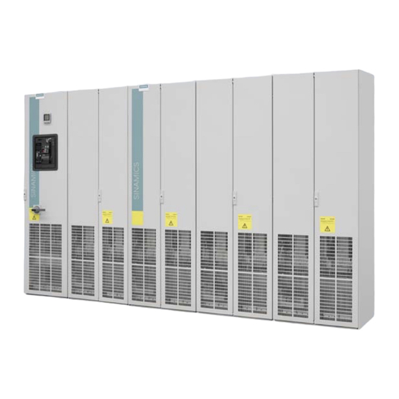
System overview Overview SINAMICS S120 Cabinet Modules are the components of a modular cabinet unit system for multi-axis drives with a central supply infeed and a common DC link busbar, as typically found in paper-making machines, roller mills, test stands, or hoisting gear. - Page 22 System overview 2.1 Overview Figure 2-1 Example of a drive line-up with SINAMICS S120 Cabinet Modules for a multi-motor drive The following table provides an overview of the voltage ranges and power ratings available for the SINAMICS S120 Cabinet Modules:...
-
Page 23: Field Of Application
System overview 2.2 Field of application Field of application The modular SINAMICS S120 Cabinet Modules drive system is used to coordinate multiple motors in a multi-axis drive system. Typical examples include: ● Paper-making machines ● Roller mills ● Hoisting gear ●... -
Page 24: Line Modules
System overview 2.4 Line Modules Line Modules 2.4.1 General information Power is fed to the drive line-up via Line Modules, which generate a DC voltage from the line voltage and, therefore, supply energy to the Motor Modules connected to the DC link. They are suitable for connection to grounded (TN, TT) and non-grounded (IT) systems. - Page 25 System overview 2.4 Line Modules Line Connection Module Load Main Basic Line disconnector contac Module with fuses Motor Module G_D213_DE_00042a Figure 2-2 Line Connection Module with Basic Line Module ≤ 800 A Line Connection Module Basic Line Circuit breaker Module Motor Module G_D213_DE_00043a...
-
Page 26: Smart Line Modules
Interface Modules include the required pre-charging input circuit for the Active Line Module, in addition to a Clean Power Filter. These two components are considered to be an integral unit for SINAMICS S120 Cabinet Modules and are supplied together. For a compact configuration, Line Connection Modules up to input currents of 3,200 A are available. - Page 27 System overview 2.4 Line Modules Line Connection Module Load Active Active Line pass Interface Module disconnector contactor Module with fuses Motor Module G_D213_DE_00046a Figure 2-6 Line Connection Module with Active Interface Module and Active Line Module ≤ 800 A, example frame size HX + HI Line Connection Module Active Active Line...
-
Page 28: Dc Link Components
System overview 2.5 DC link components DC link components Braking Modules enable braking resistors to absorb the regenerative energy produced during drive deceleration, which is then converted into heat. Using a Braking Module and braking resistance it is also possible to brake motors when the power fails. -
Page 29: Motor Modules
Auxiliary Power Supply Modules supply power to the auxiliary power supply system of the SINAMICS S120 Cabinet Modules. The fans of the SINAMICS S120 devices installed in the Cabinet Modules are some of the devices connected to this auxiliary power supply system. In addition, the auxiliary power supply system supplies the electronics modules with external 24 V DC. -
Page 30: Overview Of Options
System overview 2.8 Overview of options Overview of options Table 2- 2 Overview of options Option code Brief description of option Sector-specific version Cranes Customer documentation (circuit diagram, terminal diagram, layout diagram) in DXF format Draft of customer documentation Documentation language: English/French Documentation language: English/Spanish Documentation language: English/Italian Unit acceptance in presence of customer: Visual acceptance... - Page 31 System overview 2.8 Overview of options Option code Brief description of option Line Connection Module for Active Line Modules Line Connection Module for Basic Line Modules Line Connection Module for Smart Line Modules EMERGENCY OFF pushbutton installed in the cabinet door Grounding switch upstream of main breaker Grounding switch downstream of main breaker Holder for ARC detector...
-
Page 32: System Structure
System overview 2.9 System structure Option code Brief description of option One-line label for plant identification, 40 x 80 mm Two-line label for plant identification, 40 x 180 mm Four-line label for plant identification, 40 x 180 mm System structure Line Modules are coupled with the various Motor Modules using prefabricated DC busbar sets with different current load ratings. -
Page 33: System Data
System overview 2.10 System data 2.10 System data General technical system data Electrical data Line voltages and power ranges 380 ... 480 V 3 AC, ±10 % (-15 % < 1 min), 1.6 ... 800 kW 500 ... 690 V 3 AC, ±10 % (-15 % < 1 min), 55 ... 1200 kW Line system configurations TN/TT supplies or isolated-neutral supplies (IT supplies) Line frequency... - Page 34 System overview 2.10 System data Ambient conditions In operation During storage During transport 0 °C Ambient temperature ... +40 °C -25 °C to +55 °C -25 °C to +70 °C -40 °C to +50 °C see derating data from for 24 hours 95 % ...
-
Page 35: Derating Data
Derating data for chassis format 2.11.1.1 General SINAMICS S120 Cabinet Modules as well as the associated system components are dimensioned for an ambient temperature of 40 °C and installation altitudes up to 2000 m above sea level. S120 Cabinet Modules include Basic Line Modules, Smart Line Modules, Active Line Modules and Motor Modules with power units, chassis format including the associated system components, (e.g. -
Page 36: Derating Measures
2.11 Derating data Installation altitudes greater than 2000 to 5000 m above sea level If SINAMICS S120 Cabinet Modules are operated at installation altitudes greater than 2000 m above sea level, then it must be taken into account that with increasing installation altitude, the air pressure and therefore the density of the air decreases. - Page 37 System overview 2.11 Derating data Table 2- 6 Current derating as a function of the ambient temperature (air intake temperature where the air enters the cabinet unit) and installation altitude for cabinet units with degree of protection IP54 Installation altitude Current derating factor above sea level in m at an ambient temperature (air intake temperature) of...
-
Page 38: Derating Data For Booksize Format
40 °C and installation altitudes up to 1000 m above sea level. If SINAMICS S120 Cabinet Modules with power units in the booksize format are operated at ambient temperatures higher than 40 °C and/or... -
Page 39: Mechanical Installation
Mechanical installation Important notes Transport WARNING Please note the following when transporting the cabinet units: • The cabinet units are heavy. Their center of gravity is displaced, and they can be top heavy. • Ensure that the ground at the installation location is strong enough to bear the weight of the cabinet units. - Page 40 Note Notes regarding damage in transit: • Carry out a thorough visual inspection of the SINAMICS S120 Cabinet Modules before accepting the delivery from the shipping company. Pay special attention to transport damage that is not readily apparent but indicated by the tilt and shock indicators.
- Page 41 Mechanical installation 3.1 Important notes Storage The cabinet units must be stored in clean, dry rooms. Temperatures between -25 °C and +55 °C are permissible (class 1K4 to IEC 60721-3-1). Temperature variations greater than 20 K per hour are not permitted. If the cabinet is stored for a prolonged period once it has been unpacked, cover it or take other appropriate measures to ensure that it does not become dirty and that it is protected against environmental influences.
-
Page 42: Mechanical Installation: Checklist
Mechanical installation: Checklist Important safety precautions DANGER To ensure that the SINAMICS S120 Cabinet Modules operate safely and reliably, they must be properly installed and commissioned by qualified personnel, taking into account all the warning notices provided. In particular, the general and national installation and safety guidelines for high-voltage installations (e.g. - Page 43 Mechanical installation 3.2 Mechanical installation: Checklist Item Activity Applicable?/Completed? The crane transport assembly (option M90) installed for delivery must be removed once the transport unit or individual cabinet units have been set down at the final installation location. (→ See the subchapter below titled "Installation", in section "Disassembling the crane transport assembly") Before the cabinet units are finally installed, the wooden pallets supplied with the transport unit must be removed properly.
-
Page 44: Installation
Mechanical installation 3.3 Installation Installation 3.3.1 Important safety precautions DANGER To ensure that the cabinet units operate safely and reliably, they must be properly installed and commissioned by qualified personnel, taking into account all the warning notices provided. In particular, the general and national installation and safety guidelines for high-voltage installations (e.g. - Page 45 Mechanical installation 3.3 Installation The cabinet units are installed in accordance with the dimension drawings supplied. The clearance to be maintained between the top of the cabinet and the ceiling is shown in the diagram below. Additional dimensions must be taken into account for the M06 (cabinet base) and M07 (cable-marshaling compartment) options.
-
Page 46: Requirements On The Levelness Of The Floor
Mechanical installation 3.3 Installation 3.3.2.2 Requirements on the levelness of the floor The foundation at the installation location of the cabinet devices must be level to ensure proper functioning of the cabinet units. ● Care must be taken to ensure that the doors can be opened and closed and that the locking systems work properly. -
Page 47: Shipping And Handling Indicators
Mechanical installation 3.3 Installation 3.3.2.3 Shipping and handling indicators The cabinet units are equipped with tilt and shock indicators to monitor for damage during transit. Figure 3-3 Tilt indicator Figure 3-4 Shock indicator Position of the shipping and handling indicators The tilt indicators are affixed to the top of the cabinet unit inside the doors. - Page 48 Mechanical installation 3.3 Installation Checking the shipping and handling indicators prior to commissioning It is essential to check the shipping and handling indicators prior to commissioning the converter. Figure 3-5 Tilt indicator tripped The tilt indicator provides immediate visible evidence of whether the cabinet units have been handled and stored upright.
-
Page 49: Unpacking The Cabinets
Mechanical installation 3.3 Installation Removing the shipping and handling indicators prior to commissioning CAUTION The shipping and handling indicators must be removed before commissioning the converter. If this is not observed, the transport indicators can cause damage in the unit when the converter is operated. -
Page 50: Lifting The Cabinet Units Off The Transport Pallet And Installing Them
Mechanical installation 3.3 Installation 3.3.3 Lifting the cabinet units off the transport pallet and installing them The applicable local guidelines regarding the transportation of the cabinet from the transport pallet to the installation location must be observed. A crane transport assembly (option M90) can also be fitted on the top of the cabinet. The fixing screws on the transport pallet can be removed from the pallet base without having to raise the cabinet unit. -
Page 51: Disassembling The Crane Transport Assembly
Mechanical installation 3.3 Installation 3.3.4 Disassembling the crane transport assembly With option M90 (crane transport assembly), the Cabinet Modules are equipped with either transport eyebolts or mounting rails. Dismantling The transport eyebolts can be unscrewed and removed. Depending on the length of the cabinet or transport unit, the support rails can have a varying number of fastening screws. -
Page 52: Connection For Side-By-Side Installation Of Cabinet Units
Mechanical installation 3.3 Installation 3.3.6 Connection for side-by-side installation of cabinet units Description An accessories kit is provided with each cabinet or transport unit for the connection of cabinet units in a side-by-side installation. The table below shows the content of this accessories kit and the fixing points for connecting the cabinet units. - Page 53 Mechanical installation 3.3 Installation Assembling 1. Attach the row clamps/row connectors to the appropriate profiles (as shown in the figures above). 2. Insert and tighten the screws and washers. 3. If necessary, reattach the protective covers and doors. Note Installing the top cover or the hood to increase the degree of protection It makes sense to only increase the degree of protection after installation work has been completed, as in some cases, it is easier to access individual elements from the top, with the top cover removed or with the hood removed than from the front.
- Page 54 Mechanical installation 3.3 Installation Cabinet Modules Manual, (GH5), 05/2010, A5E03263538A...
-
Page 55: Electrical Installation
Electrical installation Safety information Required safety precautions before installation work is carried out DANGER The Cabinet Modules are used in industrial high-voltage installations. During operation, this Cabinet Module contains rotating and live parts. For this reason, there is a risk of severe injury or significant material damage if the required covers are removed without authorization, if it is used or operated incorrectly, or if it has not been properly maintained. -
Page 56: Electrical Installation: Checklist
Electrical installation 4.2 Electrical installation: Checklist Electrical installation: Checklist Important safety precautions DANGER The cabinet units are operated with high voltages. All connection work must be carried out when the cabinet is de-energized. All work on the unit must be carried out by trained personnel only. Work on an open unit must be carried out with extreme caution because external supply voltages may be present. - Page 57 Electrical installation 4.2 Electrical installation: Checklist Table 4- 1 Electrical installation: Checklist Item Activity Applicable?/Completed? General information For strain relief, the cables must be clamped on the cable propping bar (C-type mounting bar). When EMC-shielded cables are used, screwed glands that connect the shield to ground with the greatest possible surface area must be provided on the motor terminal box.
- Page 58 Electrical installation 4.2 Electrical installation: Checklist Item Activity Applicable?/Completed? When connecting the braking resistor, the maximum permissible cable lengths between the Braking Module (options L61/L62, L64/L65) and the associated braking resistor must be observed. The resistor is connected at terminals R1 and R2 on the Braking Module. The thermal contact of the braking resistor must be wired up and its signal evaluated by the controller.
- Page 59 Electrical installation 4.2 Electrical installation: Checklist Item Activity Applicable?/Completed? The date of manufacture can be determined from the rating plates of the power components in the "Basic Line Module", "Smart Line Module", "Active Line Module", "Motor Module in chassis format", and "Booksize Cabinet Kit" Cabinet Modules. If the period from the date of manufacture to initial commissioning or the downtime of the power components is shorter than 2 years, the DC link capacitors do not have to be reformed.
- Page 60 Electrical installation 4.2 Electrical installation: Checklist Item Activity Applicable?/Completed? K48, The SMC20 Sensor Module is used for detecting the SMC20 Sensor Module actual motor speed and the path length. The following encoders are supported by the SMC20 Sensor Module: • Incremental sin/cos 1Vpp EnDat absolute encoder •...
-
Page 61: Emc-Compliant Design
Electrical installation 4.3 EMC-compliant design Item Activity Applicable?/Completed? L46, The interlock for the upstream, plant-side main breaker grounding switch must be ensured. upstream of circuit (→ See the chapter titled "Options", section "L46/L47, breaker grounding switch upstream/downstream of circuit breaker") L47, The main breaker cannot be closed when the grounding Grounding switch... -
Page 62: Connections
Electrical installation 4.4 Connections Connections 4.4.1 Connection overview Connection overview The following table shows the connections between the individual Cabinet Modules and their connections. When supplied as transport unit (Option Y11, transport units assembled in the factory), these connections only have to be established between the individual transport units as configured. -
Page 63: Pe Busbar
Electrical installation 4.4 Connections 4.4.2 PE busbar 4.4.2.1 General information Availability PE busbars are included in the following S120 Cabinet Modules: ● Line Connection Modules ● Basic Line Modules ● Smart Line Modules ● Active Line Modules ● Booksize Base Cabinets ●... - Page 64 Electrical installation 4.4 Connections Figure 4-1 Connecting the PE busbar when cabinet units are installed side-by-side Establishing the connection 1. Loosen the 1 x M12 nut of the PE busbar on the 1st cabinet. 2. Remove the nut, washer (1), and screw (3). 3.
-
Page 65: Connection According To The System-Side Grounding Concept
Electrical installation 4.4 Connections 4.4.2.3 Connection according to the system-side grounding concept DANGER Once you have established the connections to the PE busbar in the cabinet and/or established the connections to the PE busbar across more than one cabinet unit, you must establish a connection to the central ground of the entire system. -
Page 66: Dc Busbar
Electrical installation 4.4 Connections 4.4.3 DC busbar 4.4.3.1 General information Availability The DC busbar is always integrated in the following S120 Cabinet Modules and must be ordered as option M80 to M87: ● Basic Line Modules ● Smart Line Modules ●... - Page 67 Electrical installation 4.4 Connections Preparatory steps ● Verify that the cabinet units to be connected have been isolated from the supply. ● Install and secure the cabinet units properly. ● Observe the "five safety rules". ● Allow unimpeded access to the DC busbar (if necessary, remove the protective covers during installation work).
-
Page 68: Auxiliary Power Supply System
Electrical installation 4.4 Connections CAUTION The screws must only be loosened rather than removed because otherwise the nuts could fall into the device. The torque (50 Nm) must be observed to avoid excessive heating of the terminal contacts during operation. All jumpers of the DC busbar must always be connected in busbar systems. - Page 69 Electrical installation 4.4 Connections Ideally, these voltages are generated by an Auxiliary Power Supply Module. Other ways to supply power is to use option K76 "Auxiliary voltage generating unit in the Line Connection Module" or to feed the auxiliary voltages to the auxiliary power supply system from an external source.
- Page 70 Electrical installation 4.4 Connections Auxiliary power module Figure 4-4 Auxiliary power module with terminal blocks -X100, -X101 and 24 V DC fuse Table 4- 3 X100, terminal block for tapping the auxiliary voltages Terminal Designation Voltage tap Rated current Line voltage (for fan supply via transformer): max.
- Page 71 Electrical installation 4.4 Connections Table 4- 4 X101, terminal block for routing the auxiliary voltage connecting cables Terminal Designation Assigned voltages Rated current Line voltage (for fan supply via transformer): Max. 80 A 380 to 480 V 2 AC or •...
-
Page 72: Connection Overview
Electrical installation 4.4 Connections Note External infeed An external customer infeed to the auxiliary power supply system can be connected at terminal block -X100 of the Line Connection Module. Fuse A 10 A-fuse is incorporated in the auxiliary power modules to protect the 24 V DC-auxiliary voltage. -
Page 73: Connection For Side-By-Side Installation Of Cabinet Units
Electrical installation 4.4 Connections 4.4.4.3 Connection for side-by-side installation of cabinet units Description Prefabricated cables for connecting the auxiliary power modules are attached to the -X101 terminal block of the module in each cabinet. If the cabinets are delivered as single units, these must be routed to the next module and attached to the appropriate terminals of the -X101 terminal block. -
Page 74: Connecting To The Infeed
Electrical installation 4.4 Connections Establishing the connection CAUTION Take care not to cut yourself on the sharp edges inside the cabinet when connecting the auxiliary power supply system. 1. Disconnect the cabinet from the power supply. 2. Observe the "five safety rules". 3. -
Page 75: Connecting The Motor Cables
Electrical installation 4.4 Connections 4.4.5 Connecting the motor cables Preparatory steps ● Install and secure the cabinet units properly. ● Disconnect the cabinet units from the power supply. ● Make sure that all the necessary safety measures have been taken at the installation location. - Page 76 Electrical installation 4.4 Connections Frame sizes FX and GX Frame sizes HX and JX -U2/-T1 -V2/-T2 -W2/-T3 -U2/-T1 -V2/-T2 -W2/-T3 Connecting the motor cables 1. Open the cabinet and remove the covers in front of the connection panel for motor cables (terminals U2/T1, V2/T2, W2/T3;...
- Page 77 Electrical installation 4.4 Connections Note For the position of the connections for motor cables, see the layout diagrams included on the customer DVD supplied with the device. The motor ground should be fed back directly to the cabinet (PE busbar) and connected. Connection cross sections Refer to the "Technical data"...
-
Page 78: Line Supply Connections
Electrical installation 4.4 Connections 4.4.6 Line supply connections Line Connection Modules The line supply is connected in the Line Connection Module at terminal X1. Table 4- 10 Line supply connection, Line Connection Modules Terminals Technical data U1/L1, V1/L2, W1/L3 Voltage: 3 AC power input 3 AC 380 V -10 % to 3 AC 480 V +10 % (-15 % <... - Page 79 Electrical installation 4.4 Connections Figure 4-6 Setting terminals for the fan transformers (380 to 480 V 2 AC) Figure 4-7 Setting terminals for the fan transformers (500 to 690 V 2 AC) The line-voltage assignments for making the appropriate setting on the fan transformer are indicated in the following table.
-
Page 80: Operating Cabinet Modules On An Isolated-Neutral Supply System (It System)
Electrical installation 4.4 Connections Table 4- 11 Line voltage assignments for setting the fan transformer (380 to 480 V 2 AC) Line voltage Fan transformer tap (-T1/-T2 –T10, -T20) 380 V ± 10% 380 V 400 V ± 10% 400 V 440 V ±... - Page 81 Electrical installation 4.4 Connections Basic Line Modules When a Basic Line Module is operated from an isolated line supply (IT line supply), the connection bar for the interference-suppression capacitor must be removed. Figure 4-8 Removing the connection bar to the interference suppression capacitor in the Basic Line Module for frame size FB Cabinet Modules Manual, (GH5), 05/2010, A5E03263538A...
- Page 82 Electrical installation 4.4 Connections Figure 4-9 Removing the connection bar to the interference suppression capacitor in the Basic Line Module for frame size GB Cabinet Modules Manual, (GH5), 05/2010, A5E03263538A...
- Page 83 Electrical installation 4.4 Connections Smart Line Modules When the device is operated on an isolated line supply (IT line supply), the connection bar to the interference suppression capacitor must be removed (e.g.: "1" in figure below). With frame sizes HX and JX, you must remove the left-hand fan before removing the connection bar (see chapter "Replacing components").
- Page 84 Electrical installation 4.4 Connections Active Line Modules If the cabinet unit is operated on an ungrounded line supply/IT line supply, the connection bar for the interference suppression capacitor of the Active Interface Module (-A2) must be removed. Figure 4-11 Removing the connection bar to the interference suppression capacitor in the Active Interface Module for frame size FX Cabinet Modules Manual, (GH5), 05/2010, A5E03263538A...
- Page 85 Electrical installation 4.4 Connections Figure 4-12 Removing the connection bar to the interference suppression capacitor in the Active Interface Module for frame size GX Cabinet Modules Manual, (GH5), 05/2010, A5E03263538A...
- Page 86 Electrical installation 4.4 Connections Figure 4-13 Removing the connection bar to the interference suppression capacitor in the Active Interface Module for frame size HX Cabinet Modules Manual, (GH5), 05/2010, A5E03263538A...
- Page 87 Electrical installation 4.4 Connections Figure 4-14 Removing the connection bar to the interference suppression capacitor in the Active Interface Module for frame size JX Cabinet Modules Manual, (GH5), 05/2010, A5E03263538A...
-
Page 88: Signal Connections
Electrical installation 4.4 Connections 4.4.9 Signal connections Note The factory setting and description of the customer terminal blocks are documented in the circuit diagrams. The location of the customer terminal blocks of the individual Cabinet Modules is documented in the layout diagrams. The interfaces or customer terminal blocks are documented for the respective Cabinet Modules. - Page 89 Electrical installation 4.4 Connections Basic rules for cable routing The Cabinet Modules are delivered pre-wired. The following basic rules must always be observed for all Cabinet Modules should any additional cabling and wiring or connection work be necessary. ● Observe EMC guidelines. ●...
-
Page 90: Cable Routing For Line Connection Modules
Electrical installation 4.4 Connections 4.4.11.2 Cable routing for Line Connection Modules For the Line Connection Modules, the customer must carry out the following cabling or connection work: Table 4- 13 Checklist for cabling or connection work for Line Connection Modules Cable routing Completed? Cable for the line supply connection (L1, L2, L3, PE) - Page 91 Electrical installation 4.4 Connections Cable routing for connecting to the supply infeed Frame size: GL/HL KL/LL 1. Feed the infeed cable into the cabinet from the bottom. 2. Connect the PE cable to the grounding bar. 3. Feed the cable up through the cabinet to terminal block -X1. 4.
- Page 92 Electrical installation 4.4 Connections Signal cables Frame size: GL/HL KL/LL 1. Feed the signal cables into the cabinet from the bottom left. 2. Feed the signal cables up through the cabinet to terminal blocks -X30, -X40, and -X50. 3. Fasten the signal cables at suitable points. 4.
-
Page 93: Cable Routing For Basic Line Modules
Electrical installation 4.4 Connections 4.4.11.3 Cable routing for Basic Line Modules For the Basic Line Modules, the customer must carry out the following cabling or connection work: Table 4- 14 Checklist for cabling or connection work for Basic Line Modules Cable routing Completed? PROFIBUS cables to the Control Unit... - Page 94 6. Use cable ties to secure the cable at suitable points. 7. Connect the cable to the Control Unit. (→See SINAMICS S120 Manual GH1 Control Units) Cabinet Modules Manual, (GH5), 05/2010, A5E03263538A...
- Page 95 Electrical installation 4.4 Connections Cable routing for DRIVE-CLiQ connections and signal cables Frame size: 1. Feed the DRIVE-CLiQ/signal cable into the cabinet from the bottom left. 2. Use cable ties to secure the cable at suitable points. 3. Feed the cable up through the cabinet and, when it reaches the Control Unit, guide it up and to the right towards the Control Unit.
- Page 96 Electrical installation 4.4 Connections Cable routing to the customer terminal block -X55 Frame size: 1. Feed the cable for the customer terminal block into the cabinet from the bottom left. 2. Remove approx. 3 cm of the cable insulation at the level of the shield plate in the lower part of the cabinet and attach the cable.
-
Page 97: Cable Routing For Smart Line Modules
Electrical installation 4.4 Connections 4.4.11.4 Cable routing for Smart Line Modules For the Smart Line Modules, the customer must carry out the following cabling or connection work: Table 4- 15 Checklist for cabling or connection work for Smart Line Modules Cable routing Completed? PROFIBUS cables to the Control Unit... - Page 98 6. Use cable ties to secure the cable at suitable points. 7. Connect the cable to the Control Unit (→See SINAMICS S120 Manual GH1 Control Units) Cabinet Modules Manual, (GH5), 05/2010, A5E03263538A...
- Page 99 Electrical installation 4.4 Connections Cable routing for DRIVE-CLiQ connections and signal cables to the Control Unit Frame size: 1. Feed the DRIVE-CLiQ/signal cable into the cabinet from the bottom left. 2. Use cable ties to secure the cable at suitable points. 3.
- Page 100 Electrical installation 4.4 Connections Cable routing to the customer terminal block -X55 Frame size: 1. Feed the cable for the customer terminal block into the cabinet from the bottom left. 2. Use cable ties to secure the cable at suitable points. 3.
-
Page 101: Cable Routing For Active Line Modules
Electrical installation 4.4 Connections 4.4.11.5 Cable routing for Active Line Modules For the Active Line Modules, the customer must carry out the following cabling or connection work: Table 4- 16 Checklist for cabling or connection work for Active Line Modules Cable routing Completed? PROFIBUS cables to the Control Unit... - Page 102 6. Use cable ties to secure the cable at suitable points. 7. Connect the cable to the Control Unit (→See SINAMICS S120 Manual GH1 Control Units) Cabinet Modules Manual, (GH5), 05/2010, A5E03263538A...
- Page 103 6. Use cable ties to secure the cable at suitable points. 7. Connect the cable to the Control Unit (→See SINAMICS S120 Manual GH1 Control Units) Cabinet Modules Manual, (GH5), 05/2010, A5E03263538A...
- Page 104 Electrical installation 4.4 Connections Cable routing for DRIVE-CLiQ connections and signal cables, frame sizes FX+FI and GX+GI Frame size: FX+FI GX+GI 1. Feed the cable for the DRIVE-CLiQ/signal cables into the cabinet from the bottom left. 2. Use cable ties to secure the cable at suitable points. 3.
- Page 105 Electrical installation 4.4 Connections Cable routing for DRIVE-CLiQ connections and signal cables, frame sizes HX+HI and JX+JI Frame size: HX+HI JX+JI 1. Feed the cable for the DRIVE-CLiQ/signal cables into the cabinet from the bottom left. 2. Use cable ties to secure the cable at suitable points. 3.
- Page 106 Electrical installation 4.4 Connections Cable routing to customer terminal block -X55, frame sizes FX+FI and GX+GI Frame size: FX+FI GX+GI 1. Feed the cable for the customer terminal block into the cabinet from the bottom right (frame size FX+FI) or bottom left (frame size GX+GI). 2.
- Page 107 Electrical installation 4.4 Connections Cable routing for customer terminal block –X55, frame sizes HX+HI and JX+JI Frame size: HX+HI JX+JI 1. Feed the cable for the customer terminal block into the cabinet from the bottom left. 2. Use cable ties to secure the cable at suitable points. 3.
-
Page 108: Cable Routing For Booksize Base Cabinets And Booksize Cabinet Kit
Electrical installation 4.4 Connections 4.4.11.6 Cable routing for Booksize Base Cabinets and Booksize Cabinet Kit Note The procedure is the same as that for the Cabinet Modules Motor Module in chassis format. (→ See the Section titled "Cable routing for Motor Modules in chassis format") Cable routing of motor cable Note The motor cables are easy to connect to terminals in the lower part of the customer... - Page 109 6. Use cable ties to secure the cable at suitable points. 7. Connect the cable to the Control Unit. (→See SINAMICS S120 Manual GH1 Control Units) Cabinet Modules Manual, (GH5), 05/2010, A5E03263538A...
- Page 110 Electrical installation 4.4 Connections Cable routing for DRIVE-CLiQ connections and signal cables to the Control Unit Frame size: FX+GX HX+JX 1. Feed the DRIVE-CLiQ/signal cable into the cabinet from the bottom left. 2. Use cable ties to secure the cable at suitable points. 3.
- Page 111 Electrical installation 4.4 Connections Cable routing of signal cables to the customer terminal block –X55 Frame size: FX+GX HX+JX 1. Feed the cable for the customer terminal block into the cabinet from the bottom left. 2. Use cable ties to secure the cable at suitable points. 3.
- Page 112 Electrical installation 4.4 Connections Cable routing for the "Safe Torque off" and “Safe Stop 1” functions Note The procedure is the same as that for the customer terminal block. Connect the cable to the terminals to control the functions. (→ See the chapter titled "Options", section "K82, terminal module for activating "Safe Torque Off"...
- Page 113 Electrical installation 4.4 Connections Cable routing for signal cables to SMC10/20/30 Sensor Module Frame size: FX+GX HX+JX 1. Feed the cable for the customer terminal block into the cabinet from the bottom left. 2. Remove approx. 3 cm of the insulation at the level of the shield plate in the lower part of the cabinet and attach the cable.
- Page 114 Electrical installation 4.4 Connections Cable routing for motor connection Frame size: FX+GX HX+JX 1. Feed the cable into the cabinet from below. 2. Feed the cable up through the cabinet to the motor connections -U2/-T1, -V2/-T2, -W2/- 3. Connect the cable to the connections. Cabinet Modules Manual, (GH5), 05/2010, A5E03263538A...
-
Page 115: Cable Routing For Central Braking Modules
Electrical installation 4.4 Connections 4.4.11.8 Cable routing for Central Braking Modules Cable routing to the braking resistor Central Braking Module 1. Feed the cable into the cabinet from below. 2. Feed the cable up and behind the PE busbar to the braking resistor terminals. 3. - Page 116 Electrical installation 4.4 Connections Cable routing to terminal block -X2 Central Braking Module 1. Feed the cable into the cabinet from the bottom left. 2. Guide the cable up and, when it reaches the level of terminal -X2, guide it to the right. 3.
-
Page 117: Cable Routing For Auxiliary Power Supply Modules
Electrical installation 4.4 Connections 4.4.11.9 Cable routing for Auxiliary Power Supply Modules Cable routing for connecting to the supply infeed Auxiliary Power Supply Module 1. Feed the cable into the cabinet from the bottom right. 2. Guide the cable up and, when it reaches the level of the line connection, guide it to the left. - Page 118 Electrical installation 4.4 Connections Cable routing for signal cables to terminal blocks -X45, -X46, -X47 Auxiliary Power Supply Module 1. Feed the cable into the cabinet from the bottom left. 2. Guide the cable up and, when it reaches the terminal blocks, to the right. 3.
-
Page 119: Cabinet Modules
Cabinet Modules Line Connection Modules 5.1.1 General information DANGER Hazardous voltages are present in certain parts of this equipment during operation of the cabinet unit. Only qualified personnel may work on the cabinet. Such personnel must be thoroughly familiar with all the warnings and maintenance procedures for the cabinet described in the documentation provided. -
Page 120: Description
Cabinet Modules 5.1 Line Connection Modules 5.1.2 Description Note Refer to the layout diagrams and circuit diagrams provided on the customer DVD supplied with the device for the arrangement of components and interfaces, and for wiring. Power is fed to the drive line-up via Line Modules, which generate a DC voltage from the line voltage and, therefore, supply energy to the Motor Modules connected to the DC link. - Page 121 Cabinet Modules 5.1 Line Connection Modules C /L + D /L - - Q 1 - F 1 - F 2 -F 3 - T 10 -Q 10 -B 101 - T 24 - Q 2 /- Q 3/ -Q 4 U1 /L1 V1/ L2 W 1 /L 3...
- Page 122 Cabinet Modules 5.1 Line Connection Modules C/ L + D /L - -Q 1 -T 10 - Q 10 - F 71 - F 72 -F 73 -B 101 - T 24 - X1 - T111 -T 10 - T 112 U 1 /L1 V1 /L 2 W 1 /L3...
-
Page 123: Fuse Switch Disconnector (Input Current ≤ 800 A)
Cabinet Modules 5.1 Line Connection Modules 5.1.2.1 Fuse switch disconnector (input current ≤ 800 A) Up to 800 A, a switch disconnector with integrated fuses is incorporated. X50 "Fuse switch disconnector" checkback contact Table 5- 2 Terminal block X50 "Fuse switch disconnector" checkback contact Terminal Designation Technical data... - Page 124 Cabinet Modules 5.1 Line Connection Modules Table 5- 4 Factory setting of the overcurrent release on Line Connection Modules for Smart Line Modules Order number Order number Input current Overload trip Short-time Short-circuit Line Connection Smart Line Module Line Module delayed short- release delay Module...
-
Page 125: Terminal Block -X40 External 230 V Ac Auxiliary Infeed
Cabinet Modules 5.1 Line Connection Modules X50 "circuit breaker" checkback contact Table 5- 6 Terminal block X50 "Circuit-breaker" checkback contact Terminal Designation Technical data "Fuse switch disconnector" checkback contacts Max. load current: 3 A Max. switching voltage: 250 V AC Max. -
Page 126: Versions Of Line Connection Modules
Cabinet Modules 5.1 Line Connection Modules 5.1.3 Versions of Line Connection Modules Different versions to suit specific input currents are available: ● Units ≤ 800 A are equipped with a main breaker with fuse switch disconnector ● Units > 800 A are equipped with a fixed-mounted circuit breaker (draw-out circuit breaker is available as option) Line Connection Modules come in the following versions (specified by an option code) according to the type of the Line Module that is being fed:... -
Page 127: Version L43 For Basic Line Modules
Cabinet Modules 5.1 Line Connection Modules -Q10 Pre-charging 3WL1 -R 1 U1_1 U1/L1 V1_1 V1/L2 W1_1 W1/L3 -R 1.1 U1_2 V1_2 W1_2 Figure 5-5 Connection example: Line Connection Module ≥2000 A for connection to Active Line Modules in parallel connection, option L42 5.1.3.2 Version L43 for Basic Line Modules When Basic Line Modules are used, a line reactor is incorporated as a standard feature. - Page 128 Cabinet Modules 5.1 Line Connection Modules -Q10 Pre-charging 3WL1 U1/L1 U1/L1 V1/L2 V1/L2 W1/L3 W1/L3 Figure 5-8 Connection example: Line Connection Module >1800 A, <2000 A for connection to Basic Line Modules, option L43 If Basic Line Modules that are fed via a common Line Connection Module are connected in parallel, line reactors are generally incorporated in the Line Connection Module.
-
Page 129: Version L44 For Smart Line Modules
Cabinet Modules 5.1 Line Connection Modules 5.1.3.3 Version L44 for Smart Line Modules U1/L1 U1/L1 V1/L2 V1/L2 W1/L3 W1/L3 Figure 5-10 Connection example: Line Connection Module ≤800 A for connection to Smart Line Modules, option L44 -Q10 3WL1 U1/L1 U1/L1 V1/L2 V1/L2 W1/L3... -
Page 130: Options
Cabinet Modules 5.1 Line Connection Modules 5.1.4 Options Note The individual options are described in the chapter titled "Options". Electrical options Component Option Main contactor (for Line Connection Modules ≤ 800 A) No line reactor for Basic Line Modules Draw-out circuit breaker (for Line Connection Modules > 800 A) Line current transformer Line Connection Module for Active Line Modules Line Connection Module for Basic Line Modules... -
Page 131: Technical Data
Cabinet Modules 5.1 Line Connection Modules 5.1.5 Technical data Table 5- 9 Technical data for Line Connection Modules, 3 AC 380 ... 480 V, part I Order no. 6SL3700- 0LE32- 0LE34- 0LE36- 0LE38- 0LE41- 5AA3 0AA3 3AA3 0AA3 0AA3 Infeed/regenerative feedback current - Rated current I 1000 Power demand 230 V AC... - Page 132 Cabinet Modules 5.1 Line Connection Modules Table 5- 10 Technical data for Line Connection Modules, 3 AC 380 ... 480 V, part II Order no. 6SL3700- 0LE41- 0LE41- 0LE42- 0LE42- 0LE42- 0LE43- 3AA3 6AA3 0AA3 0BA3 5BA3 2BA3 Infeed/regenerative feedback current - Rated current I 1250 1600...
- Page 133 Cabinet Modules 5.1 Line Connection Modules Table 5- 11 Technical data for Line Connection Modules, 3 AC 500 ... 690 V, part I Order no. 6SL3700- 0LG32- 0LG34- 0LG36- 0LG38- 0LG41- 8AA3 0AA3 3AA3 0AA3 0AA3 Infeed/regenerative feedback current - Rated current I 1000 Power demand 230 V AC - Inrush current...
- Page 134 Cabinet Modules 5.1 Line Connection Modules Table 5- 12 Technical data for Line Connection Modules, 3 AC 500 ... 690 V, part II Order no. 6SL3700- 0LG41- 0LG41- 0LG42- 0LG42- 0LG42- 3AA3 6AA3 0BA3 2BA3 5BA3 Infeed/regenerative feedback current - Rated current I 1250 1600 2000...
-
Page 135: Basic Line Modules
Cabinet Modules 5.2 Basic Line Modules Basic Line Modules 5.2.1 General information DANGER Hazardous voltages are present in certain parts of this equipment during operation of the cabinet unit. Only qualified personnel may work on the cabinet. Such personnel must be thoroughly familiar with all the warnings and maintenance procedures for the cabinet described in the documentation provided. - Page 136 Cabinet Modules 5.2 Basic Line Modules Integration Basic Line Module Figure 5-13 Connection example for Basic Line Modules (frame size FB and GB) Note X9 terminal assignment for the Basic Line Module (frame size GD) For the Basic Line Modules, frame size GD, equipped with diode bridge •...
- Page 137 Cabinet Modules 5.2 Basic Line Modules Configuration In Basic Line Modules of frame sizes FB and GB, a fully-controlled thyristor bridge is used to pre-charge the Basic Line Module and the connected DC link. The thyristors normally operate with a trigger delay angle of 0 °. Basic Line Modules of type GD for 900 kW (400 V) or 1500 kW (690 V) feature a diode bridge.
- Page 138 Cabinet Modules 5.2 Basic Line Modules - F19 -F 19 C /L + C /L + F _Schienen _G 600 -Q 50 - F21 -F 21 - X50 - F 20 - F 20 - F23 - F 22 D /L - D /L - - F 22 - F 24...
- Page 139 Cabinet Modules 5.2 Basic Line Modules Parallel connection of Basic Line Modules to increase power rating A pair of Basic Line Modules is available for creating drive line-ups with more power. These modules can be operated on a common Line Connection Module and are arranged to the right and left of the Line Connection Module.
-
Page 140: Interfaces
Cabinet Modules 5.2 Basic Line Modules 5.2.3 Interfaces Table 5- 13 Terminal strip X41 EP terminals / temperature sensor connection Terminal Function Technical data EP M1 (Enable Pulses) Supply voltage: 24 V DC (20.4 ... 28.8 V) Current consumption: 10 mA EP +24 V (Enable Pulses) - Temp Temperature sensor connection:... -
Page 141: Options
Cabinet Modules 5.2 Basic Line Modules 5.2.4 Options Note The individual options are described in the chapter titled "Options". Electrical options Component Option CBC10 Communication Board CBE20 Communication Board AOP30 operator panel Control Unit CU320-2 PROFIBUS Performance extension 1 for CU320-2 Use in the first environment to EN 61800-3, category C2 (TN/TT line supplies) Holder for ARC detector... -
Page 142: Technical Data
Cabinet Modules 5.2 Basic Line Modules 5.2.5 Technical data Table 5- 14 Technical data for Basic Line Modules, 3 AC 380 ... 480 V Order no. 6SL3730- 1TE34- 1TE35- 1TE38- 1TE41- 1TE41- 1TE41- 2AA3 3AA3 2AA3 2AA3 5AA3 8AA3 for parallel connection, - attached to Line Connection Module on ...-2BA3 ...-5BA3... - Page 143 Cabinet Modules 5.2 Basic Line Modules Order no. 6SL3730- 1TE34- 1TE35- 1TE38- 1TE41- 1TE41- 1TE41- 2AA3 3AA3 2AA3 2AA3 5AA3 8AA3 Weight (standard version) 320/440/480 Frame size The base load current I is based on a duty cycle of 150 % for 60 s or I for 5 s with a duty cycle duration of 300 s.
- Page 144 Cabinet Modules 5.2 Basic Line Modules Table 5- 15 Technical data for Basic Line Modules, 3 AC 500 ... 690 V Order no. 6SL3730- 1TG33- 1TG34- 1TG36- 1TG41- 1TG41- 1TG41- 0AA3 3AA3 8AA3 1AA3 4AA3 8AA3 for parallel connection, - Attached to Line Connection Module on ...-2BA3 ...-4BA3 ...-8BA3...
- Page 145 Cabinet Modules 5.2 Basic Line Modules Order no. 6SL3730- 1TG33- 1TG34- 1TG36- 1TG41- 1TG41- 1TG41- 0AA3 3AA3 8AA3 1AA3 4AA3 8AA3 Weight (standard version) 320/440/480 Frame size The base load current I is based on a duty cycle of 150 % for 60 s or I for 5 s with a duty cycle duration of 300 s.
-
Page 146: Smart Line Modules
Cabinet Modules 5.3 Smart Line Modules Smart Line Modules 5.3.1 General information DANGER Hazardous voltages are present in certain parts of this equipment during operation of the cabinet unit. Only qualified personnel may work on the cabinet. Such personnel must be thoroughly familiar with all the warnings and maintenance procedures for the cabinet described in the documentation provided. - Page 147 Cabinet Modules 5.3 Smart Line Modules Integration Cabinet Module DC busbar X400 X401 X402 X500 Smart -X41 Line READY Module +24 V EP M Cabinet Module Voltage Sensing Module Line Connection Module P24 V Control 230 V AC bypass- Internal contactor Power supply Checkback signal...
- Page 148 Cabinet Modules 5.3 Smart Line Modules Configuration IGBTs (fundamental frequency-switched) are used as power semiconductors of the Smart Line Modules. Because this reduces switching losses, high current utilization of the power units can be achieved. The current flows in the direction of the infeed via the freewheeling diodes of the IGBTs. While a diode is conducting, the anti-parallel IGBT is also activated.
- Page 149 Cabinet Modules 5.3 Smart Line Modules C /L + D /L - - T 30 .X21 -T 2 - F 1 - F 2 - E1 - X9 - T 10 - E240 - X55 - R 1 Figure 5-16 Configuration example for Smart Line Modules (frame size GX) Cabinet Modules Manual, (GH5), 05/2010, A5E03263538A...
- Page 150 Cabinet Modules 5.3 Smart Line Modules C /L + D /L - -T 30 .X 21 - T 2 -F 1 -F 3 -F 2 -F 4 - E2 -E 3 - E4 -X 9 -T 20 - T 10 -X55 - E241 Figure 5-17...
- Page 151 Cabinet Modules 5.3 Smart Line Modules Parallel connection of Smart Line Modules to increase power rating Up to four Smart Line Modules with the same power rating can be connected in parallel in order to increase power. Smart Line Modules with "mirror-image" power connections enable the parallel connection of these modules in a compact configuration.
-
Page 152: Interfaces
Cabinet Modules 5.3 Smart Line Modules 5.3.3 Interfaces Table 5- 16 Terminal strip X41 EP terminals / temperature sensor connection Terminal Function Technical data EP M1 (Enable Pulses) Supply voltage: 24 V DC (20.4 V – 28.8 V) Current consumption: 10 mA EP +24 V (Enable Pulses) - Temp Temperature sensor connection:... -
Page 153: Options
Cabinet Modules 5.3 Smart Line Modules 5.3.4 Options Note The individual options are described in the chapter titled "Options". Electrical options Component Option CBC10 Communication Board CBE20 Communication Board AOP30 operator panel Control Unit CU320-2 PROFIBUS Performance extension 1 for CU320-2 Use in the first environment to EN 61800-3, category C2 (TN/TT line supplies) Without line reactor... -
Page 154: Technical Data
Cabinet Modules 5.3 Smart Line Modules 5.3.5 Technical data Table 5- 17 Technical data for Smart Line Modules, 3 AC 380 ... 480 V Order no. 6SL3730- 6TE35- 6TE37- 6TE41- 6TE41- 6TE41- 5AA3 3AA3 1AA3 3AA3 7AA3 for parallel connection, - attached to Line Connection Module on ...-1BA3 ...-3BA3... - Page 155 Cabinet Modules 5.3 Smart Line Modules Order no. 6SL3730- 6TE35- 6TE37- 6TE41- 6TE41- 6TE41- 5AA3 3AA3 1AA3 3AA3 7AA3 Weight (standard version) Frame size The base load current I is based on a duty cycle of 150 % for 60 s or I for 5 s with a duty cycle duration of 300 s.
- Page 156 Cabinet Modules 5.3 Smart Line Modules Table 5- 18 Technical data for Smart Line Modules, 3 AC 500 ... 690 V Order no. 6SL3730- 6TG35- 6TG38- 6TG41- 6TG41- 5AA3 8AA3 2AA3 7AA3 for parallel connection, - Attached to Line Connection Module on ...-8BA3 ...-2BA3 ...-7BA3...
- Page 157 Cabinet Modules 5.3 Smart Line Modules Order no. 6SL3730- 6TG35- 6TG38- 6TG41- 6TG41- 5AA3 8AA3 2AA3 7AA3 Weight (standard version) Frame size The base load current I is based on a duty cycle of 150 % for 60 s or I for 5 s with a duty cycle duration of 300 s.
-
Page 158: Active Line Modules
Cabinet Modules 5.4 Active Line Modules Active Line Modules 5.4.1 General information DANGER Hazardous voltages are present in certain parts of this equipment during operation of the cabinet unit. Only qualified personnel may work on the cabinet. Such personnel must be thoroughly familiar with all the warnings and maintenance procedures for the cabinet described in the documentation provided. - Page 159 Cabinet Modules 5.4 Active Line Modules Integration Active Active Interface Line Module Module Figure 5-18 Connection example for Active Line Modules (frame size FI/FX and GI/GX) Cabinet Modules Manual, (GH5), 05/2010, A5E03263538A...
- Page 160 Cabinet Modules 5.4 Active Line Modules Active Active Interface Line Module Module Figure 5-19 Connection example for Active Line Modules (frame size HI/HX and JI/JX) Cabinet Modules Manual, (GH5), 05/2010, A5E03263538A...
- Page 161 Cabinet Modules 5.4 Active Line Modules Configuration Active Line Modules are always operated together with an Active Interface Module, which contains the associated Clean Power Filter and pre-charging circuit. The included line filter enables compliance with the EMC requirements for the "second environment". Note The configuration examples of the individual Active Line Modules are used to illustrate the positioning of the factory-fitted components.
- Page 162 Cabinet Modules 5.4 Active Line Modules C /L + D /L - AI _G -T 30 .X 21 - F1 - F 2 -X 630 -E10 - X609 - E1 -K 1 - T10 -X 9 - X55 G r undblech AI -X 5 -E 241 - E240...
- Page 163 Cabinet Modules 5.4 Active Line Modules C /L + D /L - -R 2 -K 4 - K101 - X609 - E10 Figure 5-21 Configuration examples for Active Interface Modules (frame size JI) Cabinet Modules Manual, (GH5), 05/2010, A5E03263538A...
- Page 164 Cabinet Modules 5.4 Active Line Modules C /L + D /L - -T 30 .X 21 -T 2 -F 1 /3 -F 2 /4 - E3 -E 2 - T 20 -T 10 -X 55 - E241 - E240 Figure 5-22 Configuration examples for Active Line Modules (frame size JX) Cabinet Modules Manual, (GH5), 05/2010, A5E03263538A...
- Page 165 Cabinet Modules 5.4 Active Line Modules Parallel connection of Active Line Modules to increase power rating Active Line Modules are available for creating drive line-ups with more power. These modules can be operated in parallel on a common Line Connection Module and are arranged to the right and left of the Line Connection Module.
-
Page 166: Interfaces
Cabinet Modules 5.4 Active Line Modules 5.4.3 Interfaces Table 5- 19 Terminal strip X41 EP terminals / temperature sensor connection Terminal Function Technical data EP M1 (Enable Pulses) Supply voltage: 24 V DC (20.4 V – 28.8 V) Current consumption: 10 mA EP +24 V (Enable Pulses) - Temp Temperature sensor connection:... -
Page 167: Options
Cabinet Modules 5.4 Active Line Modules 5.4.4 Options Note The individual options are described in the chapter titled "Options". Electrical options Component Option CBC10 Communication Board CBE20 Communication Board AOP30 operator panel Control Unit CU320-2 PROFIBUS Performance extension 1 for CU320-2 Use in the first environment to EN 61800-3, category C2 (TN/TT line supplies) Holder for ARC detector... -
Page 168: Technical Data
Cabinet Modules 5.4 Active Line Modules 5.4.5 Technical data Table 5- 20 Technical data for Active Line Modules (including Active Interface Module), 3 AC 380 ... 480 V, part I Order No. 6SL3730- 7TE32- 7TE32- 7TE33- 7TE35- 1BA3 6BA3 8BA3 0BA3 for parallel connection, - attached to Line Connection Module on left side... - Page 169 Cabinet Modules 5.4 Active Line Modules Order No. 6SL3730- 7TE32- 7TE32- 7TE33- 7TE35- 1BA3 6BA3 8BA3 0BA3 Weight (standard version) Frame size FX + FI FX + FI GX + GI GX + GI The base load current I is based on a duty cycle of 150 % for 60 s or I for 5 s with a duty cycle duration of 300 s.
- Page 170 Cabinet Modules 5.4 Active Line Modules Table 5- 21 Technical data for Active Line Modules (including Active Interface Module), 3 AC 380 ... 480 V, part II Order no. 6SL3730- 7TE36- 7TE38- 7TE41- 7TE41- 1BA3 4BA3 0BA3 4BA3 for parallel connection, - attached to Line Connection Module on left side ...-0BC3 ...-4BC3...
- Page 171 Cabinet Modules 5.4 Active Line Modules Table 5- 22 Technical data for Active Line Modules (including Active Interface Module), 3 AC 500 ... 690 V Order no. 6SL3730- 7TG35- 7TG37- 7TG41- 7TG41- 8BA3 4BA3 0BA3 3BA3 for parallel connection, - Attached to Line Connection Module on left side ...-4BC3 ...-0BC3 ...-3BC3...
- Page 172 Cabinet Modules 5.4 Active Line Modules Order no. 6SL3730- 7TG35- 7TG37- 7TG41- 7TG41- 8BA3 4BA3 0BA3 3BA3 Weight (standard version) 1360 1360 1360 Frame size HX + HI JX + JI JX + JI JX + JI The base load current I is based on a duty cycle of 150 % for 60 s or I for 5 s with a duty cycle duration of 300 s.
-
Page 173: Booksize Format Motor Modules
Cabinet Modules 5.5 Booksize format Motor Modules Booksize format Motor Modules 5.5.1 General information DANGER Hazardous voltages are present in certain parts of this equipment during operation of the cabinet unit. Only qualified personnel may work on the cabinet. Such personnel must be thoroughly familiar with all the warnings and maintenance procedures for the cabinet described in the documentation provided. - Page 174 Cabinet Modules 5.5 Booksize format Motor Modules Integration Figure 5-23 Connection example for Single Motor Modules in Booksize Cabinet Kit format ① Temperature sensor connection for motors without DRIVE-CLiQ interface ② Required for Safety Integrated ③ Fan module for rated output currents from 132 A and 200 A Cabinet Modules Manual, (GH5), 05/2010, A5E03263538A...
- Page 175 Cabinet Modules 5.5 Booksize format Motor Modules Figure 5-24 Connection example for Double Motor Modules in Booksize Cabinet Kit format ① Temperature sensor connection for motors without a DRIVE-CLiQ interface ② Required for Safety Integrated Cabinet Modules Manual, (GH5), 05/2010, A5E03263538A...
- Page 176 Cabinet Modules 5.5 Booksize format Motor Modules Configuration Motor Modules in booksize format are factory-installed as "Booksize Cabinet Kits" in Booksize Base Cabinets and delivered as a complete unit including cabinet-side connection components. Multiple Booksize Cabinet Kits can be installed in one Base Cabinet, depending on the mounting width requirements, which in turn depend on the power.
- Page 177 Cabinet Modules 5.5 Booksize format Motor Modules C /L + blech -Q 7 D /L - -X 38 - R18 - R 17 - Q2 - Q4 -T 24 - T 1 -A10 C U bl - X55 - X1 Figure 5-25 Configuration example for Motor Modules in Booksize Cabinet Kit format Cabinet Modules...
-
Page 178: X55.1 Customer Interface
Cabinet Modules 5.5 Booksize format Motor Modules Mounting grid arrangement in the cabinet The area for connecting the Motor Modules in the cabinet is divided into three grid widths: ● 100 mm ● 200 mm ● 300 mm The table below shows the grid width assigned to the various Motor Modules. Table 5- 23 The assignment of the Motor Modules according to grid width Grid width... - Page 179 Cabinet Modules 5.5 Booksize format Motor Modules X55.1 Customer terminal Table 5- 24 Customer terminal X55.1 Terminal Designation Technical data + Temp Temperature sensor connection KTY84-1C130/PTC - Temp EP +24 V Supply voltage: 24 V DC (20.4 V - 28.8 V) Enable Pulses Current consumption: 10 mA Isolated input...
-
Page 180: Options
Cabinet Modules 5.5 Booksize format Motor Modules 5.5.4 Options Note The individual options are described in the chapter titled "Options". Electrical options for Booksize Base Cabinets Component Option Holder for ARC detector Cabinet anti-condensation heating Mechanical options for Booksize Base Cabinets Component Option Base 100 mm high... -
Page 181: Technical Data
Cabinet Modules 5.5 Booksize format Motor Modules 5.5.5 Technical data Table 5- 25 Technical data for Booksize Base Cabinet Order No. 6SL3720- 1TX38-0AA3 1TX41-2AA3 Usable installation width 1000 Weight (standard version) Dimensions (standard version, IP20) - width 1200 - height 2200 2200 - depth... - Page 182 Cabinet Modules 5.5 Booksize format Motor Modules Table 5- 26 Technical data for Motor Modules in Booksize Cabinet Kit format, Single Motor Modules, line voltage 3 AC 380 ... 480 V, DC link voltage 510 ... 720 V DC, part I Order no.
- Page 183 Cabinet Modules 5.5 Booksize format Motor Modules Table 5- 27 Technical data for Motor Modules in Booksize Cabinet Kit format, Single Motor Modules, line voltage 3 AC 380 ... 480 V, DC link voltage 510 ... 720 V DC, part II Order no.
- Page 184 Cabinet Modules 5.5 Booksize format Motor Modules Table 5- 28 Technical data for Motor Modules in Booksize Cabinet Kit format, Double Motor Modules, line voltage 3 AC 380 ... 480 V, DC link voltage 510 ... 720 V DC Order no. 6SL3720- 2TE13- 2TE15-...
-
Page 185: Overload Capability
Cabinet Modules 5.5 Booksize format Motor Modules 5.5.6 Overload capability Duty cycle with 30 s and 60 s overload with a duty cycle duration of 300 s Figure 5-26 Duty cycle with 30 s and 60 s overload with a duty cycle duration of 300 s Cabinet Modules Manual, (GH5), 05/2010, A5E03263538A... -
Page 186: Derating Data
Cabinet Modules 5.5 Booksize format Motor Modules 5.5.7 Derating data Current derating as a function of the installation altitude and ambient temperature If the cabinet units are operated at an installation altitude > 2000 m above sea level, the maximum permissible output current can be calculated using the following table. The installation altitude and ambient temperature are compensated here. -
Page 187: Chassis Format Motor Modules
Cabinet Modules 5.6 Chassis format Motor Modules Chassis format Motor Modules 5.6.1 General information DANGER Hazardous voltages are present in certain parts of this equipment during operation of the cabinet unit. Only qualified personnel may work on the cabinet. Such personnel must be thoroughly familiar with all the warnings and maintenance procedures for the cabinet described in the documentation provided. - Page 188 Cabinet Modules 5.6 Chassis format Motor Modules Integration Motor Module Figure 5-27 Connection example for Motor Modules in chassis format Cabinet Modules Manual, (GH5), 05/2010, A5E03263538A...
- Page 189 Cabinet Modules 5.6 Chassis format Motor Modules ① Temperature sensor connection for motors without a DRIVE-CLiQ interface ② Required for Safety Integrated Configuration Motor Modules contain the following components as standard: ● Retaining device for the DC busbar, including the interface to the DC connections of the Motor Module (the necessary DC busbar must be provided separately as option M80 to M87).
- Page 190 Cabinet Modules 5.6 Chassis format Motor Modules C /L + -Q 7 - F 5 - F 1 - F 2 D /L - -R 7, -R 8 - T 30 .X21 - T 1 -E 1 - X9 - T 10 - X55 H utschiene _ M oM o_ F - X240...
- Page 191 Cabinet Modules 5.6 Chassis format Motor Modules C /L + - F5 - Q 7 -R 8 D /L - - F 1 - F 3 -F 2 - F 4 -R 7 -T 30 .X 21 - T 1 -E 2 - E3 - E4...
- Page 192 Cabinet Modules 5.6 Chassis format Motor Modules Parallel connection of Motor Modules to increase power rating The following rules must be observed when connecting Motor Modules in parallel: ● Up to 4 identical Motor Modules can be connected in parallel. ●...
- Page 193 Cabinet Modules 5.6 Chassis format Motor Modules Figure 5-30 Motor with electrically isolated winding systems supplied by a parallel connection of S120 Motor Modules Figure 5-31 Motor with common winding system supplied by a parallel connection of S120 Motor Modules Note It is only possible to connect identical power units in parallel if both power units have the same hardware version.
- Page 194 Cabinet Modules 5.6 Chassis format Motor Modules Minimum cable lengths for parallel connection and connection to a motor with a single-winding system NOTICE The minimum cable lengths specified in the table below must be observed when two or more Motor Modules are connected in parallel and there is a connection to a motor with a single-winding system.
-
Page 195: X55 Customer Terminal Strip
Cabinet Modules 5.6 Chassis format Motor Modules 5.6.3 X55 customer terminal strip 5.6.3.1 General information This chapter describes only those interfaces in the cabinet unit that require additional connection work by the customer. All other interfaces are pre-wired at the factory and are not designed for customer connections. -
Page 196: X41 Ep Terminal / Temperature Sensor Connection
Cabinet Modules 5.6 Chassis format Motor Modules 5.6.3.2 X41 EP terminal / temperature sensor connection Table 5- 33 Terminal strip X41 EP terminals / temperature sensor connection Terminal Function Technical data EP M1 Supply voltage: 24 V DC (20.4 V - 28.8 V) (Enable Pulses) Current consumption: 10 mA EP +24 V... -
Page 197: X46 Brake Control And Monitoring
Cabinet Modules 5.6 Chassis format Motor Modules NOTICE The function of the EP terminals is only available when Safety Integrated Basic Functions are enabled. 5.6.3.3 X46 Brake control and monitoring Table 5- 34 Terminal strip X46 brake control and monitoring Terminal Function Technical data... -
Page 198: Options
Cabinet Modules 5.6 Chassis format Motor Modules 5.6.4 Options Note The individual options are described in the chapter titled "Options". Electrical options Component Option CBC10 Communication Board CBE20 Communication Board Safety license for 1 to 5 axes K01 ... K05 AOP30 operator panel SMC 10/20/30 Sensor Modules K46, K48, K50... -
Page 199: Technical Data
Cabinet Modules 5.6 Chassis format Motor Modules 5.6.5 Technical data Table 5- 35 Technical data for Motor Modules in chassis format, line voltage 3 AC 380 ... 480 V, DC link voltage 510 ... 750 V DC, part I Order no. 6SL3720- 1TE32- 1TE32-... - Page 200 Cabinet Modules 5.6 Chassis format Motor Modules Order no. 6SL3720- 1TE32- 1TE32- 1TE33- 1TE33- 1TE35- 1TE36- 1AA3 6AA3 1AA3 8AA3 0AA3 1AA3 Dimensions (standard version, IP20) - Width - Height 2200 2200 2200 2200 2200 2200 - Depth Weight, approx. (standard version) Frame size Rated output of a typ.
- Page 201 Cabinet Modules 5.6 Chassis format Motor Modules Table 5- 36 Technical data for Motor Modules in chassis format, line voltage 3 AC 380 ... 480 V, DC link voltage 510 ... 750 V DC, part II Order no. 6SL3720- 1TE37- 1TE38- 1TE41- 1TE41-...
- Page 202 Cabinet Modules 5.6 Chassis format Motor Modules Order no. 6SL3720- 1TE37- 1TE38- 1TE41- 1TE41- 1TE41- 5AA3 4AA3 0AA3 2AA3 4AA3 Weight, approx. (standard version) Frame size Rated output of a typ. 6-pole standard induction motor based on I or I at 3 AC 50 Hz 400 V.
- Page 203 Cabinet Modules 5.6 Chassis format Motor Modules Table 5- 37 Technical data for Motor Modules in chassis format, line voltage 3 AC 500 ... 690 V, DC link voltage 675 ... 1080 V DC; part I Order no. 6SL3720- 1TG28- 1TG31- 1TG31- 1TG31-...
- Page 204 Cabinet Modules 5.6 Chassis format Motor Modules Order no. 6SL3720- 1TG28- 1TG31- 1TG31- 1TG31- 1TG31- 1TG32- 5AA3 0AA3 2AA3 5AA3 8AA3 2AA3 Dimensions (standard version, IP20) - Width - Height 2200 2200 2200 2200 2200 2200 - Depth Weight, approx. (standard version) Frame size Rated output of a typ.
- Page 205 Cabinet Modules 5.6 Chassis format Motor Modules Table 5- 38 Technical data for Motor Modules in chassis format, line voltage 3 AC 500 ... 690 V, DC link voltage 675 ... 1080 V DC; part II Order no. 6SL3720- 1TG32- 1TG33- 1TG34- 1TG34-...
- Page 206 Cabinet Modules 5.6 Chassis format Motor Modules Order no. 6SL3720- 1TG32- 1TG33- 1TG34- 1TG34- 1TG35- 6AA3 3AA3 1AA3 7AA3 8AA3 Dimensions (standard version, IP20) - Width - Height 2200 2200 2200 2200 2200 - Depth Weight, approx. (standard version) Frame size Rated output of a typ.
- Page 207 Cabinet Modules 5.6 Chassis format Motor Modules Table 5- 39 Technical data for Motor Modules in chassis format, line voltage 3 AC 500 ... 690 V, DC link voltage 675 ... 1080 V DC; part III Order no. 6SL3720- 1TG37- 1TG38- 1TG38- 1TG41-...
-
Page 208: Overload Capability
Cabinet Modules 5.6 Chassis format Motor Modules Order no. 6SL3720- 1TG37- 1TG38- 1TG38- 1TG41- 1TG41- 4AA3 1AA3 8AA3 0AA3 3AA3 Dimensions (standard version, IP20) - Width - Height 2200 2200 2200 2200 2200 - Depth Weight, approx. (standard version) Frame size Rated output of a typ. - Page 209 Cabinet Modules 5.6 Chassis format Motor Modules Small overload The base load current I is based on a duty cycle of 110 % for 60 s or 150 % for 10 s with a duty cycle period of 300 s. Figure 5-32 Small overload High overload...
-
Page 210: Central Braking Modules
Cabinet Modules 5.7 Central Braking Modules Central Braking Modules 5.7.1 General information DANGER Hazardous voltages are present in certain parts of this equipment during operation of the cabinet unit. Only qualified personnel may work on the cabinet. Such personnel must be thoroughly familiar with all the warnings and maintenance procedures for the cabinet described in the documentation provided. - Page 211 Cabinet Modules 5.7 Central Braking Modules WARNING The fan is switched on and off by means of a temperature control, which prevents it from running unnecessarily. The fan can start up on its own. WARNING The Braking Module incorporated into the Central Braking Module is able to support a higher braking power than standard braking resistors.
- Page 212 Cabinet Modules 5.7 Central Braking Modules Integration Cabinet Module DC busbar C -X1 G -X5 Central Braking Module Overcurrent Overload Inhibit/ Overtemp Reset Ready Relay Ready fault Auxiliary power supply: 2 AC 380 - 480 V or 2 AC 500 - 690 V 230 V AC 24 V DC zur Antriebssteuerung...
- Page 213 Cabinet Modules 5.7 Central Braking Modules Configuration Central Braking Modules are designed in a 400 mm wide Cabinet Module. The Central Braking Modules are connected to the overhead DC busbar using fuses. The Central Braking Module comprises: ● Braking Module ●...
- Page 214 Cabinet Modules 5.7 Central Braking Modules -F 19 -F 21 C /L + -F 20 D /L - - F22 D C _C hop - Sich -C 68 -C 69 - R 68 - R 69 -T 30 - F23 - X240 -G10 -X 5.1...
-
Page 215: Interfaces
Cabinet Modules 5.7 Central Braking Modules Parallel connection of Central Braking Modules To increase the braking power, it is permissible for Central Braking Modules to be connected in parallel under the following conditions: ● A separate braking resistor must be connected to each Central Braking Module. ●... - Page 216 Cabinet Modules 5.7 Central Braking Modules Interface overview Figure 5-36 Interface overview for the Central Braking Module Cabinet Modules Manual, (GH5), 05/2010, A5E03263538A...
- Page 217 Cabinet Modules 5.7 Central Braking Modules X2 control terminals Table 5- 40 Terminal strip X2 control terminals Termina Function Meaning Technical data DI 24V 0 = Normal operation 24 V AC/V DC, input load ground 1 = Disable, reset approximately 10 mA (connection not required) Ground Ground...
- Page 218 Cabinet Modules 5.7 Central Braking Modules S2 threshold switch Table 5- 43 Threshold switch S2 Item Function Upper switching threshold (factory setting) Lower switching threshold The response threshold at which the Braking Module is activated and the resulting activated DC link voltage for braking mode are specified in the following table. WARNING The threshold switch must only be switched over when the cabinet unit is disconnected from the power supply and the DC link capacitors are discharged.
- Page 219 Cabinet Modules 5.7 Central Braking Modules S3 braking resistor monitoring Table 5- 45 Braking resistor monitoring S3 Function Meaning Braking resistor 0 (open) = Monitoring active monitoring 1 (closed) = Monitoring disabled When monitoring is activated, the switch-on ratio (ratio between ON time and OFF time) set for the braking resistor on potentiometer "PD"...
-
Page 220: Options
Cabinet Modules 5.7 Central Braking Modules 5.7.4 Options Note The individual options are described in the chapter titled "Options". Electrical options Component Option Holder for ARC detector Cabinet anti-condensation heating Mechanical options Component Option Base 100 mm high Cable-marshaling compartment 200 mm high IP21 degree of protection IP23/IP43/IP54 degree of protection M23, M43, M54... -
Page 221: Technical Data
Cabinet Modules 5.7 Central Braking Modules 5.7.5 Technical data Table 5- 46 Technical data for Central Braking Modules Order no. 6SL3700- 1AE35- 1AE41- 1AF35- 1AF41- 1AH36- 1AH41- 0AA3 0AA3 5AA3 1AA3 3AA3 2AA3 Line voltage 380 ... 480 500 ... 600 660 ... -
Page 222: Derating Data
Cabinet Modules 5.7 Central Braking Modules Order no. 6SL3700- 1AE35- 1AE41- 1AF35- 1AF41- 1AH36- 1AH41- 0AA3 0AA3 5AA3 1AA3 3AA3 2AA3 Weight, approx. (standard version) Frame size Power demand of fans. The specified power loss equals the maximum value at 100 % capacity utilization. The value in normal operation is lower. -
Page 223: Braking Resistor
Cabinet Modules 5.7 Central Braking Modules 5.7.7 Braking resistor 5.7.7.1 Description The regenerative energy of the drive line-up is dissipated via the braking resistor. The braking resistor is connected to a Braking Module. The braking resistor is positioned outside the cabinet or switchgear room. This enables the resulting heat loss to be dissipated, thereby reducing the amount of air conditioning required. -
Page 224: Duty Cycle
Cabinet Modules 5.7 Central Braking Modules NOTICE A maximum cable length of 300 m is permissible between the Central Braking Module and the braking resistor. Note Sufficient space must be available for dissipating the energy converted by the braking resistor. A sufficient distance from flammable objects must be ensured. -
Page 225: Interfaces On The Braking Resistor
Cabinet Modules 5.7 Central Braking Modules 5.7.7.4 Interfaces on the braking resistor Power connections on the braking resistor Table 5- 47 Power connections on the braking resistor Terminal Function Connection to the Central Braking Module: -X5 Connection to the Central Braking Module: -X5 PE connection Max. -
Page 226: Technical Data
Cabinet Modules 5.7 Central Braking Modules 5.7.7.6 Technical data Table 5- 49 Technical data of the braking resistors Order no. 6SL3000- 1BE35- 1BE41- 1BF35- 1BF41- 1BH36- 1BH41- 0AA0 0AA0 5AA0 1AA0 3AA0 2AA0 Line voltage 380 ... 480 500 ... 600 600 ... - Page 227 Cabinet Modules 5.7 Central Braking Modules Figure 5-40 Dimension drawing type 1 Figure 5-41 Dimension drawing type 2 Cabinet Modules Manual, (GH5), 05/2010, A5E03263538A...
- Page 228 Cabinet Modules 5.7 Central Braking Modules Figure 5-42 Dimension drawing type 3 Cabinet Modules Manual, (GH5), 05/2010, A5E03263538A...
-
Page 229: Auxiliary Power Supply Modules
Cabinet Modules 5.8 Auxiliary Power Supply Modules Auxiliary Power Supply Modules 5.8.1 General information DANGER Hazardous voltages are present in certain parts of this equipment during operation of the cabinet unit. Only qualified personnel may work on the cabinet. Such personnel must be thoroughly familiar with all the warnings and maintenance procedures for the cabinet described in the documentation provided. -
Page 230: Description
SINAMICS S120 Cabinet Modules as well as to other external loads. Among other things, the fans of the SINAMICS S120 devices installed in the Cabinet Modules are connected to this busbar system. In addition, the auxiliary power supply system supplies the electronics modules with external 24 V DC. - Page 231 Cabinet Modules 5.8 Auxiliary Power Supply Modules Integration Figure 5-43 Connection example for Auxiliary Power Supply Modules Cabinet Modules Manual, (GH5), 05/2010, A5E03263538A...
- Page 232 Cabinet Modules 5.8 Auxiliary Power Supply Modules Configuration The Auxiliary Power Supply Module is connected on the plant side to a voltage corresponding to the respective rated device voltage. The standard version contains the following components: ● Fuse switch disconnector with fuse monitoring for external evaluation ●...
- Page 233 Cabinet Modules 5.8 Auxiliary Power Supply Modules C/ L + D/ L - - T25 - T 24 - X40 - Q 4 -Q 3 - Q 2 - Q 1 -X 47 - F 1 - F 2 - F 3 - X45 - X46 - E240 -X 240...
-
Page 234: Fuse Switch Disconnector (-Q1)
Cabinet Modules 5.8 Auxiliary Power Supply Modules 5.8.3 Fuse switch disconnector (-Q1) The customer feeds power to the Auxiliary Power Supply Module on the fuse switch disconnector (-Q1). The plant-side power demand indicated in the table "Technical data" varies according to the version of the Cabinet Module used. 5.8.4 Transformer (-T2) for generating the auxiliary voltage 230 V AC A transformer is incorporated to generate the 230 V AC, 2-phase voltage. - Page 235 Note A fuse grip must always be used to replace the fuses. If necessary, the fuse grip can be ordered from Siemens. Table 5- 52 Overview of fuses for the transformer (-T2) in the Auxiliary Power Supply Module Auxiliary Power Supply Module...
-
Page 236: Auxiliary Power Supply System
Cabinet Modules 5.8 Auxiliary Power Supply Modules 5.8.5 Auxiliary power supply system Description The auxiliary power supply system is used to distribute the available voltages (line voltage for device fans, 230 V AC, 2-phase and 24 V DC). The table below shows an overview of the connected voltages and associated fuses for the auxiliary power supply system in the Auxiliary Power Supply Module. -
Page 237: Customer Interfaces For Supplying Power To An Additional Auxiliary Power Supply System
Cabinet Modules 5.8 Auxiliary Power Supply Modules 5.8.6 Customer interfaces for supplying power to an additional auxiliary power supply system This chapter describes only those interfaces in the cabinet that require additional connection work by the customer. All other interfaces are pre-wired at the factory and are not designed for customer connections. -
Page 238: Options
Cabinet Modules 5.8 Auxiliary Power Supply Modules 5.8.7 Options Note The individual options are described in the chapter titled "Options". Electrical options Component Option Holder for ARC detector (arc sensor) Cabinet anti-condensation heating Mechanical options Component Option Base 100 mm high Cable-marshaling compartment 200 mm high IP21 degree of protection IP23/IP43/IP54 degree of protection... -
Page 239: Technical Data
Cabinet Modules 5.8 Auxiliary Power Supply Modules 5.8.8 Technical data Table 5- 55 Technical data for the Auxiliary Power Supply Modules Order No. 6SL3700- 0MX14- 0MX16- 0MX21- 0MX21- 0AA3 3AA3 0AA3 4AA3 Plant infeed voltage 380 ... 690 V 3 AC Line connection - Cable cross section, max. - Page 240 Cabinet Modules 5.8 Auxiliary Power Supply Modules Cabinet Modules Manual, (GH5), 05/2010, A5E03263538A...
-
Page 241: Maintenance And Servicing
Maintenance and servicing Chapter content This chapter provides information on the following: ● Maintenance and servicing procedures that have to be carried out on a regular basis to ensure the availability of the components ● Replacing device components when the unit is serviced ●... -
Page 242: Cleaning The Cabinet
Maintenance and servicing 6.2 Cleaning the cabinet Cleaning the cabinet The cabinet comprises mostly electronic components. Apart from the fan(s), therefore, it contains hardly any components that are subject to wear or that require maintenance or servicing. The purpose of maintenance is to preserve the specified condition of the cabinet. Dirt and contamination must be removed regularly and parts subject to wear replaced. -
Page 243: Servicing The Cabinet
The actual intervals at which maintenance procedures are to be performed depend on the installation conditions (cabinet environment) and the operating conditions. Siemens offers its customers support in the form of a service contract. For further details, contact your regional office or sales office. -
Page 244: Replacing Components
Maintenance and servicing 6.4 Replacing components Replacing components 6.4.1 General information This chapter deals with replacing components that may need to be exchanged when the cabinet units require maintenance or service. Other components are not normally subject to wear and tear and are, therefore, not covered in this chapter. Note The order numbers for spare parts are listed on the supplied customer DVD in the spare parts list. -
Page 245: Safety Information
Maintenance and servicing 6.4 Replacing components 6.4.2 Safety information Required safety precautions to be taken before carrying out maintenance and servicing DANGER You must read and observe the "Safety information" chapter in this Manual. When carrying out any kind of work on electrical devices, the following "five safety rules" must always be observed in accordance with EN 50110-1 and EN 50110-2: •... -
Page 246: Installation Device For Power Blocks
Maintenance and servicing 6.4 Replacing components 6.4.3 Installation device for power blocks Installation device The installation device is used for installing and removing the power blocks for the Basic Line Modules, Active Line Modules, Smart Line Modules, and Motor Modules in chassis format. It is used as a mounting aid and is placed in front of and secured to the module. -
Page 247: Replacing The Filter Mats
Maintenance and servicing 6.4 Replacing components 6.4.4 Replacing the filter mats Replacing the filter mats (for IP23/IP43/IP54) The filter mats must be checked at regular intervals. If the mats are too dirty to allow the air supply to flow normally, they must be replaced. Note If you do not replace dirty filter mats, this can cause a premature thermal shutdown of the drive. - Page 248 Maintenance and servicing 6.4 Replacing components Removing/Installing filter mats from/in the cabinet doors (IP23/IP43/IP54) Figure 6-2 Removing/Installing filter mats (IP23/IP43/IP54) 1. Insert the screwdriver into the cut-out sections provided (1) and gently push the grille cover (2) down and forwards, then remove it. 2.
-
Page 249: Replacing Power Units
Maintenance and servicing 6.4 Replacing components 6.4.5 Replacing power units The components required for connecting the DC busbars to the power unit are supplied as standard. If a components is replaced, you may have to restore these connections. The connection procedure is described in the following section. Preparatory steps: ●... -
Page 250: Replacing The Motor Module, Booksize Format
Maintenance and servicing 6.4 Replacing components Establishing the connection for chassis format WARNING The use of cables instead of the factory-installed busbars is not permitted. Note Make sure that you do not drop any nuts, washers, or screws as this could cause damage. 1. -
Page 251: Replacing The Power Block, Chassis Format
Maintenance and servicing 6.4 Replacing components 6.4.7 Replacing the power block, chassis format 6.4.7.1 Replacing the power block, frame size FB Replacing the power block Figure 6-4 Replacing the power block, Basic Line Module, frame size FB Cabinet Modules Manual, (GH5), 05/2010, A5E03263538A... - Page 252 Maintenance and servicing 6.4 Replacing components Preparatory steps ● Observe the "five safety rules". ● Disconnect the cabinet from the power supply (do not forget the external power supplies). ● Remove the protective cover. ● Allow unimpeded access to the power block. ●...
- Page 253 Maintenance and servicing 6.4 Replacing components Installation steps Installing is the same as removing, however in the reverse order. CAUTION When removing the power block, ensure that you do not damage any signal cables. CAUTION The tightening torques specified in the table "Tightening torques for connecting current- conducting parts"...
-
Page 254: Replacing The Power Block, Frame Sizes Gb And Gd
Maintenance and servicing 6.4 Replacing components 6.4.7.2 Replacing the power block, frame sizes GB and GD Replacing the power block Figure 6-5 Replacing the power block, Basic Line Module, frame sizes GB and GD Cabinet Modules Manual, (GH5), 05/2010, A5E03263538A... - Page 255 Maintenance and servicing 6.4 Replacing components Preparatory steps ● Observe the "five safety rules". ● Disconnect the cabinet from the power supply (do not forget the external power supplies). ● Remove the protective cover. ● Allow unimpeded access to the power block. ●...
-
Page 256: Replacing The Power Block, Frame Size Fx
Maintenance and servicing 6.4 Replacing components 6.4.7.3 Replacing the power block, frame size FX Replacing the power block Figure 6-6 Replacing the power block, Active Line Module, and Motor Module, frame size FX Cabinet Modules Manual, (GH5), 05/2010, A5E03263538A... - Page 257 Maintenance and servicing 6.4 Replacing components Preparatory steps ● Observe the "five safety rules". ● Disconnect the cabinet from the power supply (do not forget the external power supplies). ● Remove the protective cover. ● Allow unimpeded access to the power block. ●...
- Page 258 Maintenance and servicing 6.4 Replacing components Installation steps Installing is the same as removing, however in the reverse order. CAUTION The tightening torques specified in the table "Tightening torques for connecting current- conducting parts" must be observed. Carefully establish the plug connections and then ensure that they are secure. The fiber optic cable plugs must be remounted at their original slot.
-
Page 259: Replacing The Power Block, Frame Size Gx
Maintenance and servicing 6.4 Replacing components 6.4.7.4 Replacing the power block, frame size GX Replacing the power block Figure 6-7 Replacing the power block, Smart Line Module, Active Line Module, and Motor Module, frame size GX Cabinet Modules Manual, (GH5), 05/2010, A5E03263538A... - Page 260 Maintenance and servicing 6.4 Replacing components Preparatory steps ● Observe the "five safety rules". ● Disconnect the cabinet from the power supply (do not forget the external power supplies). ● Remove the protective cover. ● Allow unimpeded access to the power block. ●...
- Page 261 Maintenance and servicing 6.4 Replacing components Installation steps Installing is the same as removing, however in the reverse order. CAUTION The tightening torques specified in the table "Tightening torques for connecting current- conducting parts" must be observed. Carefully establish the plug connections and then ensure that they are secure. The fiber optic cable plugs must be remounted at their original slot.
-
Page 262: Replacing The Power Block, Frame Size Hx
Maintenance and servicing 6.4 Replacing components 6.4.7.5 Replacing the power block, frame size HX Replacing the power block, Smart Line Module, Active Line Module, and Motor Module, frame size HX – left power block Figure 6-8 Replacing the power block, Smart Line Module, Active Line Module, and Motor Module, frame size HX –... - Page 263 Maintenance and servicing 6.4 Replacing components Preparatory steps ● Observe the "five safety rules". ● Disconnect the cabinet from the power supply (do not forget the external power supplies). ● Remove the protective cover. ● Allow unimpeded access to the power block. ●...
- Page 264 Maintenance and servicing 6.4 Replacing components Installation steps Installing is the same as removing, however in the reverse order. CAUTION The tightening torques specified in the table "Tightening torques for connecting current- conducting parts" must be observed. Carefully establish the plug connections and then ensure that they are secure. The fiber optic cable plugs must be remounted at their original slot.
- Page 265 Maintenance and servicing 6.4 Replacing components Replacing the power block, Smart Line Module, Active Line Module, and Motor Module, frame size HX - right power block Figure 6-9 Replacing the power block, Smart Line Module, Active Line Module, and Motor Module, frame size HX - right power block Preparatory steps ●...
- Page 266 Maintenance and servicing 6.4 Replacing components Removal steps The removal steps are numbered in accordance with the figure above. 1. Remove the busbars (12 screws). 2. Unscrew the connection to the DC link (8 nuts). 3. Remove the retaining screw at the top (1 screw). 4.
-
Page 267: Replacing The Power Block, Frame Size Jx
Maintenance and servicing 6.4 Replacing components 6.4.7.6 Replacing the power block, frame size JX Replacing the power block Figure 6-10 Replacing the power block, Active Line Module, Smart Line Module, and Motor Module, frame size JX Preparatory steps ● Observe the "five safety rules". ●... - Page 268 Maintenance and servicing 6.4 Replacing components Removal steps The removal steps are numbered in accordance with the figure above. 1. Remove the busbar (8 screws). 2. Unscrew the connection to the DC link (8 nuts). 3. Remove the retaining screw at the top (1 screw). 4.
-
Page 269: Replacing The Control Interface Module
Maintenance and servicing 6.4 Replacing components 6.4.8 Replacing the Control Interface Module 6.4.8.1 Replacing the Control Interface Module, frame size FX Replacing the Control Interface Module Figure 6-11 Replacing the Control Interface Module, Motor Module, frame size FX Cabinet Modules Manual, (GH5), 05/2010, A5E03263538A... - Page 270 Maintenance and servicing 6.4 Replacing components Preparatory steps ● Disconnect the drive line-up from the power supply so that it is in a no-voltage condition. ● Allow unimpeded access. ● Remove the front cover Removal steps The removal steps are numbered in accordance with the figure. 1.
-
Page 271: Replacing The Control Interface Module, Frame Size Gx
Maintenance and servicing 6.4 Replacing components 6.4.8.2 Replacing the Control Interface Module, frame size GX Replacing the Control Interface Module Figure 6-12 Replacing the Control Interface Module, Motor Module, frame size GX Cabinet Modules Manual, (GH5), 05/2010, A5E03263538A... - Page 272 Maintenance and servicing 6.4 Replacing components Preparatory steps ● Disconnect the drive line-up from the power supply so that it is in a no-voltage condition. ● Allow unimpeded access. ● Remove the front cover Removal steps The removal steps are numbered in accordance with the figure. 1.
-
Page 273: Replacing The Control Interface Module, Frame Size Hx
Maintenance and servicing 6.4 Replacing components 6.4.8.3 Replacing the Control Interface Module, frame size HX Replacing the Control Interface Module Figure 6-13 Replacing the Control Interface Module, Motor Module, frame size HX Cabinet Modules Manual, (GH5), 05/2010, A5E03263538A... - Page 274 Maintenance and servicing 6.4 Replacing components Preparatory steps ● Disconnect the drive line-up from the power supply so that it is in a no-voltage condition. ● Allow unimpeded access. ● Remove the protective cover. Removal steps The removal steps are numbered in accordance with the figure. 1.
-
Page 275: Replacing The Control Interface Module, Frame Size Jx
Maintenance and servicing 6.4 Replacing components 6.4.8.4 Replacing the Control Interface Module, frame size JX Replacing the Control Interface Module Figure 6-14 Replacing the Control Interface Module, Motor Module, frame size JX Cabinet Modules Manual, (GH5), 05/2010, A5E03263538A... - Page 276 Maintenance and servicing 6.4 Replacing components Preparatory steps ● Disconnect the drive line-up from the power supply so that it is in a no-voltage condition. ● Allow unimpeded access. ● Remove the protective cover. Removal steps The removal steps are numbered in accordance with the figure. 1.
-
Page 277: Replacing The Control Unit
Maintenance and servicing 6.4 Replacing components 6.4.9 Replacing the Control Unit The Control Unit is mounted on a slide-in unit that can be pulled out by removing a screw on ① the top left if the Control Unit needs to be replaced. Figure 6-15 Replacing the Control Unit Preparatory steps... -
Page 278: Replacing The Fans
Maintenance and servicing 6.4 Replacing components 6.4.10 Replacing the fans 6.4.10.1 Replacing the fan, Booksize Cabinet Kit Preparatory steps ● Observe the "five safety rules". ● Remove the protective cover. ● Allow unimpeded access. Cabinet Modules Manual, (GH5), 05/2010, A5E03263538A... - Page 279 Maintenance and servicing 6.4 Replacing components Removing the fan, width 50 to 200 mm Table 6- 2 Removing the fan 1. Disconnect the power supplies (24 V DC and 400 V AC) Wait 5 minutes while the DC link capacitors discharge! 2.
- Page 280 Maintenance and servicing 6.4 Replacing components Installation steps for the fan, width 50 to 200 mm 1. Before installing the fan, check the air flow direction (the arrow on the fan must point towards the cooling fins). 2. Insert the connector until it fully engages. 3.
- Page 281 Maintenance and servicing 6.4 Replacing components CAUTION When withdrawing it, ensure that you do not damage any signal cables. NOTICE Take care not to cut yourself on the sharp edges inside the cabinet. Installation steps for the fan, width 300 mm Installing is the same as removing, however in the reverse order.
-
Page 282: Replacing The Fan, Frame Sizes Fb, Gb And Gd
Maintenance and servicing 6.4 Replacing components 6.4.10.2 Replacing the fan, frame sizes FB, GB and GD Replacing the fan Figure 6-17 Replacing the fan, Basic Line Module, frame sizes FB, GB, and GD Cabinet Modules Manual, (GH5), 05/2010, A5E03263538A... - Page 283 Maintenance and servicing 6.4 Replacing components Description The average service life of the device fans is approximately 50,000 hours. In practice, however, the service life depends on other variables (e.g. ambient temperature, degree of cabinet protection, etc.) and, therefore, may deviate from this value. The fans must be replaced in good time to ensure the availability of the Cabinet Module.
-
Page 284: Replacing The Fan, Sizes Fx And Gx
Maintenance and servicing 6.4 Replacing components 6.4.10.3 Replacing the fan, sizes FX and GX Replacing the fan Figure 6-18 Replacing the fan, Smart Line Module, Active Line Module, and Motor Module, frame sizes FX and GX Cabinet Modules Manual, (GH5), 05/2010, A5E03263538A... - Page 285 Maintenance and servicing 6.4 Replacing components Description The average service life of the device fans is approximately 50,000 hours. In practice, however, the service life depends on other variables (e.g. ambient temperature, degree of cabinet protection, etc.) and, therefore, may deviate from this value. The fans must be replaced in good time to ensure the availability of the Cabinet Module.
-
Page 286: Replacing The Fan, Size Hx
Maintenance and servicing 6.4 Replacing components 6.4.10.4 Replacing the fan, size HX Replacing the fan, left power block Figure 6-19 Replacing the fan, Active Line Module, Smart Line Module, and Motor Module, frame size HX - left power block Cabinet Modules Manual, (GH5), 05/2010, A5E03263538A... - Page 287 Maintenance and servicing 6.4 Replacing components Description The average service life of the device fans is approximately 50,000 hours. In practice, however, the service life depends on other variables (e.g. ambient temperature, degree of cabinet protection, etc.) and, therefore, may deviate from this value. The fans must be replaced in good time to ensure the availability of the Cabinet Module.
- Page 288 Maintenance and servicing 6.4 Replacing components Replacing the fan, right power block Figure 6-20 Replacing the fan, Active Line Module, Smart Line Module, and Motor Module, frame size HX - right power block Cabinet Modules Manual, (GH5), 05/2010, A5E03263538A...
- Page 289 Maintenance and servicing 6.4 Replacing components Description The average service life of the device fans is approximately 50,000 hours. In practice, however, the service life depends on other variables (e.g. ambient temperature, degree of cabinet protection, etc.) and, therefore, may deviate from this value. The fans must be replaced in good time to ensure the availability of the Cabinet Module.
-
Page 290: Replacing The Fan, Frame Size Jx
Maintenance and servicing 6.4 Replacing components 6.4.10.5 Replacing the fan, frame size JX Replacing the fan Figure 6-21 Replacing the fan, Active Line Module, Smart Line Module, and Motor Module, frame size JX Cabinet Modules Manual, (GH5), 05/2010, A5E03263538A... - Page 291 Maintenance and servicing 6.4 Replacing components Description The average service life of the device fans is approximately 50,000 hours. In practice, however, the service life depends on other variables (e.g. ambient temperature, degree of cabinet protection, etc.) and, therefore, may deviate from this value. The fans must be replaced in good time to ensure the availability of the Cabinet Module.
-
Page 292: Replacing The Fan, Frame Size Fi
Maintenance and servicing 6.4 Replacing components 6.4.10.6 Replacing the fan, frame size FI Replacing the fan Figure 6-22 Replacing the fan, Active Interface Module, frame size FI Cabinet Modules Manual, (GH5), 05/2010, A5E03263538A... - Page 293 Maintenance and servicing 6.4 Replacing components Description The average service life of the device fans is approximately 50,000 hours. In practice, however, the service life depends on other variables (e.g. ambient temperature, degree of cabinet protection, etc.) and, therefore, may deviate from this value. The fans must be replaced in good time to ensure the availability of the Cabinet Module.
-
Page 294: Replacing The Fan, Frame Size Gi
Maintenance and servicing 6.4 Replacing components 6.4.10.7 Replacing the fan, frame size GI Replacing the fan Figure 6-23 Replacing the fan, Active Interface Module, frame size GI Cabinet Modules Manual, (GH5), 05/2010, A5E03263538A... - Page 295 Maintenance and servicing 6.4 Replacing components Description The average service life of the device fans is approximately 50,000 hours. In practice, however, the service life depends on other variables (e.g. ambient temperature, degree of cabinet protection, etc.) and, therefore, may deviate from this value. The fans must be replaced in good time to ensure the availability of the Cabinet Module.
-
Page 296: Replacing The Fan, Frame Size Hi
Maintenance and servicing 6.4 Replacing components 6.4.10.8 Replacing the fan, frame size HI Replacing the fan Figure 6-24 Replacing the fan, Active Interface Module, frame size HI Cabinet Modules Manual, (GH5), 05/2010, A5E03263538A... - Page 297 Maintenance and servicing 6.4 Replacing components Description The average service life of the device fans is approximately 50,000 hours. In practice, however, the service life depends on other variables (e.g. ambient temperature, degree of cabinet protection, etc.) and, therefore, may deviate from this value. The fans must be replaced in good time to ensure the availability of the Cabinet Module.
-
Page 298: Replacing The Fan, Frame Size Ji
Maintenance and servicing 6.4 Replacing components 6.4.10.9 Replacing the fan, frame size JI Replacing the fan Figure 6-25 Replacing the fan, Active Interface Module, frame size JI Cabinet Modules Manual, (GH5), 05/2010, A5E03263538A... - Page 299 Maintenance and servicing 6.4 Replacing components Description The average service life of the device fans is approximately 50,000 hours. In practice, however, the service life depends on other variables (e.g. ambient temperature, degree of cabinet protection, etc.) and, therefore, may deviate from this value. The fans must be replaced in good time to ensure the availability of the Cabinet Module.
-
Page 300: Replacing The Fuses
Maintenance and servicing 6.4 Replacing components 6.4.11 Replacing the fuses Replacement fuses You can find the order numbers for replacing auxiliary power supply fuses that have blown in the spare parts list. WARNING When replacing fuses, you must take the following points into account: 1. -
Page 301: Replacing The Fuses (F71 To F73) In The Line Connection Module
8. Press the yellow button on the fuse grip to release the new fuse from it. 9. Attach the support plates underneath the fuses again. 10. Close the cabinet. Note If necessary, the fuse grip can be ordered from Siemens. Cabinet Modules Manual, (GH5), 05/2010, A5E03263538A... -
Page 302: Replacing Fuses In The Fuse Switch Disconnector For Booksize Cabinet Kit
Maintenance and servicing 6.4 Replacing components 6.4.11.3 Replacing fuses in the fuse switch disconnector for Booksize Cabinet Kit Preparatory steps ● Observe the "five safety rules". ● Disconnect the cabinet from the power supply (do not forget the external power supplies). Replacing 1. -
Page 303: Replacing The Dc Fuses For The Motor Module, Chassis Format
Maintenance and servicing 6.4 Replacing components 6.4.11.4 Replacing the DC fuses for the Motor Module, chassis format Replacing the DC fuses, frame sizes FX and GX Figure 6-26 Replacing the DC fuses, frame sizes FX and GX Preparatory steps ● Observe the "five safety rules". ●... - Page 304 Maintenance and servicing 6.4 Replacing components Note If you order a complete power unit as a replacement, make sure that only DC fuses are used. If option L37 (DC interface with pre-charging input circuit) is installed in your cabinet, the DC fuses of the spare part must be replaced with the lugs of the existing power unit. Replacing the DC fuses, frame sizes HX and JX Figure 6-27 Replacing the DC fuses, frame sizes HX and JX...
-
Page 305: Replacing The Encapsulated Fuses
Maintenance and servicing 6.4 Replacing components Replacement steps 1. Remove the nuts (x 4). 2. Remove the nuts (x 4). 3. Remove the nut (x 1). The slide-in unit with the DC fuses can now be withdrawn completely. Note The slide-in unit with the DC fuses must be pulled out completely and placed down so that it cannot topple over. -
Page 306: Replacing The Lv Hrc Fuses
6. Place the new fuse in the fuse holder in the cabinet. 7. Press the yellow button on the fuse grip to release the new fuse from it. 8. Close the cabinet. Note If necessary, the fuse grip can be ordered from Siemens. Cabinet Modules Manual, (GH5), 05/2010, A5E03263538A... -
Page 307: Replacing The Dc Interface (Option L37)
Maintenance and servicing 6.4 Replacing components 6.4.12 Replacing the DC interface (option L37) Preparatory steps ● Observe the "five safety rules". ● Disconnect the cabinet from the power supply (do not forget the external power supplies). ● Allow unimpeded access (Motor Module); (if no Control Unit is present, the plate can simply be unscrewed and turned to one side). -
Page 308: Replacing The Pre-Charging Resistors Of The Dc Interface (Option L37)
Maintenance and servicing 6.4 Replacing components 6.4.13 Replacing the pre-charging resistors of the DC interface (option L37) Preparatory steps ● Observe the "five safety rules". ● Disconnect the cabinet from the power supply (do not forget the external power supplies). Removal 1. -
Page 309: Replacing The Backup Battery For The Cabinet Operator Panel
Maintenance and servicing 6.4 Replacing components 6.4.14 Replacing the backup battery for the cabinet operator panel Replacing the backup battery Figure 6-28 Replacing the backup battery Preparatory steps ● Observe the "five safety rules". ● Disconnect the cabinet from the power supply (do not forget the external power supplies). Cabinet Modules Manual, (GH5), 05/2010, A5E03263538A... - Page 310 Maintenance and servicing 6.4 Replacing components Replacing 1. Disconnect the 24 V DC power-supply cable. 2. Disconnect the communication cable on the operator panel. 3. Open the cover of the battery compartment. 4. Remove the old battery. 5. Insert the new battery. 6.
-
Page 311: Reforming The Dc Link Capacitors
Maintenance and servicing 6.5 Reforming the DC link capacitors Reforming the DC link capacitors Description If the Basic Line Modules, Smart Line Modules, Active Line Modules, and Motor Modules have not been used for more than two years, the DC link capacitors must be reformed. If this is not carried out, the units could be damaged when the line voltage is connected. - Page 312 Maintenance and servicing 6.5 Reforming the DC link capacitors Rating plate Figure 6-29 Rating plate using a Motor Module as example Date of manufacture The date of manufacture can be determined as follows: Table 6- 4 Year and month of manufacture Character Year of manufacture Character...
-
Page 313: Diagnostics
Diagnostics Chapter content This chapter provides an overview of the LEDs on the various cabinet unit components. Detailed descriptions of the components are provided either in this Manual or in the additional documentation on the customer DVD supplied with the device. The overview of the LEDs provided here is intended for rapid diagnostic purposes. - Page 314 Diagnostics 7.2 LEDs on the CU320-2 DP Control Unit Behavior of the LEDs during booting Table 7- 1 Load software State Comments Orange Orange Reset Hardware reset RDY LED lights up red, all other LEDs light up orange BIOS loaded –...
- Page 315 Diagnostics 7.2 LEDs on the CU320-2 DP Control Unit Color State Description, cause Remedy Red/ Flashing light Control Unit is ready for operation. Obtain licenses green 0.5 Hz However, there are no software licenses. Orange Flashing light Updating the firmware of the DRIVE-CLiQ –...
-
Page 316: Leds On The Cbe20 Communication Board
Diagnostics 7.3 LEDs on the CBE20 Communication Board LEDs on the CBE20 Communication Board Table 7- 4 Meanings of the LEDs on the CBE20 Communication Board Color Status Description Link port The electronics power supply is missing or outside the permissible tolerance range. - Page 317 Diagnostics 7.3 LEDs on the CBE20 Communication Board Color Status Description Flashing light The firmware has not been successfully downloaded to the CBE20 0.5 Hz (error). Possible causes: The CBE20 is defective. • The memory card for the Control Unit is defective. •...
-
Page 318: Leds On The Control Interface Module In The Basic Line Module
There is a fault. If the LED continues to flash after you have performed a light POWER ON, please contact your Siemens service center. WARNING Irrespective of the state of the LED "DC LINK", hazardous DC link voltages can always be present. -
Page 319: Leds On The Control Interface Module In The Smart Line Module
There is a fault. If the LED continues to flash after you have performed a light POWER ON, please contact your Siemens service center. WARNING Irrespective of the state of the LED "DC LINK", hazardous DC link voltages can always be present. -
Page 320: Leds On The Control Interface Module In The Active Line Module
There is a fault. If the LED continues to flash after you have performed a light POWER ON, please contact your Siemens service center. WARNING Irrespective of the state of the LED "DC LINK", hazardous DC link voltages can always be present. -
Page 321: 7.7 Leds On The Control Interface Module In The Motor Module In The Chassis Format
There is a fault. If the LED continues to flash after you have performed a POWER light ON, please contact your Siemens service center. WARNING Irrespective of the state of the LED "DC LINK", hazardous DC link voltages can always be present. -
Page 322: Leds On The Motor Module In The Booksize Format
Diagnostics 7.8 LEDs on the Motor Module in the booksize format LEDs on the Motor Module in the booksize format Table 7- 13 Meaning of the LEDs on the Motor Module in booksize format LED, state Description Ready DC LINK The electronics power supply is missing or outside the permissible tolerance range. -
Page 323: Leds On The Central Braking Module
Diagnostics 7.9 LEDs on the Central Braking Module LEDs on the Central Braking Module Table 7- 14 Meaning of the LEDs on the Braking Module in the Central Braking Module Status Description ME - "Ready" message missing Overtemperature Maximum control setting Steady light Ready MUI - "Overcurrent"... -
Page 324: 7.10 Leds On The Voltage Sensing Module (Vsm) In The Active Interface Module
Diagnostics 7.10 LEDs on the Voltage Sensing Module (VSM) in the Active Interface Module 7.10 LEDs on the Voltage Sensing Module (VSM) in the Active Interface Module Table 7- 15 Meaning of the LEDs on the Voltage Sensing Module in the Active Interface Module Color Status Description... -
Page 325: Leds On The Smc10 Sensor Module
Diagnostics 7.11 LEDs on the SMC10 Sensor Module 7.11 LEDs on the SMC10 Sensor Module Table 7- 16 Meaning of the LEDs on the SMC10 Sensor Module Color Status Description The electronics power supply is missing or out of tolerance. Green Steady light The component is ready for operation and cyclic DRIVE-CLiQ communication is taking place. -
Page 326: Leds On The Smc20 Sensor Module
Diagnostics 7.12 LEDs on the SMC20 Sensor Module 7.12 LEDs on the SMC20 Sensor Module Table 7- 17 Meaning of the LEDs on the SMC20 Sensor Module Color Status Description The electronics power supply is missing or outside the permissible tolerance range. -
Page 327: Leds On The Smc30 Sensor Module
Diagnostics 7.13 LEDs on the SMC30 Sensor Module 7.13 LEDs on the SMC30 Sensor Module Table 7- 18 Meaning of the LEDs on the SMC30 Sensor Module Color Status Description The electronics power supply is missing or outside the permissible tolerance range. -
Page 328: Leds On The Tm54F Terminal Module
Diagnostics 7.14 LEDs on the TM54F Terminal Module 7.14 LEDs on the TM54F Terminal Module Table 7- 19 Description of the LEDs on the Terminal Module TM54F Color State Description The electronics power supply is missing or outside the permissible tolerance range. -
Page 329: Options
Options Safety information DANGER You must read and observe the "Safety information" chapter in this Manual. When carrying out any kind of work on electrical devices, the following five safety rules must always be observed: 1. Disconnect from power supply. 2. -
Page 330: B70, Cranes Sector Version
Note Manual for SINAMICS S120 Cabinet Modules System supplementary product range Option B70 for SINAMICS S120 Cabinet Modules is described in detail in the SINAMICS S120 Cabinet Modules System Manual - supplementary product range. D14, Preliminary copy of customer documentation... -
Page 331: G20, Cbc10 Communication Board
Options 8.4 G20, CBC10 Communication Board G20, CBC10 Communication Board Availability of option This option is available for the following S120 Cabinet Modules: ● Basic Line Modules ● Smart Line Modules ● Active Line Modules ● Booksize Cabinet Kits ● Chassis format Motor Modules Description Figure 8-1 CAN CBC10 Communication Board... - Page 332 Options 8.4 G20, CBC10 Communication Board Note Detailed and comprehensive instructions and information for the CBC10 Communication Board can be found in the accompanying operating instructions, These operating instructions are available as additional documentation on the customer DVD provided. Interface overview Figure 8-2 CAN CBC10 Communication Board, interface overview X451 CAN bus interface...
- Page 333 Options 8.4 G20, CBC10 Communication Board X452 CAN bus interface CAN bus interface -X452 features the following socket assignments: Table 8- 2 CAN BUS interface X452 Designation Technical data Reserved CAN_L CAN signal (dominant low) CAN_GND CAN ground Reserved CAN_SHLD Optional shield CAN ground CAN_H...
-
Page 334: G33, Cbe20 Communication Board
Options 8.5 G33, CBE20 Communication Board G33, CBE20 Communication Board Availability of option This option is available for the following S120 Cabinet Modules: ● Basic Line Modules ● Smart Line Modules ● Active Line Modules ● Booksize Cabinet Kits ● Chassis format Motor Modules Description Figure 8-3 CBE20 Ethernet Communication Board... - Page 335 Options 8.5 G33, CBE20 Communication Board Interface overview Figure 8-4 CBE20 Ethernet Communication Board, interface overview MAC address The MAC address of the Ethernet interfaces is indicated on the upper side of the CBE20. The label is only visible before the board is installed. Note Please note the MAC address prior to installing the board so that it is available to you during subsequent commissioning.
- Page 336 Options 8.5 G33, CBE20 Communication Board Installation CAUTION The Option Board should only be inserted and removed when both the Control Unit and Option Board are disconnected from the power supply. Figure 8-5 Installing the CBE20 Cabinet Modules Manual, (GH5), 05/2010, A5E03263538A...
-
Page 337: K01 To K05, Safety License For 1 To 5 Axes
Note The generation of the license key is described in detail in the SINAMICS S120 Function Manual, Chapter "Basics of the drive system" under "Licensing". Activation The associated license key is entered into parameter p9920 in the ASCII code. The license key can be activated via parameter p9921=1. - Page 338 Options 8.6 K01 to K05, safety license for 1 to 5 axes Diagnostics An insufficient license is indicated via the following alarm and LED: ● Alarm A13000 → License not sufficient ● LED READY → Flashes green/red at 0.5 Hz Note Safety Integrated Function Manual Detailed and comprehensive instructions and information for the Safety Integrated functions...
-
Page 339: K08, Aop30 Advanced Operator Panel
Options 8.7 K08, AOP30 advanced operator panel K08, AOP30 advanced operator panel Availability of option This option is available for the following S120 Cabinet Modules: ● Basic Line Modules ● Smart Line Modules ● Active Line Modules ● Booksize Cabinet Kits ●... - Page 340 Panel can be found in the relevant operating instructions. These operating instructions are available as additional documentation on the customer DVD supplied with the device. → See additional documentation "SINAMICS S120 Cabinet Module AOP30" Cabinet Modules Manual, (GH5), 05/2010, A5E03263538A...
-
Page 341: K46, Sensor Module Cabinet-Mounted Smc10
Options 8.8 K46, Sensor Module Cabinet-Mounted SMC10 K46, Sensor Module Cabinet-Mounted SMC10 8.8.1 General information Availability of option This option is available for the following S120 Cabinet Modules: ● Booksize Cabinet Kits ● Chassis format Motor Modules Description The SMC10 Sensor Module is used for detecting the actual motor speed and the rotor position angle. -
Page 342: Safety Information
Options 8.8 K46, Sensor Module Cabinet-Mounted SMC10 Figure 8-7 Connectable impedances with an excitation frequency f = 5000 Hz 8.8.2 Safety information NOTICE Only one measuring system can be connected to each Sensor Module. Note There must be no electrical connection between the encoder housing and the motor (this requirement is fulfilled for most encoder systems). -
Page 343: Interfaces
Options 8.8 K46, Sensor Module Cabinet-Mounted SMC10 CAUTION Connecting cables to sensors must always be installed with shielding. The cable shield must be connected to the ground potential at both ends over a large surface area. Connecting cables that are routed together with the motor cable must be twisted in pairs and shielded separately. - Page 344 Options 8.8 K46, Sensor Module Cabinet-Mounted SMC10 X520 encoder interface Table 8- 5 Encoder interface X520 Signal name Technical data Reserved, do not use Reserved, do not use Resolver signal A (sin+) Inverted resolver signal A (sin-) Ground Ground (for internal shield) Resolver signal B (cos+) Inverted resolver signal B (cos-) Ground...
-
Page 345: Connection Example
Options 8.8 K46, Sensor Module Cabinet-Mounted SMC10 8.8.4 Connection example Connection example: Resolver, 8-pole Figure 8-9 Connection example: Resolver, 8-pole Cabinet Modules Manual, (GH5), 05/2010, A5E03263538A... -
Page 346: K48, Sensor Module Cabinet-Mounted Smc20
Options 8.9 K48, Sensor Module Cabinet-Mounted SMC20 K48, Sensor Module Cabinet-Mounted SMC20 8.9.1 General information Availability of option This option is available for the following S120 Cabinet Modules: ● Booksize Cabinet Kits ● Chassis format Motor Modules Description The SMC20 Sensor Module is used to simultaneously detect the actual motor speed and the path length. -
Page 347: Interfaces
Options 8.9 K48, Sensor Module Cabinet-Mounted SMC20 CAUTION Connecting cables to sensors must always be installed with shielding. The cable shield must be connected to the ground potential at both ends over a large surface area. Connecting cables that are routed together with the motor cable must be twisted in pairs and shielded separately. - Page 348 Options 8.9 K48, Sensor Module Cabinet-Mounted SMC20 X520 encoder interface Table 8- 6 Encoder interface X520 Signal name Technical data P encoder Encoder power supply M encoder Ground for encoder power supply Incremental signal A Inverted incremental signal A Ground Ground (for internal shield) Incremental signal B Inverted incremental signal B...
-
Page 349: Connection Example
Options 8.9 K48, Sensor Module Cabinet-Mounted SMC20 8.9.4 Connection example Connection example: Incremental encoder sin/cos 1 Vpp, 2,048 Figure 8-11 K48, connection example: Incremental encoder sin/cos 1 Vpp, 2,048 Cabinet Modules Manual, (GH5), 05/2010, A5E03263538A... -
Page 350: K50, Sensor Module Cabinet-Mounted Smc30
Options 8.10 K50, Sensor Module Cabinet-Mounted SMC30 8.10 K50, Sensor Module Cabinet-Mounted SMC30 8.10.1 General information Availability of option This option is available for the following S120 Cabinet Modules: ● Booksize Cabinet Kits ● Chassis format Motor Modules Description The SMC30 Sensor Module is used for detecting the actual motor speed. The signals emitted by the rotary pulse encoder are converted here and made available to the closed- loop controller via the DRIVE-CLiQ interface for evaluation purposes. - Page 351 Options 8.10 K50, Sensor Module Cabinet-Mounted SMC30 Note Because the physical transmission media is more robust, the bipolar connection should always be used for HTL encoders. The unipolar connection should only be used if the encoder type does not output push-pull signals. Note The Booksize Cabinet Kit with Double Motor Module has two of these encoder modules built Table 8- 9...
- Page 352 Options 8.10 K50, Sensor Module Cabinet-Mounted SMC30 Figure 8-12 Signal characteristic of the A and B track between two edges: Time between two edges with pulse encoders Figure 8-13 Position of the zero pulse to the track signals For encoders with a 5 V supply at X521/X531, the cable length is dependent on the encoder current (this applies to cable cross-sections of 0.5 mm²): Cabinet Modules Manual, (GH5), 05/2010, A5E03263538A...
- Page 353 Options 8.10 K50, Sensor Module Cabinet-Mounted SMC30 Figure 8-14 Signal cable length as a function of the encoder current consumption For encoders without Remote Sense the permissible cable length is restricted to 100 m (reason: The voltage drop depends on the cable length and the encoder current). Cabinet Modules Manual, (GH5), 05/2010, A5E03263538A...
-
Page 354: Safety Information
Options 8.10 K50, Sensor Module Cabinet-Mounted SMC30 8.10.2 Safety information NOTICE Only one measuring system can be connected to each Sensor Module. Note There must be no electrical connection between the measuring system housing and the measuring system electronics (this requirement is fulfilled for most encoder systems). If this is not carefully observed, under certain circumstances the system will not be able to reach the required noise immunity (there is then a danger of equalization currents flowing through the electronic ground). -
Page 355: Interfaces
Options 8.10 K50, Sensor Module Cabinet-Mounted SMC30 8.10.3 Interfaces Figure 8-15 Interface overview for the SMC30 Cabinet Modules Manual, (GH5), 05/2010, A5E03263538A... - Page 356 Options 8.10 K50, Sensor Module Cabinet-Mounted SMC30 X520 encoder connection 1 for HTL/TTL/SSI encoder with open-circuit monitoring Table 8- 10 Encoder connection X520 Signal name Technical data +Temp Temperature sensor connection KTY84-1C130/PTC Clock SSI clock Clock* Inverted SSI clock P encoder 5 V / 24 V Encoder power supply P encoder 5 V / 24 V Encoder power supply...
- Page 357 Options 8.10 K50, Sensor Module Cabinet-Mounted SMC30 X521/X531 encoder connection 2 for HTL/TTL/SSI encoder with open-circuit monitoring Table 8- 11 Encoder connection X521 Terminal Signal name Technical data Incremental signal A Inverted incremental signal A Incremental signal B Inverted incremental signal B Reference signal R Inverted reference signal R CTRL...
-
Page 358: Connection Example
Options 8.10 K50, Sensor Module Cabinet-Mounted SMC30 NOTICE The KTY temperature sensor must be connected with the correct polarity. DANGER Risk of electric shock! Only temperature sensors that meet the safety isolation specifications contained in EN 61800-5-1 may be connected to terminals "+Temp" and "-Temp". If these instructions are not complied with, there is a risk of electric shock! 8.10.4 Connection example... - Page 359 Options 8.10 K50, Sensor Module Cabinet-Mounted SMC30 Connection example 2: TTL encoder, unipolar, without zero track -> p0405 = A (hex) Figure 8-17 Connection example 2: TTL encoder, unipolar, without zero track Cabinet Modules Manual, (GH5), 05/2010, A5E03263538A...
-
Page 360: K51, Vsm10 Voltage Sensing Module Cabinet-Mounted
Options 8.11 K51, VSM10 Voltage Sensing Module Cabinet-Mounted 8.11 K51, VSM10 Voltage Sensing Module Cabinet-Mounted Availability of option This option is available for the following S120 Cabinet Modules: ● Chassis format Motor Modules Description Voltage recording module VSM10 is used to operate a permanent-field synchronous machine without encoder with the requirement for switching to a machine which is already running (flying restart function). - Page 361 Options 8.11 K51, VSM10 Voltage Sensing Module Cabinet-Mounted Interfaces Figure 8-18 Interface overview for the Voltage Sensing Module (option K51) Cabinet Modules Manual, (GH5), 05/2010, A5E03263538A...
-
Page 362: K76, Auxiliary Voltage Generating Unit In The Line Connection Module
Options 8.12 K76, auxiliary voltage generating unit in the Line Connection Module 8.12 K76, auxiliary voltage generating unit in the Line Connection Module Availability of option ● Line Connection Modules Description Cabinet Modules require an auxiliary energy supply to function properly. This current demand must be included in the configuration and supplied from an external source. - Page 363 Options 8.12 K76, auxiliary voltage generating unit in the Line Connection Module Table 8- 13 Line voltage assignments for the internal power supply (380 to 480 V 3 AC) Line supply voltage range Taps of the voltage matching transformer (-T10) LH1 – LH2 342 to 390 V 380 V 1 - 2...
-
Page 364: K82, Terminal Module For Activating Safety Functions "Safe Torque Off" And "Safe Stop 1
Options 8.13 K82, terminal module for activating safety functions "Safe Torque Off" and "Safe Stop 1" 8.13 K82, terminal module for activating safety functions "Safe Torque Off" and "Safe Stop 1" Availability of option This option is available for the following S120 Cabinet Modules: ●... -
Page 365: K87, Terminal Module Tm54F
Options 8.14 K87, Terminal Module TM54F 8.14 K87, Terminal Module TM54F 8.14.1 General information Figure 8-19 Option K87, Terminal Module TM54F Availability of option ● Booksize Cabinet Kits ● Chassis format Motor Modules Description The TM54F Terminal Module is a terminal expansion module with safe digital inputs and outputs for controlling the Safety Integrated functions of SINAMICS. -
Page 366: Safety Information
Options 8.14 K87, Terminal Module TM54F TM54F features the following interfaces: Table 8- 15 Overview of the TM54F interfaces Type Quantity Fail-safe digital outputs (F-DO) Fail-safe digital inputs (F-DI) Sensor power supplies, dynamic response supported Sensor power supply, no dynamic response Digital inputs to check F_DO for a test stop Sensors: Fail-safe devices to issue commands and sense, for example, emergency stop pushbuttons and safety locks, position switches and light arrays/light curtains. -
Page 367: Interface Description
Options 8.14 K87, Terminal Module TM54F 8.14.3 Interface description 8.14.3.1 Overview Figure 8-20 Interface description of the TM54F Cabinet Modules Manual, (GH5), 05/2010, A5E03263538A... -
Page 368: Example Connection
Options 8.14 K87, Terminal Module TM54F 8.14.3.2 Example connection Figure 8-21 Example connection of TM54F Cabinet Modules Manual, (GH5), 05/2010, A5E03263538A... -
Page 369: X514 Power Supply For Digital Outputs And Sensors
Options 8.14 K87, Terminal Module TM54F Additional circuit examples are included in: ● SINAMICS S120 Safety Integrated Function Manual 8.14.3.3 X514 power supply for digital outputs and sensors Table 8- 16 Terminals for the power supply X514 Terminal Designation Technical data Power supply Voltage: 24 V DC (20.4 V –... -
Page 370: X521 Digital Inputs And Dynamically Adjustable Power Supply
Options 8.14 K87, Terminal Module TM54F 8.14.3.5 X521 digital inputs and dynamically adjustable power supply Table 8- 18 Screw terminal X521 Terminal Designation Technical data Voltage: +24 V DC Max. total load current: 500 mA DI 0 Voltage: - 3 V to +30 V Typical current consumption: 3.2 mA at 24 V DC DI 1+ Electrical isolation: Reference potential, refer to terminals 6,... -
Page 371: X522 Digital Inputs
Options 8.14 K87, Terminal Module TM54F 8.14.3.6 X522 digital inputs Table 8- 19 Screw terminal X522 Terminal Designation Technical data DI 4 Voltage: - 3 V to +30 V Typical current consumption: 3.2 mA at 24 V DC DI 5+ Electrical isolation: Reference potential, refer to terminals 7, 8, 9, DI 6 DI 7+... -
Page 372: X523 Digital Outputs
Options 8.14 K87, Terminal Module TM54F 8.14.3.7 X523 digital outputs Table 8- 20 Screw terminal X523 Terminal Designation Technical data DI 20 Voltage: - 3 V to +30 V Typical current consumption: 3.2 mA at 24 V DC Electrical isolation: Reference potential is Terminal M1 The digital input is electrically isolated. -
Page 373: X525 Digital Outputs
Options 8.14 K87, Terminal Module TM54F Note The two "+" and "M" terminals are jumpered in the connector. This ensures that the supply voltage is looped through. The current consumption increases by the value for the DRIVE-CLiQ node. 8.14.3.9 X525 digital outputs Table 8- 22 Screw terminal X525 Terminal... -
Page 374: X531 Digital Inputs And Dynamically Adjustable Power Supply
Options 8.14 K87, Terminal Module TM54F 8.14.3.10 X531 digital inputs and dynamically adjustable power supply Table 8- 23 Screw terminal X531 Terminal Designation Technical data L 2+ Voltage: +24 V DC Max. total load current: 500 mA DI 10 Voltage: - 3 V to +30 V Typical current consumption: 3.2 mA at 24 V DC DI 11+ Electrical isolation: Reference potential, refer to terminals 6, 7,... -
Page 375: X532 Digital Inputs
Options 8.14 K87, Terminal Module TM54F 8.14.3.11 X532 digital inputs Table 8- 24 Screw terminal X532 Terminal Designation Technical data DI 14 Voltage: - 3 V to +30 V Typical current consumption: 3.2 mA at 24 V DC DI 15+ Electrical isolation: Reference potential, refer to terminals 7, 8, 9, 10. -
Page 376: X533 Digital Outputs
Options 8.14 K87, Terminal Module TM54F 8.14.3.12 X533 digital outputs Table 8- 25 Screw terminal X533 Terminal Designation Technical data DI 22 Voltage: - 3 V to +30 V Typical current consumption: 3.2 mA at 24 V DC Electrical isolation: Reference potential is terminal M1 The digital input is electrically isolated. -
Page 377: X535 Digital Outputs
Options 8.14 K87, Terminal Module TM54F 8.14.3.13 X535 digital outputs Table 8- 26 Terminals X535 Terminal Designation Technical data DI 23 Voltage: - 3 V to +30 V Typical current consumption: 3.2 mA at 24 V DC Electrical isolation: Reference potential is terminal M1 The digital input is electrically isolated. -
Page 378: Technical Data
Options 8.14 K87, Terminal Module TM54F 8.14.4 Technical data Table 8- 27 Technical data 6SL3055-0AA00-3BAx Unit Value Current requirement (X524 at 24 V DC) without DRIVE-CLiQ supply Current requirement (X514 at 24 V DC) without digital outputs and sensor power supply Sensor power supply with and without forced dormant error detection (L1+, L2+, L3+) Voltage... -
Page 379: K90, Control Unit Cu320-2 Profibus
Options 8.15 K90, Control Unit CU320-2 PROFIBUS 8.15 K90, Control Unit CU320-2 PROFIBUS 8.15.1 General information Availability of option This option is available for the following S120 Cabinet Modules: ● Basic Line Modules ● Smart Line Modules ● Active Line Modules ●... -
Page 380: X55 Customer Terminal Strip
Options 8.15 K90, Control Unit CU320-2 PROFIBUS 8.15.2 X55 customer terminal strip 8.15.2.1 Overview Description Diagram of the customer terminal strip –X55 is generated Figure 8-22 Customer terminal strip -X55 Diagram of the customer terminal strip –X55 is generated The customer terminal strip -X55 is installed in the cabinet together with option K90 (CU320- 2 Control Unit PROFIBUS). - Page 381 Options 8.15 K90, Control Unit CU320-2 PROFIBUS NOTICE Interfaces -X1, -X2, -X3 and -X4 are wired in the cabinet and are not available for customer connections! If the customer terminal block is ever replaced, connectors -X1 and -X2 must not be mixed up! Otherwise, "Safe Torque Off"...
- Page 382 Options 8.15 K90, Control Unit CU320-2 PROFIBUS Pin assignment of customer terminal strip –X55 Customer terminal strip -X55 -X122 DI16 DI17 DI/DO8 DI/DO9 DI/DO10 DI/DO11 -X132 +DC 24 V DI20 DI21 DI/DO12 DI/DO13 DI/DO14 DI/DO15 -X41 Function EP M1 STO/ SS1 EP +24 - Temp + Temp...
-
Page 383: X41 Ep Terminal / Temperature Sensor Connection
Options 8.15 K90, Control Unit CU320-2 PROFIBUS 8.15.2.2 X41 EP terminal / temperature sensor connection Table 8- 28 Terminal strip X41 Terminal Function Technical data EP M1 Supply voltage: 24 V DC (20.4 V - 28.8 V) (Enable Pulses) Current consumption: 10 mA EP +24 V Signal propagation times: (Enable Pulses) -
Page 384: X46 Brake Control And Monitoring
Options 8.15 K90, Control Unit CU320-2 PROFIBUS NOTICE The function of the EP terminals is only available when Safety Integrated Basic Functions are enabled. 8.15.2.3 X46 Brake control and monitoring Table 8- 29 Terminal strip X46 brake control and monitoring Terminal Function Technical data... -
Page 385: X122 Digital Inputs/Outputs
Options 8.15 K90, Control Unit CU320-2 PROFIBUS 8.15.2.4 X122 digital inputs/outputs X122 digital inputs/outputs Table 8- 30 Terminal block X55 X122 Terminal Designation Technical data DI 0 Voltage: -30 V to +30 V DC Typical current consumption: 9 mA at 24 V DI 1 Electrical isolation: reference potential is M1 terminal DI 2... - Page 386 Options 8.15 K90, Control Unit CU320-2 PROFIBUS NOTICE An open input is interpreted as "low". To enable the digital inputs (DI) to function, terminal M1 must be connected. This is achieved by: 1. Providing the ground reference of the digital inputs, or 2.
-
Page 387: X132 Digital Inputs/Outputs
Options 8.15 K90, Control Unit CU320-2 PROFIBUS 8.15.2.5 X132 digital inputs/outputs X132 digital inputs/outputs Table 8- 31 Terminal strip X55 X132 Terminal Designation Technical data DI 4 Voltage: -30 V to +30 V DC Typical current consumption: 9 mA at 24 V DI 5 Electrical isolation: reference potential is M2 terminal DI 6... -
Page 388: Compactflash Card
Options 8.15 K90, Control Unit CU320-2 PROFIBUS NOTICE An open input is interpreted as "low". To enable the digital inputs (DI) to function, terminal M2 must be connected. This is achieved by: 1. Providing the ground reference of the digital inputs, or 2. -
Page 389: Using The Memory Card
Options 8.15 K90, Control Unit CU320-2 PROFIBUS 8.15.3.1 Using the memory card Description The STARTER commissioning tool is used to store configuration data centrally on the CompactFlash card. This ensures that if the Control Unit is defective, it can be simply replaced without the loss of any data. -
Page 390: Data Functions
Options 8.15 K90, Control Unit CU320-2 PROFIBUS Additional system requirements for installing a CompactFlash card reader ● Free USB connection ● CD-ROM drive (for installing the driver for the card reader) 8.15.3.2 Data functions Once a card reader has been connected and successfully installed, the data on the CompactFlash card can be accessed in the same way as data stored on other PC storage media (e.g. -
Page 391: K94, Performance Extension 1 For Cu320-2
Options 8.16 K94, Performance extension 1 for CU320-2 8.16 K94, Performance extension 1 for CU320-2 Availability of option This option is available for the following options: ● Option K90, Control Unit CU320-2 PROFIBUS Description A CU320-2 Control Unit can perform the communication, open-loop and closed-loop control functions for several power units. -
Page 392: L00, Used In The First Environment To En61800-3, Category C2 (Tn/Tt Line Supplies)
(option L00) and additional measures performed in the factory - which are required in the cabinets - then SINAMICS S120 Cabinet Modules also comply with the limit values for use in the first environment (category C2) according to EN 61800-3. -
Page 393: L07, Dv/Dt Filter Compact Plus Voltage Peak Limiter
Options 8.18 L07, dv/dt filter compact plus Voltage Peak Limiter 8.18 L07, dv/dt filter compact plus Voltage Peak Limiter Availability of option This option is available for the following S120 Cabinet Modules: ● Chassis format Motor Modules Description The dv/dt filter compact plus Voltage Peak Limiter comprises two components: the dv/dt reactor and the voltage-limiting network (Voltage Peak Limiter), which cuts off the voltage peaks and feeds back the energy into the DC link. - Page 394 Options 8.18 L07, dv/dt filter compact plus Voltage Peak Limiter WARNING When a dv/dt filter compact is used, the pulse frequency of the Motor Module must not exceed 2.5 kHz or 4 kHz. If a higher pulse frequency is set, then this could destroy the dv/dt filter.
- Page 395 Options 8.18 L07, dv/dt filter compact plus Voltage Peak Limiter Table 8- 33 Max. pulse frequency when a dv/dt filter compact plus VPL is used in units with a rated pulse frequency of 1,25 kHz Order no. Unit rating [kW] Output current for a Max.
-
Page 396: L08/L09, Motor Reactor/2 Motor Reactors In Series
Options 8.19 L08/L09, motor reactor/2 motor reactors in series 8.19 L08/L09, motor reactor/2 motor reactors in series Availability of option This option is available for the following S120 Cabinet Modules: ● Booksize Cabinet Kits (L08/L09) ● Motor Module in chassis format (L08) Description Motor reactors reduce the voltage stress on the motor windings by reducing the voltage gradients at the motor terminals that occur when motors are fed from drive converters. - Page 397 Options 8.19 L08/L09, motor reactor/2 motor reactors in series Motor cable lengths Table 8- 34 Maximum motor cable lengths when using motor reactors for Booksize Cabinet Kits Order no. Power Curren Maximum motor cable length in m 6SL3720- in kW Without motor reactors With 1 motor reactor (L08) With 2 motor reactors...
- Page 398 Options 8.19 L08/L09, motor reactor/2 motor reactors in series Motor connection On Booksize Cabinet Kits with option L08 / L09 installed, the motor cables are connected to terminal block -X1 (for a Double Motor Module: -X1, -X2). Table 8- 35 Maximum conductor cross section when using motor reactors for Booksize Cabinet Kits Order no.
-
Page 399: L10, Dv/Dt Filter Plus Voltage Peak Limiter
Options 8.20 L10, dv/dt filter plus Voltage Peak Limiter 8.20 L10, dv/dt filter plus Voltage Peak Limiter Availability of option This option is available for the following S120 Cabinet Modules: ● Chassis format Motor Modules Description The dv/dt filter plus Voltage Peak Limiter comprises two components: the dv/dt reactor and the voltage-limiting network (Voltage Peak Limiter), which limits the voltage peaks to the level of the DC link voltage and returns energy to the DC link. - Page 400 Options 8.20 L10, dv/dt filter plus Voltage Peak Limiter Table 8- 36 Maximum permissible motor cable lengths for the DC link voltage 510 - 720 V DC Shielded cable max. 300 m or Shielded cable max. 150 m or unshielded cable max. 450 m unshielded cable max.
-
Page 401: L13, Main Contactor For Line Connection Modules < 800 A
Options 8.21 L13, main contactor for Line Connection Modules < 800 A 8.21 L13, main contactor for Line Connection Modules < 800 A Availability of option This option is available for the following S120 Cabinet Modules: ● Line Connection Modules Description The Line Connection Modules with option L43 (for Basic Line Modules) include a manual fuse switch disconnector as a standard feature for rated currents up to 800 A. -
Page 402: L22, Supplied As Standard Without Line Reactor
Options 8.22 L22, supplied as standard without line reactor X50 "main contactor" checkback contact Table 8- 38 Terminal block X50 "main contactor" checkback contact Terminal Designation Technical specifications Max. load current: 10 A Max. switching voltage: 250 V AC Max. switching capacity: 250 VA Required minimum load: ≥... -
Page 403: L25, Circuit Breaker In Withdrawable Unit Design
Options 8.23 L25, circuit breaker in withdrawable unit design 8.23 L25, circuit breaker in withdrawable unit design Availability of option This option is available for the following S120 Cabinet Modules: ● Line Connection Modules Description The circuit breaker in withdrawable unit design is available as an option for Line Connection Modules with rated currents >... -
Page 404: L34, Output-Side Circuit Breaker
Options 8.24 L34, output-side circuit breaker 8.24 L34, output-side circuit breaker 8.24.1 General information Availability of option This option is available for the following S120 Cabinet Modules: ● Chassis format Motor Modules Description The option L34 (output-side circuit breaker) can be used to disconnect the motor terminals from the converter. - Page 405 Options 8.24 L34, output-side circuit breaker Features Option L34 is completely pre-wired. It is controlled using a built-in TM31 Terminal Module. To control this, the parameterization specified in the following Chapter "Parameterization" must be made during commissioning. Note After setting the parameters, the user must ensure that the switch is operating correctly. For this reason, the output-side breaker is automatically controlled via the converter.
-
Page 406: Switching Cycles For The Output-Side Circuit Breaker
Options 8.24 L34, output-side circuit breaker If they are available, remote off switches (for optional use by customers) for disconnecting the output-side breaker must be connected accordingly via the undervoltage coil. WARNING The user should note and monitor the permissible number of switching cycles specified for the output-side breaker. - Page 407 Options 8.24 L34, output-side circuit breaker Table 8- 41 Switching cycles for the output-side circuit breaker, 675 V - 1080 V DC Order number Unit rating [kW] Rated output current Switching cycles with Switching cycles under 6SL3720- pulse inhibit load (without pulse inhibit) 1TH28-5AAx 20000...
-
Page 408: Overview Diagram Of Option L34
Options 8.24 L34, output-side circuit breaker 8.24.3 Overview diagram of option L34 D C 510 – 750 V -X100 -X100 D C 675 – 1080 V 1 AC 230 V D C 24 V D C P D C N -X401 -X31 -K32... -
Page 409: Parameter Assignment
Options 8.24 L34, output-side circuit breaker 8.24.4 Parameter assignment 8.24.4.1 Parameterization with script A script can be used for the automatic parameterization, which automatically makes the parameter settings in STARTER. The script and the handling instructions for executing the script are provided on the customer DVD, which is supplied with the device when it is shipped. - Page 410 Options 8.24 L34, output-side circuit breaker Setting the sampling time for run-time group 0 of the free function blocks To activate the interconnection, parameterization (in the expert list) must be carried out as follows (in this example, it has been assumed that the drive is called “Drive_1” in the project navigator): Table 8- 42 Setting the sampling time for run-time group 0 of the free function blocks...
- Page 411 Options 8.24 L34, output-side circuit breaker Interconnection for “Enable operation” Figure 8-26 Interconnection for “Enable operation” You must make sure that the converter only enables the pulses when the breaker is closed. This is achieved using the specified interconnection. Cabinet Modules Manual, (GH5), 05/2010, A5E03263538A...
- Page 412 Options 8.24 L34, output-side circuit breaker To activate the interconnection, parameterization (in the expert list) must be carried out as follows (in this example, it has been assumed that the drive is called “Drive_1” in the project navigator): Table 8- 44 Parameterization for the interconnection for "Operation enabled"...
-
Page 413: Parameterization With Dcc (Drive Control Chart)
Options 8.24 L34, output-side circuit breaker Interconnection for “ON command” Figure 8-27 Interconnection for “ON command” The drive must only be switched on when a DC link voltage is available. This is achieved using the specified interconnection. To activate the interconnection, parameterization (in the expert list) must be carried out as follows (in this example, it has been assumed that the drive is called “Drive_1”... -
Page 414: L37, Dc Interface Incl. Pre-Charging Input Circuit For The Relevant Dc Link Capacitance
Options 8.25 L37, DC interface incl. pre-charging input circuit for the relevant DC link capacitance 8.25 L37, DC interface incl. pre-charging input circuit for the relevant DC link capacitance 8.25.1 General information Availability of option This option is available for the following S120 Cabinet Modules: ●... - Page 415 Options 8.25 L37, DC interface incl. pre-charging input circuit for the relevant DC link capacitance WARNING The cabinet units are operated with high voltages. All connection work must be carried out when the cabinet is de-energized. All work on the cabinet must be carried out by trained personnel only. Work on an open cabinet must be carried out with extreme caution because external supply voltages may be present.
-
Page 416: Dc Interface, Principle Of Operation
Options 8.25 L37, DC interface incl. pre-charging input circuit for the relevant DC link capacitance 8.25.2.2 DC interface, principle of operation The DC interface connects/disconnects the DC busbar and the Motor Module in the Cabinet Kit. This option is implemented with a pre-charging input circuit. A fuse switch disconnector, which is installed as a standard feature between the Motor Module and the DC busbar, as well as pre-charging resistors and contactor disconnectors connect the Motor Module with the DC busbar. -
Page 417: Dc Interface Incl. Pre-Charging For Motor Modules In The Chassis Format
Options 8.25 L37, DC interface incl. pre-charging input circuit for the relevant DC link capacitance Note The digital input parameter assignment is described in the List Manual and S120 Commissioning Manual. 8.25.3 DC interface incl. pre-charging for Motor Modules in the chassis format The main component of option L37 is a switch disconnector. - Page 418 Options 8.25 L37, DC interface incl. pre-charging input circuit for the relevant DC link capacitance Block diagram Figure 8-28 Block diagram, example for frame size JX Cabinet Modules Manual, (GH5), 05/2010, A5E03263538A...
-
Page 419: Important Safety Precautions
Options 8.25 L37, DC interface incl. pre-charging input circuit for the relevant DC link capacitance This block diagram shows the DC interface embedded in a Cabinet Module in chassis format. Frame sizes FX and GX each contain two fuses, while frame size JX contains four fuses. - Page 420 Options 8.25 L37, DC interface incl. pre-charging input circuit for the relevant DC link capacitance ● Observe the "five safety rules" for all electrical work: – Disconnect from power supply. – Protect against reconnection. – Make sure that the equipment is de-energized. –...
-
Page 421: Accessibility Of The Dc Connection To The Motor Module
Options 8.25 L37, DC interface incl. pre-charging input circuit for the relevant DC link capacitance 8.25.3.2 Accessibility of the DC connection to the Motor Module Figure 8-29 Front view Figure 8-30 Side view (no side panel) The current-conducting DC busbar behind the DC interface can be accessed once the power block has been removed ("(a)"... -
Page 422: Measuring Points For Verifying Isolation From Supply
Options 8.25 L37, DC interface incl. pre-charging input circuit for the relevant DC link capacitance 8.25.3.3 Measuring points for verifying isolation from supply Figure 8-31 Measuring points at top, example for frame sizes FX and GX Figure 8-32 Measuring point, auxiliary power supply, fan supply bottom, frame sizes FX and GX Cabinet Modules Manual, (GH5), 05/2010, A5E03263538A... -
Page 423: Installation
Options 8.25 L37, DC interface incl. pre-charging input circuit for the relevant DC link capacitance Figure 8-33 Measuring point, 24 V DC auxiliary power supply, frame sizes FX and GX Take into account other voltages on optional components and refer to the circuit diagrams. DANGER The following voltages are normally present on the auxiliary voltage busbar system: •... -
Page 424: Dc Interface, Principle Of Operation
Options 8.25 L37, DC interface incl. pre-charging input circuit for the relevant DC link capacitance 8.25.3.5 DC interface, principle of operation Table 8- 46 DC interface, principle of operation Switch setting Meaning Result/Comments Switching contacts are open Neither the pre-charging section nor the main charging section are switched in. -
Page 425: Commissioning The Dc Interface When Option K90 Is Being Used
Options 8.25 L37, DC interface incl. pre-charging input circuit for the relevant DC link capacitance 8.25.3.6 Commissioning the DC interface when option K90 is being used With option K90, a checkback contact from the switch is factory-linked to digital input 3 of the Control Unit. -
Page 426: L41, Current Transformer Upstream Of Main Switch
Options 8.26 L41, current transformer upstream of main switch 8.26 L41, current transformer upstream of main switch Availability of option This option is available for the following S120 Cabinet Modules: ● Line Connection Modules Description If current transformers are used for measuring or monitoring purposes, they are installed in the Line Connection Modules with option L41. -
Page 427: 8.27 L42/L43/L44, Line Connection Module For Active/Basic/Smart Line Modules
Options 8.27 L42/L43/L44, Line Connection Module for Active/Basic/Smart Line Modules X60 line current transformer Table 8- 47 Terminal block X60 Terminal Designation Technical specifications -T110: k/S1 Current transformer on phase U1/L1 -T110: l/S1 -T111: k/S1 Current transformer on phase V1/L2 -T111: l/S1 -T112: k/S1 Current transformer on phase W1/L3... -
Page 428: L45, Emergency Stop Pushbutton In The Cabinet Door
Options 8.28 L45, EMERGENCY STOP pushbutton in the cabinet door 8.28 L45, EMERGENCY STOP pushbutton in the cabinet door Availability of option This option is available for the following S120 Cabinet Modules: ● Line Connection Modules Description The EMERGENCY OFF pushbutton with protective collar is integrated in the cabinet door of the Line Connection Module. -
Page 429: L46/L47, Grounding Switch Upstream/Downstream Of Main Breaker
Options 8.29 L46/L47, grounding switch upstream/downstream of main breaker 8.29 L46/L47, grounding switch upstream/downstream of main breaker Availability of option This option is available for the following S120 Cabinet Modules: ● Line Connection Modules (frame sizes KL and LL) Description The grounding switch short-circuits the incoming supply line to ground for servicing. -
Page 430: Grounding Switch Downstream Of Main Breaker (Option L47)
Options 8.29 L46/L47, grounding switch upstream/downstream of main breaker X70 "Grounding switch upstream of internal main breaker" Table 8- 49 Terminal block X70 Terminal Designation Technical data Grounding switch enable 230 V AC / 0.1 A "Interruption of higher-level switches" checkback signal Leading contact Max. -
Page 431: L51, Holder For Arc Detector
Options 8.30 L51, holder for ARC detector X71 terminal block "Grounding switch downstream of internal main breaker" Table 8- 50 Terminal block X71 Terminal Designation Technical data Grounding switch enable 230 V AC / 0.1 A NC (reserved, do not use) Circuit breaker interlock ("Grounding switch open") NC (reserved, do not use) - Page 432 Options 8.30 L51, holder for ARC detector Description Special holders have been developed to enable monitoring of the cabinet system for arcing faults. The VA1DA1 arc systems from Vamp Ldt. as well as TVOC from ABB are supported by these holders. Figure 8-34 Option L51, holder for arc sensor (ARC detection) If ARC detectors are to be used, factory-fitted holding plates are installed in the cabinet at...
-
Page 433: L55, Cabinet Anti-Condensation Heating
Options 8.31 L55, cabinet anti-condensation heating 8.31 L55, cabinet anti-condensation heating Availability of option This option is available for the following S120 Cabinet Modules: ● Line Connection Modules ● Basic Line Modules ● Smart Line Modules ● Active Line Modules ●... -
Page 434: L61/L62, L64/L65, Braking Units
Options 8.32 L61/L62, L64/L65, braking units 8.32 L61/L62, L64/L65, braking units 8.32.1 General information Availability of option This option is available for the following S120 Cabinet Modules: ● Basic Line Modules ● Smart Line Modules ● Active Line Modules ● Chassis format Motor Modules Description Braking units may be required for drives that support regenerative operating conditions but have no other facility for feeding energy back into the supply system. -
Page 435: Interfaces
Options 8.32 L61/L62, L64/L65, braking units 8.32.2 Interfaces Connection for the braking resistor The braking resistor is connected directly to the Braking Module in the Motor Module, Basic Line Module, Smart Line Module and Active Line Module. Table 8- 52 Connection for the braking resistor Terminal Designation... -
Page 436: S1 - Threshold Switch
Options 8.32 L61/L62, L64/L65, braking units Note Applying a high signal level to "DI inhibit input" inhibits the Braking Module. On a falling edge, pending error messages are acknowledged. The "DO fault output" signal can be used for evaluation in the Control Unit. On the "+24 V"... - Page 437 Options 8.32 L61/L62, L64/L65, braking units Note The threshold switches of the Braking Modules are positioned on the panel as follows: • Braking Modules for frame sizes FX, FB, GX, GB: Position "1" is up; position "2" is down • Braking Modules for frame sizes HX, JX: Position "1" is at the back; position "2" is at the front CAUTION Even when the response threshold is set to a low value, the DC link voltage can still reach...
-
Page 438: Braking Module
Options 8.32 L61/L62, L64/L65, braking units 8.32.4 Braking Module Braking Module for frame sizes FX, FB Figure 8-36 Braking Module for Active Line Module / Motor Module, frame size FX and for Basic Line Module, frame size FB Note With this Braking Module, the R1 and DCPA interfaces use the same connection. Cabinet Modules Manual, (GH5), 05/2010, A5E03263538A... - Page 439 Options 8.32 L61/L62, L64/L65, braking units Braking Module for frame sizes GX, GB Figure 8-37 Braking Module for Smart Line Module / Active Line Module / Motor Module, frame size GX and for Basic Line Module, frame size GB Note With this Braking Module, the R1 and DCPA interfaces use the same connection.
- Page 440 Options 8.32 L61/L62, L64/L65, braking units Braking Module for frame sizes HX and JX Figure 8-38 Braking Module for Smart Line Module / Active Line Module / Motor Module, frame sizes HX and JX Cabinet Modules Manual, (GH5), 05/2010, A5E03263538A...
-
Page 441: Example Connection Of Braking Module
Options 8.32 L61/L62, L64/L65, braking units 8.32.5 Example connection of Braking Module The connections between the Braking Module and the DC link and control terminal strip -X21 are made in the factory. The connection between the braking resistor on the Braking Module and R1 / R2 must be made by the customer. -
Page 442: Braking Resistors
Options 8.32 L61/L62, L64/L65, braking units 8.32.6 Braking resistors Description The excess energy of the DC link is dissipated via the braking resistor. The braking resistor is connected to a Braking Module. The braking resistor is positioned outside the cabinet or switchgear room. This enables the resulting heat loss around the Basic Line Module, Smart Line Module, Active Line Module, or Motor Module to be dissipated, thereby reducing the amount of air conditioning required. - Page 443 Options 8.32 L61/L62, L64/L65, braking units Dimension drawings Figure 8-40 Dimension drawing for braking resistor 25 kW, 125 kW (option L61 / L64) Figure 8-41 Dimension drawing for braking resistor 50 kW, 250 kW (option L62 / L65) Cabinet Modules Manual, (GH5), 05/2010, A5E03263538A...
- Page 444 Options 8.32 L61/L62, L64/L65, braking units Safety information CAUTION A cooling clearance of 200 m must be maintained on all sides of the component (with ventilation grilles). CAUTION The surface temperature of the braking resistors may exceed 80 °C during operation. CAUTION The cables for the braking resistor must be routed to prevent short-circuits and ground faults in accordance with IEC 61800-5-2:2007, Table D.1.
- Page 445 Options 8.32 L61/L62, L64/L65, braking units Connecting the braking resistor WARNING The Braking Module must only be connected when the Basic Line Module, Smart Line Module, Active Line Module, or Motor Module has been disconnected from the power supply and the DC link has been discharged. CAUTION The cables for the braking resistor must be routed to prevent short-circuits and ground faults in accordance with IEC 61800-5-2:2007, Table D.1.
-
Page 446: Technical Data
Options 8.32 L61/L62, L64/L65, braking units Thermostatic switch Table 8- 56 Thermostatic switch connection Terminal Function Thermostatic switch connection Thermostatic switch connection Max. connectable cross-section: 1.5 mm² WARNING The thermostatic switch must be evaluated by the Control Unit or a higher-level controller, and a shutdown must be carried out if necessary. - Page 447 Options 8.32 L61/L62, L64/L65, braking units Duty cycle = Continuous braking power = 5 x P = Power permissible every 90 s for 15 s = 4 x P = Power permissible every 90 s for 20 s 6,00 = 2 x P = Power permissible every 90 s for 40 s 5,00 4,00...
-
Page 448: L87, Insulation Monitoring
Options 8.33 L87, insulation monitoring 8.33 L87, insulation monitoring Availability of option This option is available for the following S120 Cabinet Modules: ● Line Connection Modules Description In non-grounded systems (IT systems), the insulation monitor checks the entire electrically- connected circuit for insulation faults. It measures the insulation resistance as well as all insulation faults in the Cabinet Modules, from the supply infeed to the motors. - Page 449 Options 8.33 L87, insulation monitoring Controls and displays on the insulation monitor Figure 8-43 Controls and displays on the insulation monitor Table 8- 59 Meaning of the controls and displays on the insulation monitor Item Meaning INFO key: To request standard information/ ESC key: Back menu function TEST key: Call up self-test/ Arrow key up: Parameter change, scrolling...
- Page 450 Options 8.33 L87, insulation monitoring Connection Table 8- 60 Connections on insulation monitor Terminal Technical data Voltage supply via non-replaceable fusing 6 A: 88...264 V AC, 77...286 V DC Connection of the 3 AC system to be monitored Connection to coupling device PE connection External test button External test button...
-
Page 451: M06, Base 100 Mm High, Ral 7022
Options 8.34 M06, base 100 mm high, RAL 7022 8.34 M06, base 100 mm high, RAL 7022 Availability of option This option is available for the following S120 Cabinet Modules: ● Line Connection Modules ● Basic Line Modules ● Smart Line Modules ●... -
Page 452: M07, Cable-Marshalling Compartment 200 Mm High, Ral 7035
Options 8.35 M07, cable-marshalling compartment 200 mm high, RAL 7035 Connection for side-by-side installation of cabinet units The individual bases are not connected for cabinet units installed in a side-by-side configuration. The connection from the base to the cabinet and between the cabinet units ensures sufficient stability. - Page 453 Options 8.35 M07, cable-marshalling compartment 200 mm high, RAL 7035 Table 8- 62 Components of the cable marshalling compartment Component Connection element Fixing elements 1 x cable marshalling compartment On the cabinet: element The cabinet's cable marshalling compartment is shipped pre-assembled. Side shutters (not shown) On the foundation:...
-
Page 454: M13, Line Connection From Above
Options 8.36 M13, Line connection from above 8.36 M13, Line connection from above Description For option M13 the cabinet unit is equipped with an additional hood. The connection lugs for the power cables, the clamping bar for mechanically securing the cables, an EMC shield bus, and a PE busbar are located within the hood. - Page 455 Options 8.36 M13, Line connection from above Figure 8-44 Mounting the hood for M13 Cabinet Modules Manual, (GH5), 05/2010, A5E03263538A...
-
Page 456: M21, Degree Of Protection Ip21
Options 8.37 M21, degree of protection IP21 8.37 M21, degree of protection IP21 8.37.1 General information Availability of option This option is available for the following S120 Cabinet Modules: ● Line Connection Modules ● Basic Line Modules ● Smart Line Modules ●... -
Page 457: Mounting
Options 8.37 M21, degree of protection IP21 NOTICE Only the protective requirements described above can be fulfilled with IP21. For more stringent requirements, you must select the corresponding IP degree of protection (for example, IP23 for additional protection against spraying water). 8.37.2 Mounting Mounting a canopy to increase the degree of protection to IP21 (option M21) - Page 458 Options 8.37 M21, degree of protection IP21 Figure 8-46 Mounting a canopy Cabinet Modules Manual, (GH5), 05/2010, A5E03263538A...
-
Page 459: M23/M43/M54, Degree Of Protection Ip23/Ip43/Ip54
Options 8.38 M23/M43/M54, degree of protection IP23/IP43/IP54 8.38 M23/M43/M54, degree of protection IP23/IP43/IP54 8.38.1 General information Availability of option This option is available for the following S120 Cabinet Modules: ● Line Connection Modules ● Basic Line Modules ● Smart Line Modules ●... -
Page 460: Mounting
Options 8.38 M23/M43/M54, degree of protection IP23/IP43/IP54 Note In the Line Connection Module with option L43 and in the Booksize Base Cabinet, a fan is installed in the hood for degrees of protection IP23, IP43, and IP54. Figure 8-47 Cabinet with hood (400 mm higher) If the degree of protection of the Cabinet Modules is to be increased, the additional hoods and filter media are delivered separately. - Page 461 Options 8.38 M23/M43/M54, degree of protection IP23/IP43/IP54 Attaching the hood The numbers in parentheses in the installation steps refer to the diagram below. 1. Options M43 and M54 only: Secure the contact surfaces of the hood on top of the cabinet using the sealing tape provided.
-
Page 462: M26/M27, Side Panels Mounted On Right And Left
Options 8.39 M26/M27, side panels mounted on right and left Note See also the chapter titled "Maintenance and servicing", "Replacing the filter mats" section. 8.39 M26/M27, side panels mounted on right and left Availability of option This option is available for the following S120 Cabinet Modules: ●... -
Page 463: M59, Closed Cabinet Door, Air Inlet From Below Through Floor Opening
Options 8.40 M59, closed cabinet door, air inlet from below through floor opening 8.40 M59, closed cabinet door, air inlet from below through floor opening Availability of option This option is available for the following S120 Cabinet Modules: ● Line Connection Modules ●... -
Page 464: M60, Additional Shock Protection
Options 8.41 M60, additional shock protection 8.41 M60, additional shock protection Availability of option This option is available for the following S120 Cabinet Modules: ● Line Connection Modules ● Basic Line Modules ● Smart Line Modules ● Active Line Modules ●... -
Page 465: M70, Emc Shield Bus
Options 8.42 M70, EMC shield bus 8.42 M70, EMC shield bus 8.42.1 General information Availability of option This option is available for the following S120 Cabinet Modules: ● Line Connection Modules ● Booksize Base Cabinets ● Chassis format Motor Modules ●... -
Page 466: M80 To M87, Dc Busbar System
Options 8.43 M80 to M87, DC busbar system 8.43 M80 to M87, DC busbar system 8.43.1 General information Availability of option This option is available for the following S120 Cabinet Modules: ● Line Connection Modules ● Basic Line Modules ● Smart Line Modules ●... -
Page 467: Safety Information
Options 8.43 M80 to M87, DC busbar system Note The required current intensity of the DC busbar depends on the individual plant configuration. For this reason, a fixed DC busbar thickness is not assigned to the individual Cabinet Modules. The required thickness must be configured for each individual case and specified as option M80 to M87 (mandatory option). -
Page 468: M90, Crane Transport Assembly (Top-Mounted)
Options 8.44 M90, crane transport assembly (top-mounted) 8.44 M90, crane transport assembly (top-mounted) Availability of option This option is available for the following S120 Cabinet Modules: ● Line Connection Modules ● Basic Line Modules ● Smart Line Modules ● Active Line Modules ●... -
Page 469: N52, Dc Link Fuses For Basic Line Modules
Options 8.45 N52, DC link fuses for Basic Line Modules 8.45 N52, DC link fuses for Basic Line Modules Availability of option This option is available for the following S120 Cabinet Modules: ● Basic Line Modules Description Fuses are installed on the DC side to protect the Basic Line Module. Installation of DC fuses is recommended if the DC current load in the configured drive line-up can be larger than the rated DC link current of the Basic Line Module. -
Page 470: P10, Measuring Instrument For Line Values (Installed In The Cabinet Doors)
Options 8.46 P10, measuring instrument for line values (installed in the cabinet doors) 8.46 P10, measuring instrument for line values (installed in the cabinet doors) Availability of option This option is available for the following S120 Cabinet Modules: ● Line Connection Modules Description The measuring instrument "DIRIS A40"... -
Page 471: P11, Measuring Instrument For Line Values With Profibus Connection (Installed In The Cabinet Door)
Options 8.47 P11, measuring instrument for line values with PROFIBUS connection (installed in the cabinet door) 8.47 P11, measuring instrument for line values with PROFIBUS connection (installed in the cabinet door) Availability of option This option is available for the following S120 Cabinet Modules: ●... -
Page 472: Y11, Factory Assembly Into Transport Units
Options 8.48 Y11, factory assembly into transport units 8.48 Y11, factory assembly into transport units Availability of option This option is available for the following S120 Cabinet Modules: ● Line Connection Modules ● Basic Line Modules ● Smart Line Modules ●... -
Page 473: Connectable Conductor Cross-Sections For Screw Terminals
Appendix A Connectable conductor cross-sections for screw terminals The type of screw terminal can be taken from the interface description of the particular component. Table A- 1 Screw terminals Screw terminal type Connectable conductor cross- Rigid, flexible 0.08 mm to 1.5 mm sections With wire end ferrule, without plastic sleeve 0.25 mm... - Page 474 Appendix A A.1 Connectable conductor cross-sections for screw terminals Screw terminal type Tightening torque 1.5 to 1.8 Nm Connectable conductor cross- 0.5 mm to 16 mm sections Stripped length 14 mm Tool Screwdriver 1.0 x 4.0 mm Tightening torque 1.5 to 1.7 Nm Cabinet Modules Manual, (GH5), 05/2010, A5E03263538A...
-
Page 475: Index
Index Options, 238 Technical data, 239 " Terminal blocks X45, X46, X47, 118 X45, X46, X47, 118 "Fuse switch disconnector" checkback contact, Auxiliary power supply system "Main contactor" checkback contact, Availability, 68 Description, 68, 236 Fuse protection, 236 Infeed for supplying power, 74 Active Interface Modules Side-by-side installation of cabinet units, 73 LEDs, 324... - Page 476 Index Cable routing, 115 Interface overview, 335 Configuring the "Overtemperature" checkback, LEDs, 316 Connection, 435, 445 MAC address, 335 Connection example, 441 Option G33, 334 Description, 223, 442 PROFINET, 334 Dimension drawings, 443 Center of gravity of the cabinet, 50 Duty cycle, 224 Central Braking Modules, 115 PD, switch-on ratio of the braking resistor, 219...
- Page 477 Index Connection Permissible output current as a function of the Auxiliary power supply system, 72 ambient temperature, 35 Side-by-side installation of cabinet units, 52 Diagnostics, 313 To the foundation, 51 using LEDs on Control Unit CU320-2 DP, 314 Connection work, 195, 237 Direction of motor rotation, 77 Control Interface Module Dismantling, 51...
- Page 478 Index G20, 331 L00, 392 G33, 334 L07, 393 Grounded line supply, 84 L08/L09, 396 Grounding switch, 429 L10, 399 Downstream of the internal main breaker, 430 L13, 401 Upstream of the internal main breaker, 429 L22, 402 L25, 403 L34, 404 L37, 414 L41, 426...
- Page 479 Index Line infeed Canopy to increase the degree of protection to Cable routing, 91 IP21, 457 Line Modules, 26 Mounting grid arrangement in the cabinet, 178 Line reactor, 402 LV HRC fuses, 306 N52, 469 M06, 451 M07, 452 M13, 454 Operation on an ungrounded line supply, 84 M21, 456, 457 Option...
- Page 480 Index M60, 464 M70, 465 R1 (braking resistor), 445 M80 - M87, 466 R2 (braking resistor), 445 M90, 468 Rating plate, 312 N52, 469 Reforming the DC link capacitors, 311 P10, 470 Replacement fuses, 300 P11, 471 Replacing, 269 Y11, 472 Backup battery of the cabinet operator panel, 309 Options Control Interface Module, frame size FX, 269...
- Page 481 Storage, 41 Shock indicator, 47 Switch disconnector, 417 Shock protection, 464 System data Side panels, 462 SINAMICS S120 Cabinet Modules, 33 SINAMICS S120 Cabinet Modules System structure, 32 Example of a drive line-up, 22 Main components, 21 Overview, 21 Parallel connection, 22...
- Page 482 Index Transport, 39 X5 (braking resistor connection), 217 Transport unit, 472 X5 (digital inputs/outputs), 387 TTL encoder, 350, 359 X5.1, 115 X5.2, 115 Cable routing, 92 X50 ("circuit breaker" checkback contact), Ventilation, 242 X50 ("Fuse switch disconnector" checkback contacts), Voltage Peak Limiter, 393, 399 X50 ("main contactor"...
- Page 484 Siemens AG Subject to change Industry Sector © Siemens AG 2010 Drive Technologies Large Drives P.O. Box 4743 90025 NUREMBERG GERMANY www.siemens.com/automation...