
Related Manuals for E-FLITE T-34 Mentor


Summary of Contents for E-FLITE T-34 Mentor
-
Page 1: Specifications
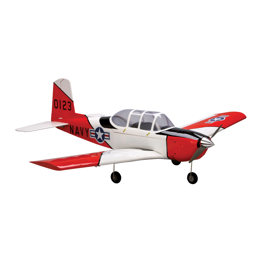
T-34 Mentor 25 ePTS Assembly Manual Specifications Wingspan: 55 in (1575mm) Length: 44 in (1110mm) Wing Area: 545 sq in 34.9 sq dm) Weight w/ Battery: 4.4–4.5 lb (1.9–2.0 kg) Weight w/o Battery: 5.0–5.2 oz (2.2–2.3 kg) -
Page 2: Table Of Contents
Centering the Control Surfaces and This warbird comes ready-to-fly—no building is required and Checking Control Direction ........15 everything needed to fly is included. The T-34 Mentor sports Setting the Control Throws ..........22 removable NACA droops and a progressive 3-position flap General Maintenance ............ -
Page 3: Contents Of Kit/Parts Layout
1- to 3-Cell Li-Po Charger ™ EFLC505 Intelligent 1- to 5-Cell Balancing Charger EFLB32003S 3200mAh 3S 11.1V 20C Li-Po Battery APC12080E 12x8 Elecrtic Prop JSP20050 ST47 Standard Servo SPM6805 Trainer Cord DYN4055 12-Volt, 10-Amp Power Supply E-flite T-34 Mentor ARF Assembly Manual... -
Page 4: Warranty Information
Product. This warranty does not cover damage due to improper installation, operation, maintenance, or attempted repair by anyone other than Horizon. Return of any goods by Purchaser must be approved in writing by Horizon before shipment. E-flite T-34 Mentor ARF Assembly Manual... -
Page 5: Inspection Or Repairs
Product will be repaired or replaced Please call 877-504-0233 with any questions or concerns free of charge. Repair or replacement decisions are at the sole regarding this product or warranty. discretion of Horizon Hobby. E-flite T-34 Mentor ARF Assembly Manual... -
Page 6: Note On Lithium Polymer Batteries
• Keep all chemicals, small parts and anything electrical out of the reach of children. • Moisture causes damage to electronics. Avoid water exposure to all equipment not specifically designed and protected for this purpose. E-flite T-34 Mentor ARF Assembly Manual... -
Page 7: Wing And Landing Gear Assembly
Hint: You can skip steps 1 and 2 if you plan on installing a servo for the operational flaps. Follow the steps in the section "Operational Flap Installation (Optional)" instead. E-flite T-34 Mentor ARF Assembly Manual... - Page 8 5. Attach the landing gear to the bottom of the wing using two landing gear straps, four 3mm x 10mm sheet metal screws and a #2 Phillips screwdriver. Attach both main gears at this time. E-flite T-34 Mentor ARF Assembly Manual...
- Page 9 9. Connect the flap linkage to the flap control horn. We will adjust the flaps to their correct setting later on in the manual in the "Positioning the Flaps" section on page 27. E-flite T-34 Mentor ARF Assembly Manual...
-
Page 10: Tail Installation
Connect the elevator pushrod to the elevator control horn. 3. Slide the rudder partially into the fuselage. Install the control horn so the black screw faces the rear of the fuselage. E-flite T-34 Mentor ARF Assembly Manual... - Page 11 Use threadlock on the screw to prevent it from vibrating loose. 5. Align the control horn so it is 90 degrees to the rudder as shown. E-flite T-34 Mentor ARF Assembly Manual...
- Page 12 8mm sheet metal screws and a #1 Phillips screwdriver. prevent the screw from vibrating loose. 8. Screw the nylon control horn in 1/4-inch (6mm). Connect the clevis from the rudder pushrod to the rudder control horn. E-flite T-34 Mentor ARF Assembly Manual...
-
Page 13: Battery And Wing Installation
1. Remove the canopy from the fuselage by grasping the canopy at the aft edge and rocking it left to right. This will disengage the magnets that hold it in place. The front has two pins that key into the fuselage. E-flite T-34 Mentor ARF Assembly Manual... - Page 14 You will want to make sure you have the wires pressed down flat and to the side of the receiver before installing the top hatch. 4. Use two nylon wing bolts and a flat screwdriver to secure the wing to the fuselage. E-flite T-34 Mentor ARF Assembly Manual...
-
Page 15: Centering The Control Surfaces And Checking Control Direction
If a flight control moves in the incorrect direction we will instruct you how to change it in the next section. , 1. Follow the radio instructions to install the four AA batteries. E-flite T-34 Mentor ARF Assembly Manual... - Page 16 A spinning propeller can cause serious damage or injury. It is always best to stay behind the propeller and keep it away from loose objects when the battery and speed control are connected. E-flite T-34 Mentor ARF Assembly Manual...
- Page 17 Checking the Elevator 5. Center the elevator stick and trim. Thread the clevis in or out on the elevator pushrod until the elevator is aligned with the stabilizer as shown. E-flite T-34 Mentor ARF Assembly Manual...
- Page 18 8. Center the rudder stick and trim. Thread the clevis in make the airplane elevator move down. or out on the rudder pushrod until the rudder is aligned with the fin as shown. E-flite T-34 Mentor ARF Assembly Manual...
- Page 19 transmitter. When the rudder/throttle stick (left side of the transmitter. When the left stick is moved left, the transmitter) is moved right, the rudder should also move rudder should also move left. right. E-flite T-34 Mentor ARF Assembly Manual...
- Page 20 11. Center the aileron stick and trim. Thread the clevis right, the right aileron will move up and the left aileron in or out on the aileron pushrod until the ailerons are will move down. aligned with the wing as shown. E-flite T-34 Mentor ARF Assembly Manual...
- Page 21 (example shown below), you will need to use the Servo move down. Reversing feature of your radio system. Follow the instructions for the radio to enter the programming and change the servo reversing of the offending control surface. E-flite T-34 Mentor ARF Assembly Manual...
-
Page 22: Setting The Control Throws
A spinning propeller can cause serious damage or injury. It is always best to stay behind the propeller and keep it away from loose objects when the battery and speed control are connected. E-flite T-34 Mentor ARF Assembly Manual... - Page 23 High Rate: 3/4-inch (19mm) (Right/Left) 3/4-inch (19mm) 3/8-inch (9.5mm) Low Rate High and Low Rate 3/8-inch (9.5mm) Low Rate 3/4-inch (19mm) High and Low Rate High Rate: 3/4-inch (19mm) (Up/Down) 3/4-inch (19mm) High Rate 3/4-inch (19mm) High Rate E-flite T-34 Mentor ARF Assembly Manual...
- Page 24 Low Rate: 1/4-inch (6mm) (Up/Down) 1/4-inch (6mm) Low Rate 1/4-inch (6mm) Low Rate High Rate: 1/2-inch (13mm) (Up/Down) 1/2-inch (13mm) High Rate 1/2-inch (13mm) High Rate E-flite T-34 Mentor ARF Assembly Manual...
-
Page 25: General Maintenance
3. To check that the motor is secure to the firewall, you will first need to remove the spinner. Use a 2.5mm hex wrench to remove the four screws that secure the cowling to the fuselage. E-flite T-34 Mentor ARF Assembly Manual... - Page 26 Do not use the radio trim install the cowling, propeller and spinner. for ground tracking. The rudder trim at the radio is only used to trim the rudder in flight. E-flite T-34 Mentor ARF Assembly Manual...
-
Page 27: Positioning The Flaps
The setting for the flaps in this position is 1/2-inch (13mm) when measured from the trailing edge of the wing to the trailing edge of the flap. E-flite T-34 Mentor ARF Assembly Manual... -
Page 28: Removing The Naca Wing Droops
1. Carefully remove the tape from the wing on both the like a sport aircraft and will require the greatest amount top and bottom of the wing droop. of skill (for this type of aircraft) during landing. E-flite T-34 Mentor ARF Assembly Manual... -
Page 29: Operational Flap Installation (Optional)
Note: Check your particular cleaner in an inconspicuous place before applying it to the wing. If your cleaner is not compatible with the covering of your aircraft and damages the covering, it will be in a place that cannot be seen. E-flite T-34 Mentor ARF Assembly Manual... - Page 30 3. Use a pin drill and 1/16-inch (1.5mm) drill bit to drill the four holes in the wing to mount the flap servo. E-flite T-34 Mentor ARF Assembly Manual...
- Page 31 6. Use the radio system to center the flap servo. Install the servo arm so it is perpendicular to the servo. You will want equal throw in both directions from this position to operate the flaps. E-flite T-34 Mentor ARF Assembly Manual...
- Page 32 Connect the clevis to the flap control horn. Check that the flap is aligned with the wing. If not, thread the clevis in or out until the flap is aligned with the wing. E-flite T-34 Mentor ARF Assembly Manual...
- Page 33 Your goal here is to mimic the flap of the manual; Wing and Landing Gear Installation settings from the previous section. beginning on page 7. E-flite T-34 Mentor ARF Assembly Manual...
-
Page 34: Center Of Gravity
After the first flights, the CG position can be adjusted for your personal preference. E-flite T-34 Mentor ARF Assembly Manual... -
Page 35: Preflight
Check all the control horns, servo horns, and clevises to make sure they are secure and in good condition. Replace any items that would be considered questionable. Failure of any of these components in flight would mean the loss of your aircraft. E-flite T-34 Mentor ARF Assembly Manual... - Page 36 For flight maneuvers of loops and rolls are easily accomplished with some, it may be possible to use this setting for your first landing the model in the Advanced Flap Setting mode. approaches. E-flite T-34 Mentor ARF Assembly Manual...
- Page 37 E-flite, Horizon Hobby, Inc., its retailers, and any other representatives, assume absolutely no liability for use of this product or failure to comply with these instructions and precautions.
-
Page 38: 2008 Official Ama National Model Aircraft Safety Code
15 minutes. Once it is safe, remove the battery and check for damage. Dispose of damaged batteries appropriately. E-flite T-34 Mentor ARF Assembly Manual... -
Page 39: Optional Items For Your T-34 Mentor
1. Discharge the battery to a maximum of 2.5V using a slow, safe discharge method. 1. Battery temperature the best indicator for safety. The E-flite Li-Po Battery’s temperature should never drop below 32 degrees 2. Leave battery uncharged and retest after at least 24 hours. - Page 40 Ni-cd, NiMh, Li-Ion, Li-Po, and A123 cells. Ask for part number #THP610 at your local hobby dealer. The E-flite Li-po balancing charger is capable of charging up to 5 cell Li-Po packs. Ask for part number #EFLC505 at your local hobby dealer.
- Page 41 E-flite 32003S battery The Thunder Power Extreme V2 battery is the highest quality, The E-flite battery is a high quality replacement battery that strongest power density battery in its class. This battery requires can use either of the chargers listed in this section. Ask for part the Thunder Power 610 Charger listed in this section.
- Page 42 Only personnel involved with flying the aircraft are allowed at or in front of the flight line. Intentional flying behind the flight line is prohibited. E-flite T-34 Mentor ARF Assembly Manual...
-
Page 43: Building And Flying Notes
Building and Flying Notes E-flite T-34 Mentor ARF Assembly Manual... - Page 44 © 2008 Horizon Hobby, Inc. 4105 Fieldstone Road Champaign, Illinois 61822 (877) 504-0233 horizonhobby.com E-fliteRC.com 12845...