Table of Contents
Advertisement
Quick Links
Advertisement
Table of Contents
Troubleshooting

Related Manuals for Symbol SYMBOL MINISCAN MSXX04


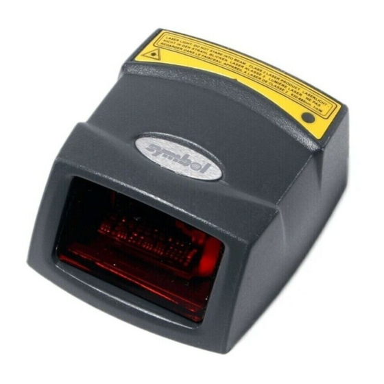
Summary of Contents for Symbol SYMBOL MINISCAN MSXX04
- Page 1 Symbol MiniScan MSXX04 Series Integration Guide...
- Page 3 Symbol MiniScan MSXX04 Series Integration Guide 72E-67134-05 Revision A January 2008...
- Page 4 Motorola. No right to copy a licensed program in whole or in part is granted, except as permitted under copyright law. The user shall not modify, merge, or incorporate any form or portion of a licensed program with other program material, create a derivative work from a licensed program, or use a licensed program in a network without written permission from Motorola.
-
Page 5: Revision History
Revision History Changes to the original manual are listed below: Change Date -01 Rev A 2/2004 Initial release. -02 Rev A 6/2004 Added Embedded Application information. -03 Rev A 8/2006 Software updates. -04 Rev A 3/2007 Updated service information and specifications. -05 Rev A 1/2008 Added new UPC/EAN supplemental options and Bookland ISBN format option,... - Page 6 Symbol MiniScan MSXX04 Series Integration Guide...
-
Page 7: Table Of Contents
Symbol MS3204 Mounting Dimensions ... 2-3 Symbol MS954 Mounting Dimensions ... 2-3 Mounting the Scanner on the Stand ... 2-4 Mounting the Scanner on the Mounting Bracket ... 2-5 Connecting the MiniScan ... 2-7 Location and Positioning ... 2-8 Using the MiniScan as an Embedded Scanner ... 2-8... - Page 8 Symbol MiniScan MSXX04 Series Integration Guide Embedded Applications Requiring a Window ... 2-12 Accessories ... 2-16 Software Developer’s CD ... 2-17 Chapter 3: Scanning Introduction ... 3-1 MiniScan Scan Patterns ... 3-1 Symbol MS1204FZY / MS954 Scan Pattern ... 3-1 Symbol MS2204 and MS2204VHD Scan Patterns ...
- Page 9 Chapter 6: Symbol MS2204VHD Specifications Introduction ... 6-1 Symbol MS2204VHD Electrical Interface ... 6-1 Symbol MS2204VHD Mechanical Drawings ... 6-3 Symbol MS2204VHD Technical Specifications ... 6-5 Symbol MS2204VHD Decode Zones ... 6-8 Symbol MS2204VHD 1D Decode Zone ... 6-8 Symbol MS2204VHD 1D Decode Distances ... 6-9 Symbol MS2204VHD 2D Decode Zone ...
- Page 10 Symbol MiniScan MSXX04 Series Integration Guide Laser On Time ... 10-12 Scan Angle ... 10-12 Power Mode ... 10-13 Trigger Modes ... 10-14 Scanning Mode ... 10-15 Aiming Mode ... 10-16 Programmable Raster Height And Raster Expansion Speed ... 10-17 Timeout Between Decodes ...
- Page 11 Code 39 Check Digit Verification ... 10-53 Transmit Code 39 Check Digit ... 10-53 Enable/Disable Code 39 Full ASCII ... 10-54 Code 39 Decode Performance ... 10-55 Code 39 Decode Performance Level ... 10-56 Code 93 ... 10-57 Enable/Disable Code 93 ... 10-57 Set Lengths for Code 93 ...
- Page 12 Symbol MiniScan MSXX04 Series Integration Guide Data Options ... 10-86 Transmit Code ID Character ... 10-86 Prefix/Suffix Values ... 10-88 Scan Data Transmission Format ... 10-89 Simple Serial Interface (SSI) Options ... 10-91 Baud Rate ... 10-91 Parity ... 10-93 Check Parity ...
- Page 13 Appendix A: ASCII Character Sets RS-232 ASCII Character Set ... A-1 USB ASCII Character Set ... A-6 Glossary Index Tell Us What You Think... Table of Contents...
- Page 14 Symbol MiniScan MSXX04 Series Integration Guide...
-
Page 15: About This Guide
About This Guide Introduction The Symbol MiniScan MSXX04 Series Integration Guide provides general instructions for mounting, setting up, and programming the following Symbol MiniScan models: • MS954 • MS1204FZY • MS2204 • MS2204VHD • MS3204. NOTE It is recommended that an opto-mechanical engineer perform an opto-mechanical analysis prior to integration. -
Page 16: Notational Conventions
Symbol MiniScan MSXX04 Series Integration Guide • Chapter 7, Symbol MS3204 MS3204 scanner. • Chapter 8, Symbol MS954 MS954 scanner. • Chapter 9, Maintenance and MiniScan scanners. • Chapter 10, Parameter Menus programming, and hexadecimal equivalents for host download programming. -
Page 17: Related Documents
Software type and version number. Motorola responds to calls by E-mail, telephone or fax within the time limits set forth in support agreements. If your problem cannot be solved by Motorola Enterprise Mobility Support, you may need to return your equipment for servicing and will be given specific directions. - Page 18 Symbol MiniScan MSXX04 Series Integration Guide...
-
Page 19: Chapter 1 Getting Started
OEM devices for embedded applications such as medical instruments, diagnostic equipment, vending machines, and gaming. As a fixed-mount scanner, the MS1204FZY is ideal for applications requiring unattended scanning such as manufacturing, warehouse and shipping, conveyor belts, library and document tracking systems. -
Page 20: Symbol Ms1204Fzy, Ms2204, Ms2204Vhd, And Ms3204 Features
ATMs, listening stations, lottery machines, and vending machines. • Symbol MS954 scanner is extremely compact, provides easy and flexible integration of bar code scanning into a host device, and offers high-performance scanning on 1D bar codes. The MS954 is ideal for medical instruments and kiosks. -
Page 21: Typical Applications
Typical Applications Symbol MS1204FZY, MS2204, MS2204VHD, and MS3204 Applications Fixed Mount Standalone Applications • Manufacturing / warehouse • Conveyer belts • Security / ID verification • POS. OEM Applications • Kiosks / ATMs • Music listening stations • Security / ID verification •... -
Page 22: Symbol Ms1204Fzy, Ms2204, Ms2204Vhd, And Ms3204 Block Diagram
1 - 4 Symbol MiniScan MSXX04 Series Integration Guide Symbol MS1204FZY, MS2204, MS2204VHD, and MS3204 Block Diagram External Beeper Interface Circuit flex External Trigger Symbol MS1204FZY, MS2204, MS2204VHD, and MS3204 Block Diagram Figure 1-2 Symbol MS954 Block Diagram Interface Board... -
Page 23: Miniscan Block Diagram Descriptions
The MiniScan interface board converts TTL level SSI signals to proper RS-232 levels for connection to any RS-232 compliant host. DB9 - The DB9 connector provides an outlet for the various interface signals used between a MiniScan scanner and the host. It also maintains pin compatibility with the previous generation LS 1220 MiniScan host cables. - Page 24 1 - 6 Symbol MiniScan MSXX04 Series Integration Guide...
-
Page 25: Chapter 2 Installation
This chapter provides information on unpacking, mounting, and installing the MiniScan scanner. Unpacking Remove the MiniScan from its packing and inspect for damage. If the scanner is damaged, call Motorola Enterprise Mobility Support at the telephone number listed on KEEP THE PACKING. It is the approved shipping container and should be used if the equipment needs to be returned for servicing. -
Page 26: Mounting
The following figures provide mounting dimensions for the MiniScan scanner housings. For a mounting template, Chapter 12, Mounting Templates. NOTE Use only non-magnetic M3x.5 screws with a maximum length of 3.6M to mount the MiniScan scanner chassis. Symbol MS1204FZY/MS2204/MS2204VHD Mounting Dimensions... -
Page 27: Symbol Ms3204 Mounting Dimensions
Symbol MS3204 Mounting Dimensions Symbol MS3204 Mounting Dimensions Figure 2-2 Symbol MS954 Mounting Dimensions 2x M3 - 3.6 mm lg. max. Threaded Inserts 2x - 0.080 [2.0] Alignment Holes Note: Dimensions are in inches [mm]. Symbol MS954 Mounting Dimensions Figure 2-3 Threaded Inserts Note: Dimensions are in inches [mm]. -
Page 28: Mounting The Scanner On The Stand
To mount the scanner on the optional stand: Place the bottom of the scanner on the stand’s scanner mount, aligning the scanner’s center threaded insert (beneath the scan window) with the center mounting hole on the front of the stand. The two rear threaded inserts on the bottom of the scanner will align with the proper mounting holes on the stand. -
Page 29: Mounting The Scanner On The Mounting Bracket
Mounting the Stand (optional) You can attach the base of the scanner’s stand to a flat surface using two screws or double-sided tape (not provided). Screw Mount Position the assembled base on a flat surface. Screw one #10 wood screw into each screw-mount hole until the base of the stand is secure. - Page 30 Tilt the scanner bracket in the opposite direction to access the rear scanner mounting holes (which are aligned with the rear inserts on the bottom of the scanner), then insert the remaining two screws provided through the two rear mounting holes and into the scanner’s threaded inserts.
-
Page 31: Connecting The Miniscan
Connecting the MiniScan To connect the MiniScan to the host, connect the scanner cables in the order shown in To Host Beeper (Optional) Trigger or Photo Sensor (Optional) Typical Connection Diagram Figure 2-7 Male jack shown for reference Insertion Direction... -
Page 32: Location And Positioning
NOTE Integrate the scanner in an environment no more extreme than the product’s specification, where the scanner will not exceed its temperature range. For instance, do not mount the scanner onto or next to a large heat source. When placing the scanner with another device, ensure there is proper convection or venting for heat. - Page 33 D = Distance (in inches) from the front edge of the host housing to the bar code. d = The host housing’s internal optical path from the edge of the housing to the front of the MiniScan scanner. B = Internal optical path from the scan mirror to the front edge of the MiniScan scanner.
- Page 34 Check the near and far range on several symbols. If they are not reasonably consistent there may be a printing quality problem that can degrade the performance of the system. Motorola can provide advice on how to improve the installation.
-
Page 35: Conveyor Applications
Conveyor Applications Conveyor applications require setting the conveyor velocity to optimize the scanner’s ability to read symbols. Also consider the orientation of the symbol with respect to the conveyor direction. the relationship of the conveyor velocity with respect to a symbol positioned perpendicular to the conveyor direction... -
Page 36: Embedded Applications Requiring A Window
Use the following guidelines for applications that require a window in front of the MiniScan. NOTE Motorola does not recommend placing an exit window in front of the MiniScan; however, the following information is provided for applications that require such a window. - Page 37 CAUTION Consult an opto-mechanical engineer to recommend an appropriate window material and to determine if coatings are appropriate for the specific application. NOTE Do not use polycarbonate material. Acrylic When fabricated by cell-casting, acrylic has very good optical quality and low initial cost. However, protect the surface from the environment as acrylic is susceptible to attack by chemicals, mechanical stresses, and UV light.
- Page 38 2 - 14 Symbol MiniScan MSXX04 Series Integration Guide Window Coatings Table 2-4 on page 2-14 lists some exit window manufacturers and anti-reflection coaters. Anti-Reflection Coatings Apply an anti-reflection coating to the inside and/or outside of the window to significantly reduce the amount of light reflected off the window, back into the scan engine.
- Page 39 • Optical Working Range - Adding a window can reduce the working range of the scanner since there is a signal loss when passing through window material. To minimize this reduction, use a special coating...
-
Page 40: Accessories
2 - 16 Symbol MiniScan MSXX04 Series Integration Guide Accessories The following accessories are available for the MiniScan scanner, and can be found in Symbol’s Solution Builder (ordering guide). • For power connection • 110V power supply, US, p/n 50-14000-008 •... - Page 41 Simple Serial Interface Software Developer's Kit (SSISDK) The Software Developer's Kit, available from Motorola’s website, provides the software tools required to integrate and communicate with the MiniScan scanners, including: ® • Sample Windows program with source code • DLL with source code for building user applications •...
- Page 42 2 - 18 Symbol MiniScan MSXX04 Series Integration Guide...
-
Page 43: Chapter 3 Scanning
Chapter 3 Scanning Introduction This chapter provides information on scan patterns, scanning, triggering options, and beeper and LED definitions. MiniScan Scan Patterns Symbol MS1204FZY / MS954 Scan Pattern Symbol MS1204FZY and MS954 scanners emit a single scan line to quickly decode 1D bar codes. Single Scan Line Scan Pattern Figure 3-1... -
Page 44: Symbol Ms2204 And Ms2204Vhd Scan Patterns
3 - 2 Symbol MiniScan MSXX04 Series Integration Guide Symbol MS2204 and MS2204VHD Scan Patterns The Symbol MS2204 and MS2204VHD generate different scan patterns (Smart Raster and High Density Single Scan Line) based on the software command received at the interface. The raster pattern can be used to read 1D bar codes and PDF417 symbols. -
Page 45: Symbol Ms3204 Scan Patterns
Symbol MS3204 Scan Patterns The Symbol MS3204 generates four scan patterns based on the software command received at the interface. These patterns are Smart Raster, Semi-omnidirectional, Omnidirectional, and High Density Single Scan Line. The raster pattern can be used to read 1D bar codes and PDF417 symbols. The omnidirectional pattern reads 1D bar codes in an omnidirectional manner. -
Page 46: Scan Angle Selection
High Density Single Scan Line Scan Pattern Figure 3-7 Scan Angle Selection The Symbol MS1204FZY and MS954 scanners support two pre-set scan angles (see each scanner’s technical specifications) Selecting Scan Angle via SSI To use SSI to select the scan angle, issue the SSI PARAM_SEND command with the NUM_SCAN_ANGLE (191) parameter number. -
Page 47: Scanning Tips
Position the scanner closer for symbols with bars that are close together. RIGHT 012345 Position at an Angle Do not position the scanner exactly perpendicular to the bar code. In this position, light can bounce back into the scanner's exit window and prevent a successful decode. Trigger Options Continuous The laser is enabled continuously and decode processing is continuously active. -
Page 48: Level Trigger
When a bar code is presented, the laser remains on until either the bar code is decoded or removed, or the session timeout expires. Once the bar code is decoded, the scanner will not decode it again until the bar code is removed. -
Page 49: Beeper And Led Definitions
If three beeps occur during normal operation, it is due to a reset and any work in progress is lost. If this occurs often, contact Motorola Enterprise Mobility Support. Correct entry scanned or correct menu sequence performed. - Page 50 3 - 8 Symbol MiniScan MSXX04 Series Integration Guide...
-
Page 51: Chapter 4 Symbol Ms1204Fzy Specifications
Chapter 4 Symbol MS1204FZY Specifications Introduction This chapter provides the technical specifications for the Symbol MS1204FZY scanner. Symbol MS1204FZY Electrical Interface MiniScan Connector Figure 4-1... - Page 52 4 - 2 Symbol MiniScan MSXX04 Series Integration Guide lists the pin functions of the Symbol MS1204FZY interface. Table 4-1 Symbol MS1204FZY Electrical Interface Table 4-1 Pin No. Pin Name Trigger Not used Ground Power Beeper/Download *I = Input O = Output Type* Signals scanner to begin scanning session.
-
Page 53: Symbol Ms1204Fzy Mechanical Drawings
Symbol MS1204FZY Mechanical Drawings Notes: Unless otherwise specified: • Dimensions are in inches, dimensions in [ ] are mm. • User mounting tolerances are not included. Symbol MS1204FZY Mechanical Drawing Figure 4-2 Symbol MS1204FZY Specifications 4 - 3... - Page 54 4 - 4 Symbol MiniScan MSXX04 Series Integration Guide Notes: Unless otherwise specified: • Dimensions are in inches, dimensions in [ ] are mm. • User mounting tolerances are not included. Symbol MS1204FZY Mechanical Drawing Figure 4-3...
-
Page 55: Symbol Ms1204Fzy Technical Specifications
8,000 ft. candles (86,112 lux) 450 ft. candles (4,844 lux) Multiple 30” drops Unpowered scanner withstands a random vibration along each of the X, Y and Z axes for a period of one hour per axis, defined as follows: 20 to 80 Hz Ramp up to 0.04 G^2/Hz at the rate of 3dB/octave. - Page 56 4 - 6 Symbol MiniScan MSXX04 Series Integration Guide Symbol MS1204FZY Technical Specifications @ 23°C (Continued) Table 4-2 Item Laser Class Height Width Depth Weight Note: Environmental and/or tolerance parameters are not cumulative. Skew + 50° from normal Skew Angle...
-
Page 57: Symbol Ms1204Fzy Decode Zone
Symbol MS1204FZY Decode Zone The scanner has a selectable scan angle of either 30 figures shown are typical values. angle for selected bar code densities. The minimum element width (or “symbol density”) is the width in mils of the narrowest element (bar or space) in the symbol. The maximum usable length of a symbol at any given range is shown below. -
Page 58: Usable Scan Length
4 - 8 Symbol MiniScan MSXX04 Series Integration Guide Symbol MS1204FZY Decode Distances (42 Table 4-3 Symbol Density/ Bar Code Content/ p/n / Bar Code Type / W-N Ratio 5.0 mil ABCDEFGH 64-17453-01 80% MRD Code 39; 2.5:1 7.5 mil... -
Page 59: Chapter 5 Symbol Ms2204 Specifications
Chapter 5 Symbol MS2204 Specifications Introduction This chapter provides the technical specifications for the Symbol MS2204 scanner. Symbol MS2204 Electrical Interface MiniScan Connector Figure 5-1... - Page 60 5 - 2 Symbol MiniScan MSXX04 Series Integration Guide lists the pin functions of the Symbol MS2204 interface. Table 5-1 Symbol MS2204 Electrical Interface Table 5-1 Pin No. Pin Name Trigger Not used Ground Power Beeper/Download *I = Input O = Output Type* Signals scanner to begin scanning session.
-
Page 61: Symbol Ms2204 Mechanical Drawings
Symbol MS2204 Mechanical Drawings Notes: Unless otherwise specified: • Dimensions are in inches, dimensions in [ ] are mm. • User mounting tolerances are not included. Symbol MS2204 Mechanical Drawing Figure 5-2 Symbol MS2204 Specifications 5 - 3... - Page 62 5 - 4 Symbol MiniScan MSXX04 Series Integration Guide Notes: Unless otherwise specified: • Dimensions are in inches, dimensions in [ ] are mm. • User mounting tolerances are not included. Symbol MS2204 Mechanical Drawing Figure 5-3...
-
Page 63: Symbol Ms2204 Technical Specifications
Symbol MS2204 Technical Specifications Table 5-2 provides the Symbol MS2204 technical specifications Symbol MS2204 Technical Specifications @ 23°C Table 5-2 Item Power Requirements Input Voltage Scanning Current Standby Current Noise Level Laser Power Scan Rate Scan Frequency: Horizontal Scan Frequency: Vertical Frame Rate Print Contrast Scan Angle... - Page 64 Depth Weight Description Unpowered scanner withstands a random vibration along each of the X, Y and Z axes for a period of one hour per axis, defined as follows: 20 to 80 Hz Ramp up to 0.04 G^2/Hz at the rate of 3dB/octave.
- Page 65 Symbol MS2204 Specifications 5 - 7 Skew Pitch + 49° from normal + 55° from normal Pitch Angle Skew Angle Scan Beam Scan Beam Roll + 20° from normal Roll Angle Note: Tolerances are reduced at extreme ends of the working range. Scan Beam Skew, Pitch and Roll Figure 5-4...
-
Page 66: Symbol Ms2204 Decode Zones
5 - 8 Symbol MiniScan MSXX04 Series Integration Guide Symbol MS2204 Decode Zones The decode zone is a function of various symbol characteristics including density, print contrast, wide to narrow ratio and edge acurity. Typical values are shown. and guaranteed distances for selected bar code densities. The minimum element width (or “symbol density”) is the width in mils of the narrowest element (bar or space) in the symbol. -
Page 67: Symbol Ms2204 1D Decode Distances
Symbol MS2204 1D Decode Distances Symbol MS2204 1D Decode Distances Table 5-3 Symbol Density/ Bar Code Content/ p/n / Bar Code Type Contrast 6.0 mil 60-01755-01 80% MRD Code 39 7.5 mil ABCDEF 64-17452-01 80% MRD Code 39 13 mil 012345678905 64-05303-01 80% MRD... -
Page 68: Symbol Ms2204 2D Decode Zone
5 - 10 Symbol MiniScan MSXX04 Series Integration Guide Symbol MS2204 2D Decode Zone Note: Typical performance at 68˚F (20˚C) on high quality symbols in normal room light. Y-module dimension = 3X. Vcc = 5V MS-220X 6.6 mil 10 mil Minimum Element Width, 35% 10 mil Minimum Element Width, 80% 10.1... -
Page 69: Symbol Ms2204 2D Decode Distances
Symbol MS2204 2D Decode Distances Symbol MS2204 2D Slab/Raster Decode Distances Table 5-4 Symbol Density/ Bar Code Content/ p/n / Bar Code Type Contrast 6.6 mil ABCDEF 64-14035-01 80% MRD PDF417 10 mil 012345678905 64-14937-01 35% MRD PDF417 10 mil 80% MRD 64-14037-01 PDF417... - Page 70 5 - 12 Symbol MiniScan MSXX04 Series Integration Guide...
-
Page 71: Chapter 6 Symbol Ms2204Vhd Specifications
Chapter 6 Symbol MS2204VHD Specifications Introduction This chapter provides the technical specifications for the Symbol MS2204VHD scanner. Symbol MS2204VHD Electrical Interface MiniScan Connector Figure 6-1... - Page 72 6 - 2 Symbol MiniScan MSXX04 Series Integration Guide lists the pin functions of the Symbol MS2204VHD. Table 6-1 Symbol MS2204VHD Electrical Interface Table 6-1 Pin No. Pin Name Trigger Not used Ground Power Beeper/Download *I = Input O = Output Type* Signals scanner to begin scanning session.
-
Page 73: Symbol Ms2204Vhd Mechanical Drawings
Symbol MS2204VHD Mechanical Drawings Notes: Unless otherwise specified: • Dimensions are in inches, dimensions in [ ] are mm. • User mounting tolerances are not included. Symbol MS2204VHD Mechanical Drawing Figure 6-2 Symbol MS2204VHD Specifications 6 - 3... - Page 74 6 - 4 Symbol MiniScan MSXX04 Series Integration Guide Notes: Unless otherwise specified: • Dimensions are in inches, dimensions in [ ] are mm. • User mounting tolerances are not included. Symbol MS2204VHD Mechanical Drawing Figure 6-3...
-
Page 75: Symbol Ms2204Vhd Technical Specifications
Symbol MS2204VHD Technical Specifications Table 6-2 provides the Symbol MS2204VHD technical specifications. Symbol MS2204VHD Technical Specifications @ 23°C Table 6-2 Item Power Requirements Input Voltage Scanning Current Standby Current Noise Level Laser Power Scan Rate Scan Frequency: Horizontal Scan Frequency: Vertical Frame Rate Print Contrast Scan Angle... - Page 76 6 - 6 Symbol MiniScan MSXX04 Series Integration Guide Symbol MS2204VHD Technical Specifications @ 23°C (Continued) Table 6-2 Item Vibration Sealing Operating Temperature Storage Temperature Humidity Laser Class Height Width Depth Weight Description Unpowered scanner withstands a random vibration along each of the X, Y...
- Page 77 Symbol MS2204VHD Specifications 6 - 7 Skew Pitch Pitch + 15° from normal + 30° from normal Angle Skew Angle Scan Beam Scan Beam Roll + 4° from normal Roll Angle Note: Tolerances are reduced at extreme ends of the working range. Scan Beam Skew, Pitch and Roll Figure 6-4...
-
Page 78: Symbol Ms2204Vhd Decode Zones
6 - 8 Symbol MiniScan MSXX04 Series Integration Guide Symbol MS2204VHD Decode Zones The decode zone is a function of various symbol characteristics including density, print contrast, wide to narrow ratio and edge acurity. Typical values are shown. and guaranteed distances for selected bar code densities. The minimum element width (or “symbol density”) is the width in mils of the narrowest element (bar or space) in the symbol. -
Page 79: Symbol Ms2204Vhd 1D Decode Distances
Symbol MS2204VHD 1D Decode Distances Symbol MS2204VHD 1D Decode Distances Table 6-3 Symbol Density/ Bar Code Content/ p/n / Bar Code Type Contrast 4 mil STI4026 64-15660-01 80% MRD Code 39 5 mil STI5025 64-18779-01 80% MRD Code 39 6 mil 64-01755-01 80% MRD Code 39... -
Page 80: Symbol Ms2204Vhd 2D Decode Zone
6 - 10 Symbol MiniScan MSXX04 Series Integration Guide Symbol MS2204VHD 2D Decode Zone Note: Typical performance at 68˚F (20˚C) on high quality symbols in normal room light. Y-module dimension = 3X. Vcc = 5V MS-2204VHD 4.0 mil 1.90 1.50... -
Page 81: Symbol Ms2204Vhd 2D Decode Distances
Symbol MS2204VHD 2D Decode Distances Symbol MS2204VHD 2D Slab/Raster Decode Distances Table 6-4 Symbol Density/ Bar Code Content/ p/n / Bar Code Type Contrast 4 mil 64-17025-01 80% MRD PDF417 6.6 mil ABCDEF 64-14035-01 80% MRD PDF417 10 mil 012345678905 64-14937-01 80% MRD PDF417... - Page 82 6 - 12 Symbol MiniScan MSXX04 Series Integration Guide...
-
Page 83: Chapter 7 Symbol Ms3204 Specifications
Chapter 7 Symbol MS3204 Specifications Introduction This chapter provides the technical specifications for the Symbol MS3204 scanner. -
Page 84: Symbol Ms3204 Electrical Interface
7 - 2 Symbol MiniScan MSXX04 Series Integration Guide Symbol MS3204 Electrical Interface This section describes the pin functions of the Symbol MS3204 scanner. Symbol MS3204 Connector Figure 7-1 Symbol MS3204 Electrical Interface Table 7-1 Pin No. Pin Name Trigger... -
Page 85: Symbol Ms3204 Mechanical Drawings
Symbol MS3204 Mechanical Drawings Notes: Unless otherwise specified: • Dimensions are in inches, dimensions in [ ] are mm. • User mounting tolerances are not included. Symbol MS3204 Mechanical Drawing Figure 7-2 Symbol MS3204 Specifications 7 - 3... - Page 86 7 - 4 Symbol MiniScan MSXX04 Series Integration Guide Notes: Unless otherwise specified: • Dimensions are in inches, dimensions in [ ] are mm. • User mounting tolerances are not included. Symbol MS3204 Mechanical Drawing Figure 7-3...
-
Page 87: Symbol Ms3204 Technical Specifications
Symbol MS3204 Technical Specifications Symbol MS3204 Technical Specifications @ 23°C Table 7-2 Item Power Requirements Input Voltage Scanning Current Standby Current Noise Level Laser Power Scan Rate Scan Frequency: Horizontal Scan Frequency: Vertical Frame Rate Print Contrast Scan Angle Scan Pattern Start Time Skew Tolerance Pitch Angle... - Page 88 7 - 6 Symbol MiniScan MSXX04 Series Integration Guide Symbol MS3204 Technical Specifications @ 23°C (Continued) Table 7-2 Item Ambient Light Immunity Sunlight Artificial Light Drop Vibration Sealing Operating Temperature Storage Temperature Humidity Laser Class Height Width Depth Weight Description 8,000 ft.
- Page 89 Symbol MS3204 Specifications 7 - 7 Skew Pitch Pitch + 15° from normal + 30° from normal Angle Skew Angle Scan Beam Scan Beam Roll +4° from normal Roll Angle Note: Tolerances are reduced at extreme ends of the working range. Scan Beam Skew, Pitch and Roll Figure 7-4...
-
Page 90: Symbol Ms3204 Decode Zones
7 - 8 Symbol MiniScan MSXX04 Series Integration Guide Symbol MS3204 Decode Zones The decode zone is a function of various symbol characteristics including density, print contrast, wide to narrow ratio and edge acuity. The figures shown are typical values. - Page 91 3. Working range specifications: Photographic quality symbols, pitch = 15°, skew = 0°, roll = 0°, ambient light < 150 ft. candles, and temperature = 23 °C, Vcc = 5V. 4. Measured from the front of the scanner. Symbol MS3204 Specifications...
-
Page 92: Slab/Raster Decode Distances (Symbol Ms3204-I000 Only)
7 - 10 Symbol MiniScan MSXX04 Series Integration Guide 2D Slab/Raster Decode Distances (Symbol MS3204-I000 Only) Note: Typical performance at 68 on high quality symbols in normal room light. Vcc = 5V 6.6 mil PDF 417 5.25 10 mil PDF 417 15 mil PDF 417 12.7... -
Page 93: Usable Scan Length
3. Working range specifications: Photographic quality symbols, pitch = 15°, skew = 0°, roll = 0°, ambient light < 150 ft. candles, and temperature = 23 °C, Vcc = 5V. 4. Measured from the front of the scanner. Usable Scan Length The decode zone is a function of various symbol characteristics including density, print contrast, wide-to-narrow ratio, and edge acuity. - Page 94 7 - 12 Symbol MiniScan MSXX04 Series Integration Guide...
-
Page 95: Chapter 8 Symbol Ms954 Specifications
Chapter 8 Symbol MS954 Specifications Introduction This chapter provides the technical specifications for the Symbol MS954 scanner. -
Page 96: Symbol Ms954 Electrical Interface
8 - 2 Symbol MiniScan MSXX04 Series Integration Guide Symbol MS954 Electrical Interface MiniScan Connector Figure 8-1 lists the pin functions of the Symbol MS954 interface. Table 8-1 Symbol MS954 Electrical Interface Table 8-1 Pin No. Pin Name Trigger Not used... -
Page 97: Symbol Ms954 Mechanical Drawings
Symbol MS954 Mechanical Drawings Notes: Unless otherwise specified: • Dimensions are in inches, dimensions in [ ] are mm. • User mounting tolerances are not included. Symbol MS954 Mechanical Drawing Figure 8-2 Symbol MS954 Specifications 8 - 3... - Page 98 8 - 4 Symbol MiniScan MSXX04 Series Integration Guide Notes: Unless otherwise specified: • Dimensions are in inches, dimensions in [ ] are mm. • User mounting tolerances are not included. Symbol MS954 Mechanical Drawing Figure 8-3...
-
Page 99: Symbol Ms954 Technical Specifications
Symbol MS954 Technical Specifications Symbol MS954 Technical Specifications @ 23°C Table 8-2 Item Power Requirements Input Voltage Scanning Current Standby Current Noise Level Laser Power Scan Rate Print Contrast Scan Angle Scan Pattern Skew Tolerance Pitch Angle Roll Decode Depth of Field Ambient Light Immunity Sunlight Artificial Light... - Page 100 8 - 6 Symbol MiniScan MSXX04 Series Integration Guide Symbol MS954 Technical Specifications @ 23°C (Continued) Table 8-2 Item Laser Class Height Width Depth Weight Skew + 50° from normal Skew Angle Scan Beam Skew, Pitch and Roll Figure 8-4...
-
Page 101: Symbol Ms954 Decode Zone
Symbol MS954 Decode Zone The decode zone for the Symbol MS954 scanner is shown in Table 8-3 lists the typical and guaranteed distances for selected bar code densities. The minimum element width (or “symbol density”) is the width in mils of the narrowest element (bar or space) in the symbol. To calculate this... -
Page 102: Usable Scan Length
8 - 8 Symbol MiniScan MSXX04 Series Integration Guide Symbol MS954 Decode Distances Table 8-3 Symbol Density/ Bar Code Content/ p/n / Bar Code Type/ W-N Ratio 5 mil ABCDEFGH 64-17453-01 90% MRD Code 39; 2.5:1 7.5 mil ABCDEF 64-17452-01 90% MRD Code 39;... -
Page 103: Chapter 9 Maintenance And Troubleshooting
Chapter 9 Maintenance and Troubleshooting Introduction The chapter provides information on maintenance and troubleshooting. Maintenance Cleaning the exit window is the only maintenance required. Do not allow any abrasive material to touch the window. Clean the scan window with a damp cloth and, if necessary, a non-ammonia based detergent. -
Page 104: Troubleshooting
9 - 2 Symbol MiniScan MSXX04 Series Integration Guide Troubleshooting Troubleshooting Table 9-1 Problem No red LED or nothing happens during a scan attempt. Scanner cannot read the bar code. Laser activates, followed by a beep sequence. Possible Cause No power to the scanner. - Page 105 Trigger, Level Trigger, or Pulse Trigger from Options on page NOTE If after performing these checks the symbol still does not scan, contact the distributor or call Motorola Enterprise Mobility Support at the telephone number listed on Maintenance and Troubleshooting...
- Page 106 9 - 4 Symbol MiniScan MSXX04 Series Integration Guide...
-
Page 107: Chapter 10 Parameter Menus
Chapter 10 Parameter Menus Introduction This chapter describes the programmable parameters, and provides bar codes for programming and hexadecimal equivalents for host download programming. Throughout the programming bar code menus, default values are indicated with asterisks ( Low Power Indicates Default (01h) Feature/Option Hex Value... -
Page 108: Operational Parameters
10 - 2 Symbol MiniScan MSXX04 Series Integration Guide Operational Parameters MiniScan scanners are shipped with the default settings shown in are stored in non-volatile memory and are preserved even when the scanner is powered down. There are two ways to change the default values: •... - Page 109 Default Table (Continued) Table 10-1 Parameter Time-out Between Same Symbol Time-out Between Different Symbols Beep After Good Decode Transmit “No Read” Message Parameter Scanning Linear Code Type Security Level Bi-directional Redundancy UPC/EAN UPC-A UPC-E UPC-E1 EAN-8 EAN-13 Bookland EAN UPC/EAN Coupon Code Decode UPC/EAN Supplementals User-Programmable Supplementals Supplemental 1:...
- Page 110 10 - 4 Symbol MiniScan MSXX04 Series Integration Guide Default Table (Continued) Table 10-1 Parameter EAN-8 Zero Extend Bookland ISBN Format UPC/EAN Security Level Linear UPC/EAN Decode UPC Half Block Stitching (MS2204/ MS2204VHD/MS3204 only) Code 128 Code 128 UCC/EAN-128 ISBT 128...
- Page 111 Default Table (Continued) Table 10-1 Parameter Code 93 Code 93 Set Length(s) for Code 93 Code 11 Code 11 Set Length(s) for Code 11 Code 11 Check Digit Verification Transmit Code 11 Check Digits Interleaved 2 of 5 Interleaved 2 of 5 Set Length(s) for I 2 of 5 I 2 of 5 Check Digit Verification Transmit I 2 of 5 Check Digit...
- Page 112 10 - 6 Symbol MiniScan MSXX04 Series Integration Guide Default Table (Continued) Table 10-1 Parameter MSI Plessey Check Digits Transmit MSI Plessey Check Digit MSI Plessey Check Digit Algorithm PDF417/MicroPDF417 (MS2204, MS2204VHD, and MS3204 only) PDF417 MicroPDF417 MicroPDF Performance Code 128 Emulation...
- Page 113 Default Table (Continued) Table 10-1 Parameter Host RTS Line State Decode Data Packet Format Stop Bit Select Intercharacter Delay Host Serial Response Time-out Host Character Time-out Event Reporting Decode Event Boot Up Event Parameter Event Macro PDF (MS2204, MS2204VHD, and MS3204 only) Transmit Each Symbol in Codeword Format Transmit Unknown Codewords...
-
Page 114: Set Default Parameter
10 - 8 Symbol MiniScan MSXX04 Series Integration Guide Set Default Parameter Set Defaults - Symbol MS1204, MS1204VHD, MS3204 Scan this bar code to return all parameters to the values listed in Table 10-1 on page 10-2. NOTE See Set Defaults - Symbol MS954 on page 10-9 for the Symbol MS954 default parameters. -
Page 115: Set Defaults - Symbol Ms954
Changes to the factory default values can be stored as custom defaults. These values are also stored in non-volatile memory and are preserved even when the scanner is powered down. •... -
Page 116: Scanning Options
10 - 10 Symbol MiniScan MSXX04 Series Integration Guide Scanning Options Beeper Volume Parameter # 8Ch To select a decode beep volume, scan the Low Volume, Medium Volume, or High Volume bar code. Low Volume Medium Volume *High Volume... -
Page 117: Beeper Tone
Beeper Tone Parameter # 91h To select a decode beep frequency (tone), scan the appropriate bar code. Beeper Frequency Adjustment Parameter # F0h 91H This parameter adjusts the frequency of the high beeper tone from the nominal 2500 Hz to another frequency matching the resonances of the installation. -
Page 118: Laser On Time
10 - 12 Symbol MiniScan MSXX04 Series Integration Guide Laser On Time Parameter # 88h This parameter sets the maximum time decode processing continues during a scan attempt. It is programmable in 0.1 second increments from 0.5 to 9.9 seconds. -
Page 119: Power Mode
This parameter determines whether or not power remains on after a decode attempt. In Low Power mode, the scanner enters into a low power consumption mode when possible, provided all WAKEUP signals are released. In Continuous On mode, power remains on after each decode attempt. -
Page 120: Trigger Modes
Blink - This trigger mode is used for triggerless ScanStand operation. Scanning range is reduced in this mode. This mode is only supported by Symbol MS1204FZY and MS954. • Host - A host command issues the triggering signal. The scanner interprets an actual trigger pull as a Level triggering option. *Level... -
Page 121: Scanning Mode
Scanning Mode Parameter # 8Dh NOTE This option is supported by the Symbol MS2204, MS2204VHD and MS3204 only. Select one of the following scanning modes: • Smart Raster•Always Raster • Slab Only Raster•Programmable Raster • Omnidirectional (Cyclone)•Semi-Omnidirectional NOTE If Omnidirectional is selected, disabling the following parameters is recommended: PDF417, MicroPDF417, DataBar Limited, CC-C, CC-AB, TLC-39 and Linear UPC. -
Page 122: Aiming Mode
10 - 16 Symbol MiniScan MSXX04 Series Integration Guide Aiming Mode Parameter # F0h 7Eh NOTE This option is supported by the Symbol MS1204FZY, MS2204, MS2204VHD and MS3204 only. For handheld mode only, select an aiming dot to appear for a normal or extended period of time. -
Page 123: Programmable Raster Height And Raster Expansion Speed
Programmable Raster Height And Raster Expansion Speed Parameter # E4h, E5h NOTE This option is supported by the Symbol MS2204, MS2204VHD and MS3204-I000 only. This parameter selects the laser pattern’s height and rate of expansion, and is only used when Programmable Raster or Always Raster is enabled. -
Page 124: Timeout Between Decodes
When in Continuous triggering mode, this parameter sets the minimum duration of not decoding data before the scanner decodes a second bar code identical to one just decoded. This reduces the risk of accidently scanning the same symbol twice. It is programmable in 0.1 second increments from 0.0 to 9.9 seconds. The recommended interval is 0.6 seconds. -
Page 125: Beep After Good Decode
Parameter # 38h Scan this symbol to set the scanner to beep after a good decode. Scan this symbol to set the scanner not to beep after a good decode. The beeper still operates during parameter menu scanning and indicates error conditions. -
Page 126: Transmit "No Read" Message
10 - 20 Symbol MiniScan MSXX04 Series Integration Guide Transmit “No Read” Message Parameter # 5Eh Enable this option to transmit “NR” if a symbol does not decode. Any enabled prefix or suffixes are appended around this message. When the parameter is disabled, and a symbol can not be decoded, no message is sent to the host. -
Page 127: Parameter Scanning
Parameter Scanning Parameter # ECh To disable the decoding of parameter bar codes, scan the bar code below. The Set Defaults parameter bar code can still be decoded. To enable decoding of parameter bar codes, either scan Set All Defaults or set this parameter to 01h via a serial command. -
Page 128: Linear Code Type Security Level
NOTE Does not apply to Code 128. The MiniScan scanner offer four levels of decode security for linear code types (e.g., Code 39, Interleaved 2 of 5). Select higher security levels for decreasing levels of bar code quality. As security levels increase, the scanner’s aggressiveness decreases. - Page 129 Linear Security Level 3 Code types other than the following must be successfully read twice before being decoded. The following codes must be read three times: Code Type MSI Plessey 4 or less D 2 of 5 8 or less I 2 of 5 8 or less Linear Security Level 4...
-
Page 130: Bi-Directional Redundancy
10 - 24 Symbol MiniScan MSXX04 Series Integration Guide Bi-directional Redundancy Parameter # 43h This parameter is only valid when a parameter is enabled, a bar code must be successfully scanned in both directions (forward and reverse) before being decoded. -
Page 131: Upc/Ean
UPC/EAN Enable/Disable UPC-A Parameter # 01h To enable or disable UPC-A, scan the appropriate bar code below. Enable/Disable UPC-E Parameter # 02h To enable or disable UPC-E, scan the appropriate bar code below. *Enable UPC-A (01h) Disable UPC-A (00h) *Enable UPC-E (01h) Disable UPC-E (00h) -
Page 132: Enable/Disable Upc-E1
10 - 26 Symbol MiniScan MSXX04 Series Integration Guide Enable/Disable UPC-E1 Parameter # 0Ch To enable or disable UPC-E1, scan the appropriate bar code below. Enable UPC-E1 (01h) *Disable UPC-E1 (00h) -
Page 133: Enable/Disable Ean-8
Enable/Disable EAN-8 Parameter # 04h To enable or disable EAN-8, scan the appropriate bar code below. Enable/Disable EAN-13 Parameter # 03h To enable or disable EAN-13, scan the appropriate bar code below. *Enable EAN-8 (01h) Disable EAN-8 (00h) *Enable EAN-13 (01h) Disable EAN-13 (00h) -
Page 134: Enable/Disable Bookland Ean
10 - 28 Symbol MiniScan MSXX04 Series Integration Guide Enable/Disable Bookland EAN Parameter # 53h To enable or disable EAN Bookland, scan the appropriate bar code below. NOTE If you enable Bookland EAN, select a UPC/EAN Supplementals, Autodiscriminate UPC/EAN Supplementals, or Enable 978/979 Supplemental... -
Page 135: Upc/Ean Coupon Code
UPC/EAN Coupon Code Parameter # 55h When enabled, this parameter decodes UPC-A bar codes starting with digit ‘5’, EAN-13 bar codes starting with digit ‘99’, and UPC-A/EAN-128 Coupon Codes. UPC-A, EAN-13 and EAN-128 must be enabled to scan all types of Coupon Codes. NOTE Use the Decode UPC/EAN Supplemental Redundancy parameter to control autodiscrimination of the EAN-128 (right half) of a coupon code. -
Page 136: Decode Upc/Ean Supplementals
Supplementals are bar codes appended according to specific format conventions (e.g., UPC A+2, UPC E+2, EAN 13+2). The following options are available: • If you select Ignore UPC/EAN with Supplementals, and the scanner is presented with a UPC/EAN plus supplemental symbol, the scanner decodes UPC/EAN and ignores the supplemental characters. •... - Page 137 Decode UPC/EAN Supplementals (continued) Select the desired option by scanning one of the following bar codes. Decode UPC/EAN With Supplementals (01h) *Ignore UPC/EAN Supplementals (00h) Autodiscriminate UPC/EAN Supplementals (02h) Enable 378/379 Supplemental Mode (04h) Enable 978/979 Supplemental Mode (05h) Parameter Menus 10 - 31...
- Page 138 10 - 32 Symbol MiniScan MSXX04 Series Integration Guide Decode UPC/EAN Supplementals (continued) Enable 977 Supplemental Mode (07h) Enable 414/419/434/439 Supplemental Mode (06h) Enable 491 Supplemental Mode (08h) Enable Smart Supplemental Mode (03h)
- Page 139 Parameter Menus 10 - 33 Decode UPC/EAN Supplementals (continued) Supplemental User-Programmable Type 1 (09h) Supplemental User-Programmable Type 1 and 2 (0Ah) Smart Supplemental Plus User-Programmable 1 (0Bh) Smart Supplemental Plus User-Programmable 1 and 2 (0Ch)
-
Page 140: User-Programmable Supplementals
10 - 34 Symbol MiniScan MSXX04 Series Integration Guide User-Programmable Supplementals Supplemental 1: Parameter # F1h 43h Supplemental 2: Parameter # F1h 44h If you selected a Supplemental User-Programmable option from select User-Programmable Supplemental 1 to set the 3-digit prefix. Then select the 3 digits using the numeric bar codes beginning on page 10-111. -
Page 141: Transmit Upc-A Check Digit
Transmit UPC-A Check Digit Parameter # 28h Scan the appropriate bar code below to transmit the symbol with or without the UPC-A check digit. Transmit UPC-E Check Digit Parameter # 29h Scan the appropriate bar code below to transmit the symbol with or without the UPC-E check digit. *Transmit UPC-A Check Digit (01h) Do Not Transmit UPC-A Check Digit... -
Page 142: Transmit Upc-E1 Check Digit
10 - 36 Symbol MiniScan MSXX04 Series Integration Guide Transmit UPC-E1 Check Digit Parameter # 2Ah Scan the appropriate bar code below to transmit the symbol with or without the UPC-E1 check digit. *Transmit UPC-E1 CHECK DIGIT (01h) Do Not Transmit UPC-E1 Check Digit... -
Page 143: Upc-A Preamble
UPC-A Preamble Parameter # 22h Preamble characters (Country Code and System Character) can be transmitted as part of a UPC-A symbol. Select one of the following options for transmitting UPC-A preamble to the host device: transmit system character only, transmit system character and country code (“0” for USA), or transmit no preamble. (<... -
Page 144: Upc-E Preamble
10 - 38 Symbol MiniScan MSXX04 Series Integration Guide UPC-E Preamble Parameter # 23h Preamble characters (Country Code and System Character) can be transmitted as part of a UPC-E symbol. Select one of the following options for transmitting UPC-E preamble to the host device: transmit system character only, transmit system character and country code (“0”... -
Page 145: Upc-E1 Preamble
UPC-E1 Preamble Parameter # 24h Preamble characters (Country Code and System Character) can be transmitted as part of a UPC-E1 symbol. Select one of the following options for transmitting UPC-E1 preamble to the host device: transmit system character only, transmit system character and country code (“0” for USA), or transmit no preamble. (<... -
Page 146: Convert Upc-E To Upc-A
10 - 40 Symbol MiniScan MSXX04 Series Integration Guide Convert UPC-E to UPC-A Parameter # 25h This parameter converts UPC-E (zero suppressed) decoded data to UPC-A format before transmission. After conversion, data follows UPC-A format and is affected by UPC-A programming selections (e.g., Preamble, Check Digit). -
Page 147: Convert Upc-E1 To Upc-A
Convert UPC-E1 to UPC-A Parameter # 26h Enable this parameter to convert UPC-E1 (zero suppressed) decoded data to UPC-A format before transmission. After conversion, data follows UPC-A format and is affected by UPC-A programming selections (e.g., Preamble, Check Digit). Scan DO NOT CONVERT UPC-E TO UPC-A to transmit UPC-E1 (zero suppressed) decoded data. EAN Zero Extend Parameter # 27h When this parameter is enabled, five leading zeros are added to decoded EAN-8 symbols to make them... -
Page 148: Bookland Isbn Format
Bookland in this mode. • Bookland ISBN-13 - The scanner reports Bookland data (starting with either 978 or 979) as EAN-13 in 13-digit format to meet the 2007 ISBN-13 protocol. NOTE For Bookland EAN to function properly, first enable Bookland EAN using... -
Page 149: Upc/Ean Security Level
Selecting this level of security significantly impairs the decoding ability of the scanner. If this level of security is necessary, try to improve the quality of the bar codes. -
Page 150: Linear Upc/Ean Decode
10 - 44 Symbol MiniScan MSXX04 Series Integration Guide Linear UPC/EAN Decode Parameter # 44h This option applies to code types containing two adjacent blocks (e.g., UPC-A, EAN-8, EAN-13). When enabled, a bar code is transmitted only when both the left and right blocks are successfully decoded within one laser scan. -
Page 151: Code 128
Code 128 Enable/Disable Code 128 Parameter # 08h To enable or disable Code 128, scan the appropriate bar code below. Enable/Disable UCC/EAN-128 Parameter # 0Eh To enable or disable UCC/EAN-128, scan the appropriate bar code below. *Enable Code 128 (01h) Disable Code 128 (00h) *Enable UCC/EAN-128... -
Page 152: Enable/Disable Isbt 128
10 - 46 Symbol MiniScan MSXX04 Series Integration Guide Enable/Disable ISBT 128 Parameter # 54h To enable or disable ISBT 128, scan the appropriate bar code below. Lengths for Code 128 No length setting is required for Code 128. Enable ISBT 128... -
Page 153: Code 128 Decode Performance
Code 128 Decode Performance Parameter # 48h NOTE This option is supported by the MS2204, MS2204VHD and MS3204 only. This option offers three levels of decode performance or “aggressiveness” for Code 128 symbols. Increasing the performance level reduces the amount of required bar code orientation, which is useful when scanning very long and/or truncated bar codes. -
Page 154: Code 128 Decode Performance Level
10 - 48 Symbol MiniScan MSXX04 Series Integration Guide Code 128 Decode Performance Level Parameter # 49h NOTE This option is supported by the MS2204, MS2204VHD and MS3204 only. Select a level of decode performance. Code 128 Decode Performance Level 1... -
Page 155: Code 39
Code 39 Enable/Disable Code 39 Parameter # 00h To enable or disable Code 39, scan the appropriate bar code below. Enable/Disable Trioptic Code 39 Parameter # 0Dh Trioptic Code 39 is a variant of Code 39 used in marking computer tape cartridges. Trioptic Code 39 symbols always contain six characters. -
Page 156: Convert Code 39 To Code 32
10 - 50 Symbol MiniScan MSXX04 Series Integration Guide Convert Code 39 to Code 32 Parameter # 56h Code 32 is a variant of Code 39 used by the Italian pharmaceutical industry. Scan the appropriate bar code below to enable or disable converting Code 39 to Code 32. -
Page 157: Code 32 Prefix
Code 32 Prefix Parameter # E7h Enable this parameter to add the prefix character “A” to all Code 32 bar codes. be enabled for this parameter to function. NOTE Disable Code 32 Prefix is the default for MS954. Convert Code 39 to Code 32 *Enable Code 32 Prefix (01h) Disable Code 32 Prefix... -
Page 158: Set Lengths For Code 39
10 - 52 Symbol MiniScan MSXX04 Series Integration Guide Set Lengths for Code 39 Parameter # L1 = 12h, L2 = 13h The length of a code refers to the number of characters (i.e., human readable characters), including check digit(s) the code contains. -
Page 159: Code 39 Check Digit Verification
Parameter # 30h When this feature is enabled, the scanner checks the integrity of all Code 39 symbols to verify that the data complies with specified check digit algorithm. Only those Code 39 symbols which include a modulo 43 check digit are decoded. -
Page 160: Enable/Disable Code 39 Full Ascii
10 - 54 Symbol MiniScan MSXX04 Series Integration Guide Enable/Disable Code 39 Full ASCII Parameter # 11h To enable or disable Code 39 Full ASCII, scan the appropriate bar code below. When enabled, the ASCII character set assigns a code to letters, punctuation marks, numerals, and most control keystrokes on the keyboard. -
Page 161: Code 39 Decode Performance
Code 39 Decode Performance Parameter # 46h NOTE This option is supported by the MS2204, MS2204VHD and MS3204 only. This option offers three levels of decode performance or “aggressiveness” for Code 39 symbols. Increasing the performance level reduces the amount of required bar code orientation, which is useful when scanning very long and/or truncated bar codes. -
Page 162: Code 39 Decode Performance Level
10 - 56 Symbol MiniScan MSXX04 Series Integration Guide Code 39 Decode Performance Level Parameter # 47h NOTE This option is supported by the MS2204, MS2204VHD and MS3204 only. Select a level of decode performance. Code 39 Decode Performance Level 1... -
Page 163: Code 93
Code 93 Enable/Disable Code 93 Parameter # 09h To enable or disable Code 93, scan the appropriate bar code below. Enable Code 93 (01h) *Disable Code 93 (00h) Parameter Menus 10 - 57... -
Page 164: Set Lengths For Code 93
10 - 58 Symbol MiniScan MSXX04 Series Integration Guide Set Lengths for Code 93 Parameter # L1 = 1Ah, L2 = 1Bh The length of a code refers to the number of characters (i.e., human readable characters), including check digit(s) the code contains. Lengths for Code 93 can be set for any length, one or two discrete lengths, or lengths within a specific range. -
Page 165: Code 11
Code 11 Enable/Disable Code 11 Parameter # 0Ah To enable or disable Code 11, scan the appropriate bar code below. Enable Code 11 (01h) *Disable Code 11 (00h) Parameter Menus 10 - 59... -
Page 166: Set Lengths For Code 11
10 - 60 Symbol MiniScan MSXX04 Series Integration Guide Set Lengths for Code 11 Parameter # L1 = 1Ch, L2 = 1Dh The length of a code refers to the number of characters (i.e., human readable characters), including check digit(s) the code contains. Lengths for Code 11 can be set for any length, one or two discrete lengths, or lengths within a specific range. -
Page 167: Code 11 Check Digit Verification
Code 11 Check Digit Verification Parameter # 34h When enabled, this parameter checks the integrity of a Code 11 symbol to ensure it complies with a specified check digit algorithm. Select either to check for one check digit, check for two check digits, or to disable the feature. *Disable (00h) One Check Digit... -
Page 168: Transmit Code 11 Check Digit
10 - 62 Symbol MiniScan MSXX04 Series Integration Guide Transmit Code 11 Check Digit Parameter # 2Fh Scan this symbol to transmit the check digit with the data. Scan this symbol to transmit data without the check digit. Transmit Code 11 Check Digit... -
Page 169: Interleaved 2 Of 5
Interleaved 2 of 5 Enable/Disable Interleaved 2 of 5 Parameter # 06h To enable or disable Interleaved 2 of 5, scan the appropriate bar code below. NOTE Enable Interleaved 2 of 5 is the default for MS954. Enable Interleaved 2 of 5 (01h) *Disable Interleaved 2 of 5 (00h) -
Page 170: Set Lengths For Interleaved 2 Of 5
10 - 64 Symbol MiniScan MSXX04 Series Integration Guide Set Lengths for Interleaved 2 of 5 Parameter # L1 = 16h, L2 = 17h The length of a code refers to the number of characters (i.e., human readable characters) the code contains, and includes check digits. -
Page 171: I 2 Of 5 Check Digit Verification
I 2 of 5 Check Digit Verification Parameter # 31h When enabled, this parameter checks the integrity of an I 2 of 5 symbol to ensure it complies with a specified algorithm, either USS (Uniform Symbology Specification), or OPCC (Optical Product Code Council). *Disable (00h) USS Check Digit... -
Page 172: Transmit I 2 Of 5 Check Digit
10 - 66 Symbol MiniScan MSXX04 Series Integration Guide Transmit I 2 of 5 Check Digit Parameter # 2Ch Scan this symbol to transmit the check digit with the data. Scan this symbol to transmit data without the check digit. -
Page 173: Discrete 2 Of 5
Discrete 2 of 5 Enable/Disable Discrete 2 of 5 Parameter # 05h To enable or disable Discrete 2 of 5, scan the appropriate bar code below. Enable Discrete 2 of 5 (01h) *Disable Discrete 2 of 5 (00h) Parameter Menus 10 - 67... -
Page 174: Set Lengths For Discrete 2 Of 5
10 - 68 Symbol MiniScan MSXX04 Series Integration Guide Set Lengths for Discrete 2 of 5 Parameter # L1 = 14h, L2 = 15h The length of a code refers to the number of characters (i.e., human readable characters) the code contains, and includes check digits. -
Page 175: Chinese 2 Of 5
Chinese 2 of 5 Enable/Disable Chinese 2 of 5 Parameter # 0xF0 0x98 To enable or disable Chinese 2 of 5, scan the appropriate bar code below. NOTE Chinese 2 of 5 is supported by the MS954 only. Enable Chinese 2 of 5 (0x01) Disable Chinese 2 of 5 (0x00) -
Page 176: Codabar
10 - 70 Symbol MiniScan MSXX04 Series Integration Guide Codabar Enable/Disable Codabar Parameter # 07h To enable or disable Codabar, scan the appropriate bar code below. Enable Codabar (01h) *Disable Codabar (00h) -
Page 177: Set Lengths For Codabar
Set Lengths for Codabar Parameter # L1 = 18h, L2 = 19h The length of a code refers to the number of characters (i.e., human readable characters) the code contains, including start or stop characters. Lengths for Codabar may be set for any length, one or two discrete lengths, or lengths within a specific range. -
Page 178: Clsi Editing
10 - 72 Symbol MiniScan MSXX04 Series Integration Guide CLSI Editing Parameter # 36h When enabled, this parameter strips the start and stop characters and inserts a space after the first, fifth, and tenth characters of a 14-character Codabar symbol. -
Page 179: Msi Plessey
MSI Plessey Enable/Disable MSI Plessey Parameter # 0Bh To enable or disable MSI Plessey, scan the appropriate bar code below. Enable MSI Plessey (01h) *Disable MSI Plessey (00h) Parameter Menus 10 - 73... -
Page 180: Set Lengths For Msi Plessey
10 - 74 Symbol MiniScan MSXX04 Series Integration Guide Set Lengths for MSI Plessey Parameter # L1 = 1Eh, L2 = 1Fh The length of a code refers to the number of characters (i.e., human readable characters) the code contains, and includes check digits. -
Page 181: Msi Plessey Check Digits
MSI Plessey Check Digits Parameter # 32h These check digits at the end of the bar code verify the integrity of the data. At least one check digit is required. Check digits are not automatically transmitted with the data. If two check digits is selected, also select an Transmit MSI Plessey Check Digit Parameter # 2Eh Scan this symbol to transmit the check digit with the data. -
Page 182: Msi Plessey Check Digit Algorithm
10 - 76 Symbol MiniScan MSXX04 Series Integration Guide MSI Plessey Check Digit Algorithm Parameter # 33h When the Two MSI Plessey check digits option is selected, an additional verification is required to ensure integrity. Select one of the following algorithms. -
Page 183: Pdf417/Micropdf417
PDF417/MicroPDF417 NOTE These options are supported by the MS2204, MS2204VHD and MS3204 only. Enable/Disable PDF417 Parameter # 0Fh To enable or disable PDF417, scan the appropriate bar code below. Enable/Disable MicroPDF417 Parameter # E3h To enable or disable MicroPDF417, scan the appropriate bar code below. Enable PDF417 (01h) Disable PDF417... -
Page 184: Micropdf Performance
10 - 78 Symbol MiniScan MSXX04 Series Integration Guide MicroPDF Performance Parameter # F0h 65h If the scanner is having trouble decoding MicroPDF symbols, select Selective Performance. Note that this can decrease decoding aggressiveness on some symbols. *Standard Performance for MicroPDF... -
Page 185: Code 128 Emulation
Code 128 Emulation Parameter # 7Bh When this parameter is enabled, the scanner transmits data from certain MicroPDF417 symbols as if it was encoded in Code 128 symbols. Transmit AIM Symbology Identifiers must be enabled for this parameter to work. -
Page 186: Gs1 Databar
10 - 80 Symbol MiniScan MSXX04 Series Integration Guide GS1 DataBar GS1 DataBar-14 Parameter # F0h 52h To enable or disable GS1 DataBar-14, scan the appropriate bar code below. GS1 DataBar Limited Parameter # F0h 53h To enable or disable GS1 DataBar Limited, scan the appropriate bar code below. -
Page 187: Gs1 Databar Expanded
GS1 DataBar Expanded Parameter # F0h 54h To enable or disable GS1 DataBar Expanded, scan the appropriate bar code below. Enable GS1 DataBar Expanded (01h) *Disable GS1 DataBar Expanded (00h) Parameter Menus 10 - 81... -
Page 188: Convert Gs1 Databar To Upc/Ean
10 - 82 Symbol MiniScan MSXX04 Series Integration Guide Convert GS1 DataBar to UPC/EAN Parameter # F0h 8Dh NOTE This option is supported by the MS1204FZY only. This parameter only applies to GS1 DataBar-14 and GS1 DataBar Limited symbols not decoded as part of a Composite symbol. -
Page 189: Composite
Composite NOTE These options are supported by the MS2204, MS2204VHD, and MS3204 only. Composite CC-C Parameter # F0h 55h Scan a bar code below to enable or disable Composite bar codes of type CC-C. Enable CC-C (01h) Disable CC-C (00h) Parameter Menus 10 - 83... -
Page 190: Composite Cc-A/B
10 - 84 Symbol MiniScan MSXX04 Series Integration Guide Composite CC-A/B Parameter # F0h 56h Scan a bar code below to enable or disable Composite bar codes of type CC-A/B. Composite TLC-39 Parameter # F0h 73h Scan a bar code below to enable or disable Composite bar codes of type TLC-39. -
Page 191: Upc Composite Mode
If 2D is not present, the UPC bar code does not transmit. • If Autodiscriminate UPC Composites is selected, the scanner determines if there is a 2D portion, then transmits the UPC, as well as the 2D portion if present. -
Page 192: Data Options
10 - 86 Symbol MiniScan MSXX04 Series Integration Guide Data Options Transmit Code ID Character Parameter # 2Dh A code ID character identifies the code type of a scanned bar code. This can be useful when decoding more than one code type. The code ID character is inserted between the prefix character (if selected) and the decoded symbol. - Page 193 Parameter Menus 10 - 87 Transmit Code ID Character (continued) Symbol Code ID Character (02h) AIM Code ID Character (01h) *None (00h)
-
Page 194: Prefix/Suffix Values
10 - 88 Symbol MiniScan MSXX04 Series Integration Guide Prefix/Suffix Values Parameter # P = 69h, S1 = 68h, S2 = 6Ah A prefix and/or one or two suffixes can be appended to scan data for use in data editing. To set a value for a prefix or suffix, scan a four-digit number (i.e., four bar codes;... -
Page 195: Scan Data Transmission Format
Scan Data Transmission Format Parameter # EBh To change the scan data format, scan one of the following eight bar codes corresponding to the desired format. NOTE To set values for the prefix and/or suffix, see Prefix/Suffix Values on page *Data As Is (00h) <DATA>... - Page 196 10 - 90 Symbol MiniScan MSXX04 Series Integration Guide Scan Data Transmission Format (continued) <PREFIX> <DATA> (04h) <PREFIX> <DATA> <SUFFIX 1> (05h) <PREFIX> <DATA> <SUFFIX 2> (06h) <PREFIX> <DATA> <SUFFIX 1> <SUFFIX 2> (07h)
-
Page 197: Simple Serial Interface (Ssi) Options
Parameter # 9Ch Baud rate is the number of bits of data transmitted per second. The scanner's baud rate setting should match the data rate setting of the host device. If not, data may not reach the host device or may reach it in distorted form. - Page 198 10 - 92 Symbol MiniScan MSXX04 Series Integration Guide Baud Rate (continued) Baud Rate 4800 (05h) *Baud Rate 9600 (06h) Baud Rate 19,200 (07h) 38,400 (08h)
-
Page 199: Parity
Parity Parameter # 9Eh A parity check bit is the most significant bit of each ASCII coded character. Select the parity type according to host device requirements. If you select Odd parity, the parity bit has a value 0 or 1, based on data, to ensure that an odd number of 1 bits is contained in the coded character. -
Page 200: Check Parity
10 - 94 Symbol MiniScan MSXX04 Series Integration Guide Check Parity Parameter # 97h NOTE This option is supported by the MS1204FZY, MS2204, MS2204VHD and MS3204 only. Select whether or not to check the parity of received characters. Select the type of parity through the Parity parameter. -
Page 201: Software Handshaking
The scanner waits up to the programmable Host Serial Response Time-out to receive an ACK or NAK. If the scanner does not get a response in this time, it resends its data up to two times before discarding the data and declaring a transmit error. -
Page 202: Host Rts Line State
The SSI Interface is intended to be used with host applications which also implement the SSI protocol. However, the scanner can be used in a "scan-and-transmit" mode to communicate with any standard serial communications software on a host PC (see Decode Data Packet Format on page the host PC may be asserting hardware handshaking lines which interfere with the SSI protocol. -
Page 203: Decode Data Packet Format
Decode Data Packet Format Parameter # EEh This parameter selects whether decoded data is transmitted in raw format (unpacketed), or transmitted with the packet format as defined by the serial protocol. If the raw format is chosen, ACK/NAK handshaking is automatically disabled for decode data. Stop Bit Select Parameter # 9Dh The stop bit(s) at the end of each transmitted character marks the end of transmission of one character and... -
Page 204: Intercharacter Delay
10 - 98 Symbol MiniScan MSXX04 Series Integration Guide Intercharacter Delay Parameter # 6Eh The intercharacter delay gives the host system time to service its receiver and perform other tasks between characters. Select the intercharacter delay option matching host requirements. The delay period can range from no delay to 99 msec in 1 msec increments. -
Page 205: Event Reporting
Number expected Decode Event Parameter # F0h 00h When enabled, the scanner sends a message to the host whenever a bar code is successfully decoded. When disabled, no message is sent. Table 10-3 by scanning the appropriate bar codes on the following pages. Parameter... -
Page 206: Boot Up Event
When enabled, the sends a message a message to the host whenever power is applied. When disabled, no message is sent. Parameter Event Parameter # F0h 03h When enabled, the scanner sends a message to the host when one of the events specified in 10-99 occurs. When disabled, no message is sent. Enable... -
Page 207: Macro Pdf Features
Macro PDF Features NOTE These options are supported by the MS2204, MS2204VHD and MS3204 only. Transmit Symbols in Codeword Format Parameter # Afh Enable this to transmit each PDF symbol as directly decoded data codewords, whether or not that symbol is part of a macro PDF sequence. -
Page 208: Transmit Unknown Codewords
10 - 102Symbol MiniScan MSXX04 Series Integration Guide Transmit Unknown Codewords Parameter # BAh Select Transmit Unknown Codewords to use the output codeword format for transmitting any non-GLI or non-macro PDF codeword. Select Do Not Transmit Unknown Codewords to sound a decode error beep when an unknown codeword is found. -
Page 209: Escape Characters
Escape Characters Parameter # E9h This enables the backslash (\) character as an Escape character for systems that can process transmissions containing special data sequences. Scan a bar code below to either format special data (e.g., GLI escapes, MacroPDF417 Control Block optional fields) according to the GLI (Global Label Identifier) protocol or the ECI (Extended Channel Interpretation) protocol, or to disable this parameter. -
Page 210: Delete Character Set Ecis
10 - 104Symbol MiniScan MSXX04 Series Integration Guide Delete Character Set ECIs Parameter # E6h NOTE This option is supported by the MS2204, MS2204VHD and MS3204 only. Select Delete Character Set ECIs to delete any escape sequences representing Character Set ECIs (also known as GLIs) from its buffer before transmission. -
Page 211: Eci Decoder
ECIs 000900 through 000913, used for efficient encoding of Common Data Syntax Format 00-99. If this parameter is disabled, and a symbol is scanned that was encoded using an ECI escape, the scanner transmits the ECI escape followed by the uninterpreted data. -
Page 212: Transmit Macro Pdf User-Selected Fields
10 - 106Symbol MiniScan MSXX04 Series Integration Guide Transmit Macro PDF User-Selected Fields NOTE These options are supported by the MS2204, MS2204VHD and MS3204 only. Enable or disable each of the following parameters to indicate whether or not to transmit the specified field in subsequently scanned Macro PDF417 symbols. -
Page 213: Transmit Block Count
Transmit Block Count Parameter # B1h Transmit Block Count activates transmission of the block count field. The field character tag is \923\001. For example, the field may be: \923\0011856. Transmit Time Stamp Parameter # B2h Transmit Time Stamp activates transmission of the time stamp field. The field character tag is \923\002. For example, the field may be: \923\0022123443243234. -
Page 214: Transmit Sender
10 - 108Symbol MiniScan MSXX04 Series Integration Guide Transmit Sender Parameter # B3h Transmit Sender activates transmission of the sender field. The field character tag is \923\003. For example, the field may be: \923\003Motorola Holtsville, NY. Transmit Addressee Parameter # B4h Transmit Addressee activates transmission of the addressee field. -
Page 215: Transmit Checksum
Transmit Checksum Parameter # B6h Transmit Checksum activates transmission of the checksum field. The field character tag is \923\006. For example, the field may be: \923\00663823. Transmit File Size Parameter # B5h Transmit File Size activates transmission of the file size field. The field character tag is \923\005. For example, the field may be: \923\005179234. -
Page 216: Transmit Macro Pdf Control Header
10 - 110Symbol MiniScan MSXX04 Series Integration Guide Transmit Macro PDF Control Header Parameter # B7h Transmit Macro PDF Control Header activates transmission of the control header, which contains the segment index and the file ID. For example, the field can be: \92800000\725\120\343. The five digits after the \928 are the segment index (or block index), and \725\120\343 is the file ID. -
Page 217: Numeric Bar Codes
Parameter Menus10 - 111 Numeric Bar Codes For parameters requiring specific numeric values, scan the appropriately numbered bar code(s). - Page 218 10 - 112Symbol MiniScan MSXX04 Series Integration Guide Numeric Bar Codes (continued)
-
Page 219: Cancel
Parameter Menus10 - 113 Cancel To change a selection or cancel an incorrect entry, scan the bar code below. Cancel... - Page 220 10 - 114Symbol MiniScan MSXX04 Series Integration Guide...
-
Page 221: Chapter 11 Simple Serial Interface (Ssi)
Developer’s Guide (p/n 72-50705-xx) provide general information on SSI, include information on the decoder’s hardware signals, and describe the commands. The following SSI information is specific to the MiniScan scanner. NOTE MiniScan scanners only support Multipacketing Option 1. See the SSI Programmer’s Guide for more information. -
Page 222: Ssi Commands Not Supported
11 - 2 Symbol MiniScan MSXX04 Series Integration Guide Table 11-1 lists the codes identifying the MiniScan scanner when using SSI. MiniScan Codes Table 11-1 Code Description MS1204FZY MS2204 MS2204VHD MS3204-I000 MS3204-E000 MS954 SSI Commands Not Supported The following SSI Commands included in the Simple Serial Interface (SSI) Programmer’s Guide are NOT supported by the MiniScan scanner: •... -
Page 223: Chapter 12 Mounting Templates
Chapter 12 Mounting Templates Introduction This chapter provides mounting templates for MiniScan scanners. Copy the page with your MiniScan model’s template to aid in mounting. Symbol MS1204FZY/MS2204/MS2204VHD Mounting Template Symbol MS1204FZY/MS2204/MS2204VHD Mounting Template Figure 12-1... -
Page 224: Symbol Ms3204 Mounting Template
12 - 2 Symbol MiniScan MSXX04 Series Integration Guide Symbol MS3204 Mounting Template Symbol MS3204 Mounting Template Figure 12-2 Symbol MS954 Mounting Template Symbol MS954 Mounting Template Figure 12-3... -
Page 225: Rs-232 Ascii Character Set
Appendix A ASCII Character Sets RS-232 ASCII Character Set The values in Table A-1 can be assigned as prefixes or suffixes for ASCII character data transmission in an RS-232 environment. Prefix/Suffix Values Table A-1 Prefix/Suffix Value Code 39 Encode Character 1000 1001 1002... - Page 226 A - 2 Symbol MiniScan MSXX04 Series Integration Guide Prefix/Suffix Values (Continued) Table A-1 Prefix/Suffix Value Code 39 Encode Character 1016 1017 1018 1019 1020 1021 1022 1023 1024 1025 1026 1027 1028 1029 1030 1031 1032 Space 1033 1034...
- Page 227 Prefix/Suffix Values (Continued) Table A-1 Prefix/Suffix Full ASCII Value Code 39 Encode Character 1045 1046 1047 1048 1049 1050 1051 1052 1053 1054 1055 1056 1057 1058 1059 1060 1061 1062 1063 1064 1065 1066 1067 1068 1069 1070 1071 1072 1073 ASCII Character Sets...
- Page 228 A - 4 Symbol MiniScan MSXX04 Series Integration Guide Prefix/Suffix Values (Continued) Table A-1 Prefix/Suffix Value Code 39 Encode Character 1074 1075 1076 1077 1078 1079 1080 1081 1082 1083 1084 1085 1086 1087 1088 1089 1090 1091 1092 1093...
- Page 229 Prefix/Suffix Values (Continued) Table A-1 Prefix/Suffix Full ASCII Value Code 39 Encode Character 1103 1104 1105 1106 1107 1108 1109 1110 1111 1112 1113 1114 1115 1116 1117 1118 1119 1120 1121 1122 1123 1124 1125 1126 1127 7013 ASCII Character Sets ASCII Character Undefined ENTER...
-
Page 230: Usb Ascii Character Set
A - 6 Symbol MiniScan MSXX04 Series Integration Guide USB ASCII Character Set The values in Table A-2 can be used for ASCII character data transmission in a USB environment. USB ASCII Character Set Table A-2 Prefix/ Suffix Value Code 39 Encode Char. - Page 231 USB ASCII Character Set (Continued) Table A-2 Prefix/ Suffix Full ASCII Value Code 39 Encode Char. 1024 1025 1026 1027 1028 1029 1030 1031 1032 Space 1033 1034 1035 1036 1037 1038 1039 1040 1041 1042 1043 1044 1045 1046 1047 1048 1049...
- Page 232 A - 8 Symbol MiniScan MSXX04 Series Integration Guide USB ASCII Character Set (Continued) Table A-2 Prefix/ Suffix Value Code 39 Encode Char. 1051 1052 1053 1054 1055 1056 1057 1058 1059 1060 1061 1062 1063 1064 1065 1066 1067...
- Page 233 USB ASCII Character Set (Continued) Table A-2 Prefix/ Suffix Full ASCII Value Code 39 Encode Char. 1078 1079 1080 1081 1082 1083 1084 1085 1086 1087 1088 1089 1090 1091 1092 1093 1094 1095 1096 1097 1098 1099 1100 1101 1102 1103 1104...
- Page 234 A - 10 Symbol MiniScan MSXX04 Series Integration Guide USB ASCII Character Set (Continued) Table A-2 Prefix/ Suffix Value Code 39 Encode Char. 1105 1106 1107 1108 1109 1110 1111 1112 1113 1114 1115 1116 1117 1118 1119 1120 1121...
- Page 235 USB ASCII Character Set (Continued) Table A-2 Prefix/ Suffix Full ASCII Value Code 39 Encode Char. 2068 ALT D 2069 ALT E 2070 ALT F 2071 ALT G 2072 ALT H 2073 ALT I 2074 ALT J 2075 ALT K 2076 ALT L 2077...
- Page 236 A - 12 Symbol MiniScan MSXX04 Series Integration Guide USB ASCII Character Set (Continued) Table A-2 Prefix/ Suffix Value Code 39 Encode Char. Other Value Keystroke GUI Shift Keys ™ The Apple iMac keyboard has an apple key on either side of the space bar. Windows-based systems have a GUI key to the left of the left ALT key, and to the right of the right ALT key.
- Page 237 USB ASCII Character Set (Continued) Table A-2 Prefix/ Suffix Full ASCII Value Code 39 Encode Char. 3078 GUI N 3079 GUI O 3080 GUI P 3081 GUI Q 3082 GUI R 3083 GUI S 3084 GUI T 3085 GUI U 3086 GUI V 3087...
- Page 238 A - 14 Symbol MiniScan MSXX04 Series Integration Guide USB ASCII Character Set (Continued) Table A-2 Prefix/ Suffix Value Code 39 Encode Char. 5014 5015 5016 5017 5018 5019 5020 5021 5022 5023 5024 Keypad Keystroke 6042 6043 6044 undefined...
- Page 239 USB ASCII Character Set (Continued) Table A-2 Prefix/ Suffix Full ASCII Value Code 39 Encode Char. 6057 6058 Enter 6059 Num Lock Extended Keypad Keystroke 7001 Break 7002 Delete 7003 PgUp 7004 7005 Pg Dn 7006 Pause 7007 Scroll Lock 7008 Backspace 7009...
- Page 240 A - 16 Symbol MiniScan MSXX04 Series Integration Guide...
- Page 241 Glossary AIM. Automatic Identification Manufacturers, Inc. is the trade association for manufacturers of automatic identification systems. Alphanumeric. A character set that contains letters, numbers and other characters such as special symbols. Aperture. The opening in an optical system defined by a lens or baffle that establishes the field of view. ASCII.
- Page 242 Bi-directional. Denotes that a machine-readable symbol can be read successfully in two directions – either backwards or forwards. Also identifies a scanner that can operate or a bar code that can be read independent of scanning direction. Binary. Denotes a numbering system to base 2 in which numbers are expressed as combinations of the digits 0 and 1 with positional weighting based on powers of 2.
- Page 243 Character Set. Those characters available for encoding in a particular bar code symbology. Check Digit. A digit used to verify a correct symbol decode. The scanner inserts the decoded data into an arithmetic formula and checks that the resulting number matches the encoded check digit. Check digits are required for UPC but are optional for other symbologies.
- Page 244 Decryption. Decryption is the decoding and unscrambling of received encrypted data. Also see, Encryption and Key. Depth of Field. The range between minimum and maximum distances at which a scanner can read a symbol with a certain minimum element width.
- Page 245 U.P.C. is often considered a 12-digit code. The 13th digit of EAN/U.P.C. symbol is a derived character in the left-most position. In the case of U.P.C., this derived left-most character is a 0. Element. Generic term for a bar or space. Encoded Area.
- Page 246 Laser Diode. A gallium-arsenide semiconductor type of laser connected to a power source to generate a laser beam. This laser type is a compact source of coherent light. Laser Scanner. An optical bar code reading device using a coherent laser light beam as its source of illumination. LCD. See Liquid Crystal Display.
- Page 247 Nominal Size. Standard size for a bar code symbol. Most UPC/EAN codes are used over a range of magnifications (e.g., from 0.80 to 2.00 of nominal). Non-Contact Reader/Scanner. Bar code readers requiring no physical contact with the printed symbol. Glossary - 7...
- Page 248 Omnidirectional. Bar codes read in any orientation relative to the scanner. Optical Throw. The distance from the scanner face to the closest point at which symbol can be read; also, optical throw is the difference between range and depth of field.
- Page 249 Scan Area. Area intended to contain a symbol. Scanner. An electronic device used to scan bar code symbols and produce a digitized pattern that corresponds to the bars and spaces of the symbol. Its three main components are: 1) Light source (laser or photoelectric cell) - illuminates a bar code,;...
- Page 250 Glossary - 10 Symbol MiniScan MSXX04 Series Integration Guide Start/Stop Character. A pattern of bars and spaces that provides the scanner with start and stop reading instructions and scanning direction. The start and stop characters are normally to the left and right margins of a horizontal code.
- Page 251 Visible Laser Diode (VLD). A solid state device which produces visible laser light. Wand Scanner. A handheld scanning device used as a contact bar code or OCR reader. Wedge. A device that plugs in between a keyboard and a terminal and allows data to be entered by a keyboard or by various types of scanners.
- Page 252 Glossary - 12 Symbol MiniScan MSXX04 Series Integration Guide...
- Page 253 ......2-5 bullets ........xiv calculating the usable scan length .
- Page 254 ....2-5 mounting scanner on stand ....2-4 mounting stand .
- Page 255 Code 11 ......10-59 check digit verification ....10-61 lengths .
- Page 256 MS954 ....... . . 8-5 scanner pattern ......3-1 scanning modes .
- Page 257 We’d like to know what you think about this Manual. Please take a moment to fill out this questionnaire and fax this form to: (631) 738-4618, or mail to: Motorola, Inc. One Motorola Plaza M/S B-10 Holtsville, NY 11742-1300 Attention: Technical Publications Manager Advanced Data Capture Division IMPORTANT: If you need product support, please call the appropriate customer support number provided.
- Page 260 1-800-927-9626 http://www.symbol.com MOTOROLA and the Stylized M Logo and Symbol and the Symbol logo are registered in the U.S. Patent and Trademark Office. All other product or service names are the property of their respective owners. © Motorola, Inc. 2007...