
SICK S3000 Expert Manuals
Manuals and User Guides for SICK S3000 Expert. We have 8 SICK S3000 Expert manuals available for free PDF download: Operating Instructions Manual, Addendum Operating Instructions, Product Information, Mounting Instructions, Mounting Instruction
Advertisement


Advertisement


SICK S3000 Expert Mounting Instructions (10 pages)
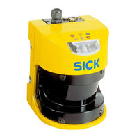
Safety laser scanner

SICK S3000 Expert Mounting Instruction (2 pages)
Heavy Duty Mounting Bracket
Advertisement