Sign In
Upload
Manuals
Brands
SICK Manuals
Scanner
S300 Mini
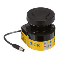
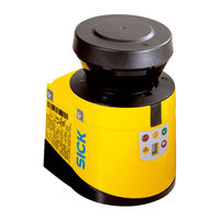
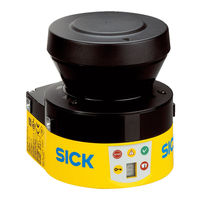
User Manuals: SICK S300 Mini Safety Laser Scanner
Manuals and User Guides for SICK S300 Mini Safety Laser Scanner. We have
7
SICK S300 Mini Safety Laser Scanner manuals available for free PDF download: Operating Instructions Manual, Manual, Mounting Instructions
SICK S300 Mini Operating Instructions Manual (140 pages)
Safety laser scanner
Brand:
SICK
| Category:
Scanner
| Size: 5 MB
Table of Contents
Table of Contents
3
1 About this Document
7
Purpose of this Document
7
Scope
7
Target Groups and Structure of These Operating Instructions
7
Further Information
8
Symbols and Document Conventions
8
2 Safety Information
10
General Safety Notes
10
Intended Use
10
Laser Class 1
10
Inappropriate Use
11
Applications of the Device
11
Requirements for the Qualification of Personnel
11
3 Product Description
13
Construction and Function
13
Principle of Operation of the Safety Laser Scanner Time-Of-Flight Measurement
13
Principle of Operation of the Safety Laser Scanner Rotation
14
Product Characteristics
15
Specific Features
15
Device Overview
15
Functions
16
Scanning Ranges
16
Device Components
16
Status Indicators
17
Protective Field Ranges
17
Status Indicators of the Safety Laser Scanner
17
Protective Field, Warning Field and Field Set
18
Monitoring Cases
19
Field Set with One Protective Field and Two Warning Fields
19
Interoperability
20
S300 Mini Remote with 2 Monitoring Cases on One AGV
20
EFI System with Flexi Soft
21
EFI System with Safety Laser Scanners
21
Interoperability with Safety Laser Scanners
22
S300 Mini, S300 and S3000 in Conjunction with a Flexi Soft Safety Controller
23
Configuration Example in Flexi Soft Designer
23
Example Applications
24
Ardous Area
25
Hazardous Point Protection: Hand Detection
26
Access Protection: Detection of a Person When Accessing a Hazardous Area
27
Mobile Hazardous Area Protection: Detection of a Person When a Vehicle Approaches
28
4 Project Planning
29
Manufacturer of the Machine
29
Operator of the Machine
29
Design
29
If Several Safety Laser Scanners Are Used
31
Prevent Crawling Beneath, Standing Behind, or Climbing over
31
Mounting Opposite
32
Mounting Offset Parallel
32
Mounting Crosswise
32
Mounting Upside Down, Offset Parallel
32
Mounting both Devices Upside Down, Offset Parallel
32
Measures to Prevent Unsecured Areas
33
Mounting One Device Upside Down, Offset Parallel
33
Unsecured Areas
33
Avoid Unsecured Areas
34
Mounting Example for Front and Side Protection in One Direction of Travel
35
Mounting Example for All Round Protection in any Direction of Travel
35
Timing for Monitoring Case Switching
36
Advancing the Switching Time
36
Advancing the Switching Time (Example)
37
Stationary Applications in Horizontal Operation
38
Horizontally Mounted Stationary Application
39
Minimum Distance S
40
Mounting Options for the Scan Plane
41
Advantages and Disadvantages of the Mounting Options
42
Stationary Vertical Operation for Access Protection
43
Relationship between Resolution and Protective Field Mounting Height
43
Access Protection
44
Stationary Vertical Operation for Hazardous Point Protection
45
Minimum Distance to Hazardous Area
46
Mobile Applications
47
Stopping Distance
48
Stopping Distance as a Function of the Vehicle's Speed
49
Supplement Due to Lack of Ground Clearance
50
Vehicle Ground Clearance Graph
50
Fitting Height
51
Integration in Electrical Control
52
Connection Diagrams
52
Connection Diagram for Restart Interlock and External Device Monitoring
53
Schematic Legend for Connection Diagrams
53
Connection Diagram for Restart Interlock and External Device Monitoring in Con- Junction with a UE10 Safety Relay
54
Connection Diagram for S300 Mini Standard on a Flexi Classic Safety Controller.55
55
Connection Diagram for Monitoring Case Switching between Two Safety Laser Scan- Ners Using a Flexi Soft Safety Controller
55
Connection Diagram for Monitoring Case Switching between an S3000 Expert and an S300 Mini Remote Using Static Inputs
56
An S300 Mini Remote Using Static and Dynamic Inputs
57
5 Mounting
58
Safety
58
Mounting Procedure
59
Prevent Crawling Beneath, Standing Behind, or Climbing over
59
Direct Mounting
60
Mounting Using Mounting Kit 1A or 1B
60
Mounting Using Mounting Kits 2 and 3.................................. 5.2.4 Information Label Notes on Daily Check
61
Mounting Using Mounting Kit 1B Including Optics Cover Protection
61
Mounting Using Mounting Kit 2
62
6 Electrical Installation
64
Safety
64
Pin Assignment
65
Round Plug Connector of the S300 Mini Standard
66
Pin Assignment of the S300 Mini Standard
66
Core Assignment of the S300 Mini Standard Extension Cable
66
Round Plug Connector of the S300 Mini Remote
67
Pin Assignment of the S300 Mini Remote
67
M8 × 4 Configuration Connection (Serial Interface)
68
Pin Assignment on the M8 × 4 Configuration Connection
68
Core Assignment of the S300 Mini Remote Extension Cable
68
7 Configuration
69
Delivery State
69
Cds
69
Preparing the Configuration
69
System Parameters
70
Configuration Connection
70
Application Name
71
Name of the Scanner
71
User Data
71
Display Direction of the 7-Segment Display
71
Application
71
Comparison of Mobile and Stationary Applications
71
Resolution
72
Maximum Protective Field Ranges at Different Resolutions
72
Basic Response Time
73
Maximum Protective Field Range
73
Inputs
73
Input Condition Via EFI: Static Information from Inputs of a Flexi Soft
73
Input Condition Via EFI: Speed Information from Encoders on an S3000
73
Input Delay
74
Sampling for the Static Control Inputs
74
Empirical Values for the Required Input Delay
74
Level at the Connections for the Control Inputs for Complementary Sampling
74
Truth Table for 1-Of-N Sampling with Two Input Pairs
74
Ossds
75
External Device Monitoring (EDM)
75
Restart
76
Behavior of the Device on a Contactor Malfunction
76
Schematic Representation of Operation with Restart Interlock
77
Universal I/O Connections
78
Field Sets
80
Configuring the Protective Field and Warning Field
80
Dard
80
Creating a Field Set in the CDS
80
Number of Field Sets that Can be Configured Per Variant
80
Importing and Exporting Field Sets and Fields
81
Configuring the Protective Field and Warning Field
81
Protective Field or Warning Field Suggested by the Safety Laser Scanner
82
Reading the Protective Field
82
Using the Contour as a Reference
83
Schematic Diagram of Contour as Reference
83
Monitoring Cases
84
Contour as Reference for Vertical Operation
84
Monitoring Case Switching Via Static Input Information
85
Number of Monitoring Cases Per Variant and Application
85
Truth Table for Complementary Sampling
86
Monitoring Case Switching Via Speed Information
87
Truth Table for 1-Of-N Sampling
87
Speed Routing Via EFI
88
Example for Speed Routing on an AGV
88
Connection Diagram for Speed Routing
89
Example for Speed Routing in the Flexi Soft Designer
89
Multiple Sampling
90
Recommended Multiple Sampling
90
Checking the Monitoring Case Switching
91
Park/Standby Mode
91
Schematic Representation of Monitoring Case Switching - Arbitrary Sequence
91
Schematic Representation of Monitoring Case Switching - Unique Sequence
91
Schematic Representation of Monitoring Case Switching - Alternative Sequence
91
8 Commissioning
93
Safety
93
Power up Sequence
93
Segment Display During and after the Power up Sequence During Initial Commis- Sioning
93
Display of Leds after the Power up Sequence
93
Test Notes
94
Tests before Initial Commissioning
94
9 Maintenance
96
Safety
96
Regular Inspection
96
Regular Inspection of the Protective Device by Qualified Safety Personnel
96
Daily Check of the Protective Device by Authorized and Specialist Personnel
96
Cleaning the Optics Cover
97
Replacing the Optics Cover
98
Remove the Fixing Screws of the Optics Cover
99
10 Troubleshooting
101
Response to Errors
101
Error and Status Indications of the Leds
101
Error and Status Indications of the Leds on the S300 Mini Standard
101
Error and Status Indications on the 7Segment Display
102
Error and Status Indications of the Leds on the S300 Mini Remote
102
The Lock-Out Operational Status
106
Advanced Diagnostics
106
11 Decommissioning
107
Disposal
107
12 Technical Data
108
Data Sheet
108
General Details
108
Functional Information
109
Electric
110
Characteristic Curves
113
Diagram Scanning Range with Short Range
113
Diagram Scanning Range with Medium Range
114
Response Times
115
Diagram Scanning Range with Long Range
115
Timing Behavior of the Ossds
116
Supplements for Multiple Sampling
116
Diagram of the Test Pulse at the Ossds
117
Voltage Test after Switching on the Ossds
117
EFI Status Information and Control Commands
118
Shut-Down Test
118
Voltage Test
118
Status Information of the S300 Mini (Data from the S300 Mini)
118
Control Features on the S300 Mini (Data to the S300 Mini)
119
Dimensional Drawings
120
Dimensional Drawing Safety Laser Scanner (MM)
120
Dimensional Drawing Scan Plane Origin with Mounting Kit 1A, 2 and 3 (MM)
121
13 Ordering Information
122
Scope of Delivery
122
Part Numbers, Systems
122
14 Accessories
123
Connectivity
123
Ordering Information, S300 Mini Standard Extension Cables
123
Ordering Information, S300 Mini Remote Extension Cables
123
Ordering Information, Service Cables
123
Brackets
124
Dimensional Drawing Mounting Kit 1A (MM)
124
Ordering Information, Mounting Kits
124
Dimensional Drawing Mounting Kit 1B (MM)
125
Dimensional Drawing Mounting Kit 2 (MM)
125
Additional Accessories
126
Dimensional Drawing Mounting Kit 3 (MM)
126
Ordering Information Safety Relays/Compact Safety Controller
126
Safety Controller Ordering Information
126
Ordering Information, Network Solutions
127
Ordering Information, Miscellaneous
127
15 Glossary
128
16 Annex
131
Compliance with EU Directives
131
Note on Specified Standards
132
17 List of Figures
134
Advertisement
SICK S300 Mini Operating Instructions Manual (136 pages)
safety laser scanner
Brand:
SICK
| Category:
Scanner
| Size: 5 MB
Table of Contents
Table of Contents
3
1 About this Document
7
Function of this Document
7
Target Group
7
Scope
7
Xk34/2013
7
Depth of Information
8
Abbreviations Used
8
Symbols Used
9
2 On Safety
10
Qualified Safety Personnel
10
Applications of the Device
10
Xk34/2013
10
Correct Use
11
General Safety Notes and Protective Measures
11
Environmental Protection
13
Disposal
13
Separation of Materials
13
Applicable Directives and Standards
14
3 Product Description
15
Special Features
15
Function
16
Principle of Operation
16
Field Set Comprising of Protective Field and Warning Field(S)
18
Monitoring Cases of the S300 Mini Remote
19
S300 Minivariants
19
Device Components
19
Functions of the S300 Mini Variants
20
Applications
21
Status Indicators
23
Leds and 7<Segment Display
23
Interoperability
24
Examples for EFI Systems
25
Interoperability of the Variants
26
S300 Mini Remote in Combination with a Flexi Soft Safety Controller
27
Automatic Configuration Recovery (ACR)
28
Interoperability with Sens:control Devices
29
4 Configurable Functions
30
System Parameters
30
Application Name
30
Name of the Scanner
30
User Data
30
Display Direction of the 7<Segment Display
30
Application
31
Resolution
32
Basic Response Time
32
Maximum Protective Field Range
32
Inputs
33
Input Delay
33
Sampling for the Static Control Inputs
34
Universal I/O Connections of the S300 Mini Standard
35
Ossds
36
External Ossds of the S300 Mini Remote
36
Internal Ossds of the S300 Mini Standard
36
External Device Monitoring (EDM) S300 Mini Standard
37
Restart of the S300 Mini Standard
37
Field Sets
40
Configuring the Protective Field and Warning Field
40
Protective Field or Warning Field Suggested by the Safety Laser Scanner
42
Using the Contour as a Reference
43
Monitoring Cases
45
Monitoring Case Switching Via Static Input Information
46
Monitoring Case Switching Via Velocity Information
48
Velocity Routing Via EFI
49
Multiple Sampling
51
Checking the Monitoring Case Switching on the S300 Mini Remote
52
Park/Stand-By Mode
53
5 Mounting
54
Stationary Application in Horizontal Operation
55
Protective Field Size
56
Stationary Vertical Operation for Access Protection
60
Minimum Distance
60
Stationary Vertical Operation for Hazardous Point Protection
62
Minimum Distance
62
Mobile Applications
63
Protective Field Length
64
Protective Field Width
67
Height of the Scan Plane
67
Methods of Preventing Unprotected Areas
68
Preventing Unprotected Areas
68
Near Range
69
Mounting Example for Front and Side Protection in a Direction of Travel
69
Mounting Example for All-Round Protection in All Directions of Travel
69
Time for Monitoring Case Switching
70
Advancement for the Switch Timing
70
Example of Advancing the Timing for the Switching
71
Mounting Steps
72
Prevent Crawling Beneath, Standing Behind, Climbing over
72
Direct Mounting
73
Mounting with Mounting Kit 1A or 1B
73
Mounting with Mounting Kit 1B Incl. Protection for the Optics Cover
73
Mounting with Mounting Kit 2 and 3
74
Information Label Important Information
74
Mounting with Mounting Kit 2
74
Using Multiple S300 Mini Safety Laser Scanners
75
Opposite Mounting
75
Offset Parallel Mounting
75
Mounting on a Cross
75
Reverse Mounting, Parallel Offset
75
Reverse Mounting of Two S300 Mini, with Parallel Offset
76
Reverse Mounting of an S300 Mini, with Parallel Offset
76
6 Electrical Installation
77
System Connection
79
Round Plug Connector S300 Mini Standard
80
Round Plug Connector S300 Mini Remote
81
Configuration Connection M8 × 4 (Serial Interface)
82
Pin Assignment Configuration Connection M8 × 4
82
7 Application Examples and Connection Diagrams
83
Stationary Applications
83
Applications with One Monitored Area (S300 Mini Standard)
83
Hazardous Area Protection with S300 Mini Standard
83
Access Protection with S300 Mini Standard
83
Applications with Multiple Monitored Areas (S300 Mini Remote)
84
Hazardous Area Protection with S300 Mini Remote
84
Mobile Applications
85
Vehicle Monitoring for Unidirectional Travel (S300 Mini Standard)
85
Vehicle Monitoring with Four Safety Laser Scanners and the Flexi Soft Modular Safety Controller
85
Vehicle Monitoring with S300 Mini Standard
85
Mobile Application with S300 Mini and S3000 Expert
85
Connection Diagrams
86
S300 Mini Standard with Restart Interlock and External Device Monitoring
86
Connection Diagram for S300 Mini Standard with Restart Interlock and External Device Monitoring
86
S300 Mini Standard in Combination with a UE10 Safety Relay
87
Protective Field Switching between an S3000 Expert and an S300 Mini Remote with Static Inputs
87
Relay UE10
87
Expert and an S300 Mini Remote with Static Inputs
87
Protective Field Switching between an S3000 Expert and an S300 Mini Remote with Static and Dynamic Inputs
88
Protective Field Switching Using a Flexi Classic Safety Controller
88
Expert and an S300 Mini Remote with Static and Dynamic Inputs
88
Classic Safety Controller
88
Protective Field Switching with a Flexi Soft Safety Controller
89
Connection Diagram for Protective Field Switching for Two S300 Mini Remote Using a Flexi Soft Safety Controller
89
8 Configuration
90
Default Delivery Status
90
Preparation of the Configuration
91
Configuration Connection
91
9 Commissioning
92
Initial Commissioning
92
Power-Up Sequence
92
Test Notes
93
Pre-Commissioning Tests
93
Regular Inspection of the Protective Device by Qualified Safety Personnel
94
Daily Testing of the Protective Device by a Specialist or Authorized Personnel
94
10 Maintenance and Care
95
Cleaning Optics Cover
95
Replacing the Optics Cover
95
Undo the Fixing Screws for the Optics Cover
96
11 Diagnostics
97
In the Event of Faults or Errors
97
SICK Support
97
Error and Status Indications on the Leds
98
Error and Status Indications on the 7<Segment Display
99
The Lock-Out Operational Status
104
Extended Diagnostics
104
12 Technical Specifications
105
Characteristics
105
Diagram Scanning Range S300 Mini Short Range
105
Diagram Scanning Range S300 Mini Medium Range
105
OSSD Response Times
106
Diagram Scanning Range S300 Mini Long Range
106
External Ossds of the S300 Mini Remote
107
Timing Behavior of the Ossds of the S300 Mini Standard
108
Diagram of the Test Pulses at the Ossds
108
Voltage Test after Switching on the Ossds
109
Shut-Down Test
109
Voltage Test
109
Data Sheet
110
EFI Status Information and Control Commands
115
Dimensional Drawings
117
Mounting Kits
118
Scan Plane Origin
120
13 Ordering Information
121
Items Supplied S300 Mini
121
Available Systems
121
Accessories/Spare Parts
121
Mounting Kits
121
Pre-Assembled Extension Cables
122
Service Cables
122
Documentation
122
Safety Relays/Compact Safety Controller
123
Safety Controllers
123
Network Solutions
123
Miscellaneous
123
14 Annex
124
EC Declaration of Conformity
124
Checklist for the Manufacturer
126
Glossary
127
List of Tables
128
List of Illustrations
130
Annex
131
Sick S300 Mini Operating Instructions Manual (148 pages)
Safety Laser Scanner
Brand:
Sick
| Category:
Scanner
| Size: 6 MB
Table of Contents
Yy96/2016
2
Table of Contents
3
1 About this Document
7
Function of this Document
7
Target Group
7
Scope
7
Depth of Information
8
Abbreviations Used
8
Symbols Used
9
2 On Safety
10
Qualified Safety Personnel
10
Applications of the Device
10
Correct Use
11
General Safety Notes and Protective Measures
11
Environmental Protection
13
Disposal
13
Separation of Materials
13
Applicable Directives and Standards
14
3 Product Description
15
Special Features
15
Function
16
Principle of Operation
16
Yy96/2016
17
Field Set Comprising of Protective Field and Warning Field(S)
18
Monitoring Cases
19
S300 Variants
20
Device Components
20
Functions of the S300 Variants
20
Applications
22
Status Indicators
24
Leds and 7<Segment Display
24
Interoperability
25
Examples for EFI Systems
26
Interoperability of the Variants
27
Specific Features with EFI Systems
28
Interoperability with Sens:control Devices
28
4 Configurable Functions
29
Compatibility Mode
29
System Parameters
32
Application Name
32
Name of the Scanner
32
User Data
32
Display Direction of the 7<Segment Display
32
Application
33
Resolution
34
Basic Response Time
34
Maximum Protective Field Range
34
Incremental Encoder
35
Pulses Per CM Travel that Are Output by the Incremental Encoders
35
Tolerances Allowed on the Dynamic Inputs
36
Inputs
37
Input Delay
38
Sampling for the Static Control Inputs
38
Ossds
39
External Device Monitoring (EDM)
39
Restart
40
Universal I/O Connections
42
Application Diagnostic Output in the Compatibility Mode
43
Field Sets
43
Configuring the Protective Field and Warning Field
43
Protective Field or Warning Field Suggested by the Safety Laser Scanner
45
Using the Contour as a Reference
46
Monitoring Cases
47
Monitoring Case Switching Via Static Input Information
48
Monitoring Case Switching Via Velocity Information
51
Velocity Routing Via EFI
52
Multiple Sampling
53
Checking of the Monitoring Case Switching
54
Park/Stand-By Mode
54
Measured Data Output
55
5 Mounting
56
Stationary Application in Horizontal Operation
57
Protective Field Size
57
Stationary Vertical Operation for Access Protection
61
Minimum Distance
61
Stationary Vertical Operation for Hazardous Point Protection
63
Minimum Distance
63
Mobile Applications
64
Protective Field Length
65
Protective Field Width
68
Height of the Scan Plane
68
Methods of Preventing Unprotected Areas
69
Near Range
70
Time for Monitoring Case Switching
71
Mounting Steps
73
Direct Mounting
74
Mounting with Mounting Kit 1A or 1B
75
Mounting with Mounting Kit 2 and 3
76
Information Label Important Information
76
Using Multiple S300 Safety Laser Scanners
77
6 Electrical Installation
79
System Connection
81
Pin Assignment on the System Plug
82
System Plug Assembly
84
Pre-Assembled System Plugs
86
Configuration Connection M8 × 4 (Serial Interface)
87
7 Application Examples and Connection Diagrams
88
Stationary Applications
88
Applications with One Monitored Area (S300 Standard)
88
Applications with Multiple Monitored Areas (S300 Advanced)
89
Mobile Applications
89
Vehicle Monitoring for Unidirectional Travel (S300 Standard)
89
Velocity-Dependent Vehicle Monitoring for Unidirectional Travel (S300 Professional)
90
Velocity-Dependent Vehicle Monitoring for Bi-Directional Travel (2 × S300 Professional in Host/Guest Operation)
90
Vehicle Monitoring with Four Safety Laser Scanners and the Flexi Soft Modular Safety Controller
91
Connection Diagrams
92
Restart Interlock and External Device Monitoring
92
Protective Field Switching with a Static Input Pair
93
Protective Field Switching with Two Static Input Pairs
93
Protective Field Switching with Static and Dynamic Inputs
94
Protective Field Switching between Two S300 with Dynamic and Static Inputs
94
Protective Field Switching between Two S300 with Static Inputs
95
Protective Field Switching between an S3000 and an S300 with Static and Dynamic Inputs
96
Protective Field Switching with a Flexi Soft Safety Controller
96
8 Configuration
97
Default Delivery Status
97
Preparation of the Configuration
98
9 Commissioning
99
Initial Commissioning
99
Power-Up Sequence
99
Test Notes
100
Pre-Commissioning Tests
100
Regular Inspection of the Protective Device by Qualified Safety Personnel
100
Daily Testing of the Protective Device by a Specialist or Authorized Personnel
101
Re-Commissioning
102
10 Maintenance and Care
103
Cleaning Optics Cover
103
Replacing the Optics Cover
104
Replacing the Device
106
11 Diagnostics
107
In the Event of Faults or Errors
107
SICK Support
107
Error and Status Indications on the Leds
108
Error and Status Indications on the 7<Segment Display
110
Extended Diagnostics
115
12 Technical Specifications
116
Characteristics
116
OSSD Response Times
117
Timing Behavior of the Ossds
118
Data Sheet
120
EFI Status Information and Control Commands
129
Dimensional Drawings
132
Mounting Kits
132
Scan Plane Origin
134
13 Ordering Information
135
Items Supplied S300
135
Available Systems
135
Accessories/Spare Parts
135
Mounting Kits
135
System Plug S300
136
Service Cables
136
Self Assembly Connecting Cables
137
Documentation
137
Safety Relays/Compact Safety Controller
137
Safety Controllers
137
Network Solutions
138
Miscellaneous
138
14 Annex
139
Compliance with EU Directives
139
Checklist for the Manufacturer
140
Glossary
141
List of Tables
143
List of Illustrations
145
Advertisement
SICK S300 Mini Operating Instructions Manual (112 pages)
Safety laser scanner
Brand:
SICK
| Category:
Scanner
| Size: 3 MB
Table of Contents
Table of Contents
3
About this Document
7
Function of this Document
7
Target Group
7
Scope
7
Depth of Information
8
Abbreviations
8
Symbols Used
9
On Safety
10
Correct Use
10
Specialist Personnel
10
Applications of the Device
10
General Safety Notes and Protective Measures
11
Environmental Protection
13
Disposal
13
Separation of Materials
13
Applicable Directives and Standards
14
Product Description
15
Device Components
15
Special Features
15
S300 Variants
16
Possible Applications for the S300 Variants
16
Function
17
Principles of Operation
17
Field Set Comprising of Protective Field and Warning Field
19
Monitoring Cases
20
Applications
21
Stationary Applications
21
Mobile Applications
23
Configurable Functions
24
Field Sets
24
Application and Resolution
25
Using the Contour as a Reference
25
External Device Monitoring (EDM)
27
Application Diagnostic Output "Error/Contamination
27
Restart
28
Multiple Sampling
30
Monitoring Cases on the S300 Advanced and Professional
30
Stand-By Mode and Park Mode
30
Static Control Inputs on the S300 Advanced and Professional
31
Dynamic Sampling with Incremental Encoders on the S300 Professional
33
Control Input C on the S300 Professional for Mobile Applications
33
Checking the Monitoring Case Switching on the S300 Professional
33
Naming Applications and Laser Scanners
34
S300 in Master/Slave Operation
34
Addressing the Slave
34
Control Inputs
34
Internal or External Ossds
35
Monitoring Case Switching
35
Indicators and Outputs
36
Leds and 7>Segment Display
36
Outputs
36
Mounting
37
Stationary Application in Horizontal Operation
38
Protective Field Size
38
Stationary Vertical Operation for Access Protection
42
Safety Distance
42
Stationary Vertical Operation for Hazardous Point Protection
44
Safety Distance
44
Mobile Applications
45
Protective Field Length
46
Protective Field Width
48
Height of the Scan Plane
49
Methods of Preventing Unprotected Areas
50
Near Range
51
Time for Monitoring Case Switching
52
Mounting Steps
54
Direct Mounting
55
Mounting with Mounting Kit 1A or 1B
55
Mounting with Mounting Kit 2 and 3
57
Information Label Important Information
57
Using Multiple S300 Safety Laser Scanners
58
Electrical Installation
60
System Connection
60
Pin Assignment on the System Plug
61
Ossds
62
Functional Earth
62
EFI Connection
62
Incremental Encoder Specification
62
System Plug Assembly
62
Pre-Assembled System Plugs
64
Application Examples and Connection Diagrams
66
Stationary Applications
66
Applications with One Monitored Area (S300 Standard)
66
Applications with Multiple Monitored Areas (S300 Advanced)
67
Mobile Applications
67
Vehicle Monitoring for Unidirectional Travel (S300 Standard)
67
Velocity-Dependent Vehicle Monitoring for Unidirectional Travel (S300 Professional)
68
Velocity-Dependent Vehicle Monitoring for Bi-Directional Travel (2 × S300 Professional in Master/Slave Operation)
68
Connection Diagrams
69
Restart Interlock and External Device Monitoring
69
Protective Field Switching with a Static Input Pair
70
Protective Field Switching with Two Static Input Pairs
70
Protective Field Switching with Static and Dynamic Inputs
71
Protective Field Switching between Two S300 with Dynamic and Static Inputs
71
Protective Field Switching between an S3000 and an S300 with Static and Dynamic Inputs
72
Configuration
73
Default Delivery Status
73
Preparation of the Configuration
73
Commissioning
74
Initial Commissioning
74
Power up Sequence
74
Test Notes
75
Pre-Commissioning Tests
75
Regular Inspection of the Protective Device by Qualified Personnel
76
Daily Testing of the Protective Device by a Specialist or Authorised Personnel
76
Re-Commissioning
77
Care and Maintenance
78
Cleaning Optics Cover
78
Replacing Optics Cover
78
Diagnostics
80
In the Event of Faults or Errors
80
SICK Support
80
Error and Status Indications on the Leds
80
Error and Status Indications on the 7>Segment Display
82
Extended Diagnostics
85
Technical Specifications
86
Characteristics
86
OSSD Response Times
86
Timing Behaviour of the Ossds
88
Data Sheet
90
Dimensional Drawings
98
Mounting Kits
99
Scan Plane Origin
101
Ordering Information
102
Delivery S300
102
Available Systems
102
Accessories/Spare Parts
102
Mounting Kits
102
System Plug S300
103
Service Cable
103
Self Assembly Connecting Cables
103
On the Documentation
103
Safety Relays
104
Safety Controllers
104
Bus Nodes
104
Bus Node Accessories
104
Miscellaneous
105
Annex
106
Declaration of Conformity
106
Manufacturer's Checklist
107
Glossary
108
List of Tables
109
List of Illustrations
110
SICK S300 Mini Manual (17 pages)
Brand:
SICK
| Category:
Scanner
| Size: 1 MB
Table of Contents
Functions
3
S300 Mini Standard Features
4
S300 Mini Remote Features
4
Application Example
5
Flexi Soft
5
Product Description
6
Additional Information
6
Detailed Technical Data
7
Ordering Information
8
Electrical Data
8
Dimensional Drawing
9
Connection Diagrams
10
S300 Mini Standard with Restart Interlock and External Device Monitoring
10
S300 Mini Standard on UE10-3OS Safety Relay
11
Protective Field Switching between an S3000 Expert and an S300 Mini Remote with Static Inputs
12
S300 Mini Remote: Protective Field Switching with a Flexi Soft Safety Controller
13
Accessories
14
Configuration Connection Cables
14
Mounting Systems
14
Extension Cables
14
Power Supply Units
15
Configuration Software
15
Cleaning Agent
15
SICK S300 Mini Mounting Instructions (14 pages)
Safety laser scanner
Brand:
SICK
| Category:
Scanner
| Size: 0 MB
Table of Contents
Zu diesem Dokument
3
Zu Ihrer Sicherheit
3
Gerät Montieren
3
About this Document
9
Safety Information
9
Device Overview
9
Mounting the Device
9
Pin Assignment
10
SICK S300 Mini Mounting Instructions (10 pages)
Safety laser scanner
Brand:
SICK
| Category:
Scanner
| Size: 1 MB
Table of Contents
Zu diesem Dokument
3
Zu Ihrer Sicherheit
3
Gerät Montieren
3
About this Document
7
Safety Information
7
Device Overview
7
Mounting the Device
7
Pin Assignment
8
Advertisement
Related Products
SICK S3000 Expert
SICK S300 Standard
SICK S3000 Cold Store
SICK S300 Series
SICK S300 Advanced
SICK S300 Professional
SICK S300 Expert
SICK S3000 PROFINET IO
SICK S3000 PROFINET IO-OF
SICK S3000 PROFINET IO Series
SICK Categories
Accessories
Security Sensors
Measuring Instruments
Scanner
Barcode Reader
More SICK Manuals
Login
Sign In
OR
Sign in with Facebook
Sign in with Google
Upload manual
Upload from disk
Upload from URL