Sign In
Upload
Manuals
Brands
Yamaha Manuals
Music Mixer
MB1000
Yamaha MB1000 Manuals
Manuals and User Guides for Yamaha MB1000. We have
3
Yamaha MB1000 manuals available for free PDF download: Service Manual, Owner's Manual
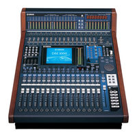
Yamaha MB1000 Service Manual (308 pages)
DIGITAL PRODUCTION CONSOLE/ PEAK METER BRIDGE/WOODEN SIDE PANELS
Brand:
Yamaha
| Category:
Music Mixer
| Size: 51.45 MB
Table of Contents
1
Contents
3
Lithium Battery Handling
4
Specifications
7
EQ Parameters
7
Gate Parameters
8
Comp Parameters
9
Analog Input Spec
9
Analog Output Spec
9
Libraries
10
Digital Input Spec
10
Digital Output Spec
11
Control I/O Spec
11
I/O Slot Spec (1-2)
12
CONTROL Port
12
REMOTE Port
13
Dimensions
13
Front View
13
Side View
13
Top View
14
Control Panel
14
Dm1000
14
Panel Layout
15
AD Input Section
15
Channel Strip Section
16
AUX SELECT Section
16
ENCODER MODE Section
16
FADER MODE Section
16
STEREO Section
17
DISPLAY ACCESS Section
17
Display Section
18
LAYER Section
18
SCENE MEMORY Section
18
SELECTED CHANNEL Section
19
Data Entry Section
19
Headphones & Talkback Section
19
USER DEFINED KEYS Section
20
AD Input and Output Section
20
MONITOR Section
20
Rear Panel
21
Digital I/O & Control Section
21
Power Section
21
SLOT Section
22
Controls
23
Bottom Assembly
23
Circuit Board Layout
24
Dca
25
Rear Assembly U
26
Control Panel Asembly
27
Front Panel Assembly
27
Rear Panel Assembly
28
Disassembling the DM1000
28
Disassembly Procedure
28
Removing the MB1000
28
Removing the SP1000
30
Bottom Assembly Section
30
DCA 1/5 Circuit Board
30
DCA 2/5, 3/5 and 4/5 Circuit Boards
30
DCD Circuit Board
31
JK1 Circuit Board
31
JK2 Circuit Board
31
MAIN Circuit Board
31
Replacing the Lithium Battery
34
AC Circuit Board
34
AC Inlet Assembly
34
AC Shield Plate
34
Power Transformer
36
ADA Circuit Board
36
Rear Assembly U Section
36
XLR Circuit Board
38
HAAD 1/2 Circuit Board
38
HAAD 2/2 Circuit Board
38
Heat Sink
38
PC Support
39
Control Panel Assembly Section
39
FD Circuit Board
40
LCD Circuit Board
40
PN1 (1/4) Circuit Board
40
PN1 (2/4 Meter) Circuit Board
40
PN1 (4/4 Encoder) Circuit Board
42
Encoder Angle Bracket
43
Lcd
44
Disassembling the MB1000
44
PN Circuit Board
46
Installing an Optional Card
47
Lsi Pin Description
48
Hd6417709Sf133 (X2081A00) Cpu (Sh3)
49
Sh7042 (X4409A00) Cpu (Sub)
50
MBCG46183-129PFV-G (XV833A00) Gate Array (SIO4)
50
SGH603064F-62F (XV973A00) Gate Array
51
YSS910-S (XV988A00) DSP6 (Digital Signal Processor)
52
YSS919-H (XZ693A00) DSP7 (Digital Signal Processor)
53
Mbcg61594-130 (X3299A00) Atsc2A
54
CS8405A-CS (XZ349A00) DIT (Digital Audio Interface Transmitter)
54
YM3436DK (XG948E0) DIR2 (Digital Format Interface Receiver)
55
CS8420 (XW559A00) SRC (Sample Rate Converter)
55
S1D13704F00A100 (X3498A00) LCDC (LCD Controller)
56
AK4393-VF-E2 (XW029A00) DAC (Digital to Analog Converter)
56
CS5361-KS (X3447A00) ADC (Analog to Digital Converter)
56
ICS2008BV-T (X2832B00) T.C. Reader/Generator
57
Sh7042 (X4409A00) Cpu (Sh-2)
58
IC Block Diagram
63
Tlc2932Ipwr (Xv064A00)
64
Sn75C1168N Sr (Xu073A00)
64
Tc74Hc238Af (Xt163A00)
64
Tc74Hc245Af (Xs720A00)
64
Td62M8600F (Xv014A00)
65
Circuit Boards
65
DCD
66
DCCOM (AC) Circuit Board
66
DCCOM (DCA 2/5) Circuit Board
80
JKCOM (JK1) Circuit Board
82
JKCOM (OPT) Circuit Board
92
PNCOM (PN1 (1/4)) Circuit Board
103
Fader Inspection
103
Group Inspection
103
Inspections
103
Writing Programs
104
Ch in 1~16
104
Omni in 1~4
104
Phones out L/R
106
DIGITAL IN/OUT Inspection
107
Dissuing Sound
107
Jitter Measurement
107
Word Clock Ext
107
WORD CLOCK IN, 2TR DIGITAL in 1 and 2 PLL
115
Dm1000/Mb1000 Service Check Program
115
List of Check Items
115
Screen Explanation
116
Common Contents
116
PLLP2 Test
116
Service Check
116
Service Check Connection Diagram
117
2TR IN/OUT (DIO) Test
117
LCD Test
117
MIDI Test
117
WORD CLOCK Test
118
FADER Tsense Test
118
PANEL ALL LED Test
118
PANEL LED Test
118
PANEL SW Test
119
ENCODER (CH) Test
119
ENCODER (Etc.) Test
119
Example of Execution Screen
120
Message Log
120
METER LED Test
120
METER SW Test
121
Panel SW Operation Order Screen
121
Supplement
122
SW Operation
123
LED Lighting Order
124
Audio Check
124
Check Method
124
Limits
124
Startup Method
125
Check Contents
143
How to Start the Inspection Program
143
Inspection Items
143
Mb1000 Test Program
143
Switch Inspection
145
Initializing the Dm1000
146
Transmitting Parameter Settings Via MIDI (Bulk Dump)
150
Calibrating the Faders
150
Checking the Battery and the System Version
151
MIDI Data Format
152
Program Change
166
MIDI Implementation Chart
167
Parts List
168
Overall Assembly
169
MAIN-JK1 Wiring
176
Bottom View
183
Electrical Parts
239
Front Panel Assembly
240
Rear Panel Assembly
250
Circuit Diagram
250
Table of Contents
251
Ada (002, 003)
251
Block Diagram 002 (Dm1000)
252
Block Diagram 003 (Dm1000)
253
Block Diagram 004 (Dm1000)
254
Haad (002~004)
255
Block Diagram 006 (Dm1000)
256
Block Diagram 007 (Dm1000)
257
Jk1 (002~005)
257
Jk2
257
Main (002~013)
257
Opt
257
Overall Connector Circuit Diagram (Dm1000)
258
Ac Circuit Diagram (Dm1000)
259
Dca Circuit Diagram (Dm1000)
260
DCD Circuit Diagram (Dm1000)
261
Fd Circuit Diagram 002 (Dm1000)
262
Fd Circuit Diagram 003 (Dm1000)
263
Fd Circuit Diagram 004 (Dm1000)
264
Fd Circuit Diagram 005 (Dm1000)
265
Fd Circuit Diagram 006 (Dm1000)
266
Fd Circuit Diagram 007 (Dm1000)
267
Fd Circuit Diagram 008 (Dm1000)
268
Fd Circuit Diagram 009 (Dm1000)
269
Fd Circuit Diagram 010 (Dm1000)
270
Ada Circuit Diagram 002 (Dm1000)
271
Ada Circuit Diagram 003 (Dm1000)
272
Haad Circuit Diagram 002 (Dm1000)
273
Haad Circuit Diagram 003 (Dm1000)
274
Haad Circuit Diagram 004 (Dm1000)
275
Jk1 Circuit Diagram 002 (Dm1000)
276
Jk1 Circuit Diagram 003 (Dm1000)
277
Jk1 Circuit Diagram 004 (Dm1000)
278
Jk1 Circuit Diagram 005 (Dm1000)
279
Jk2 Circuit Diagram (Dm1000)
280
Opt Circuit Diagram (Dm1000)
281
Main Circuit Diagram 002 (Dm1000)
282
Main Circuit Diagram 003 (Dm1000)
283
Main Circuit Diagram 004 (Dm1000)
284
Main Circuit Diagram 005 (Dm1000)
285
Main Circuit Diagram 006 (Dm1000)
286
Main Circuit Diagram 007 (Dm1000)
287
Main Circuit Diagram 008 (Dm1000)
288
Main Circuit Diagram 009 (Dm1000)
289
Main Circuit Diagram 010 (Dm1000)
290
Main Circuit Diagram 011 (Dm1000)
291
Main Circuit Diagram 012 (Dm1000)
292
Main Circuit Diagram 013 (Dm1000)
293
Lcd Circuit Diagram (Dm1000)
294
Pn1 (002~006)
294
Pn1 Circuit Diagram 002 (Dm1000)
295
Pn1 Circuit Diagram 003 (Dm1000)
296
Pn1 Circuit Diagram 004 (Dm1000)
297
Pn1 Circuit Diagram 005 (Dm1000)
298
Pn1 Circuit Diagram 006 (Dm1000)
299
Pn2 Circuit Diagram (Dm1000)
300
Xlr Circuit Diagram (Dm1000)
302
Block Diagram (Mb1000)
303
Overall Connector Circuit Diagram (Mb1000)
304
Main Circuit Diagram 002 (Mb1000)
305
Main Circuit Diagram 003 (Mb1000)
306
Pn Circuit Diagram 002 (Mb1000)
307
Pn Circuit Diagram 003 (Mb1000)
Advertisement
Yamaha MB1000 Owner's Manual (3 pages)
Peak Meter Bridge for the DM1000 Digital Production Console
Brand:
Yamaha
| Category:
Measuring Instruments
| Size: 0.08 MB
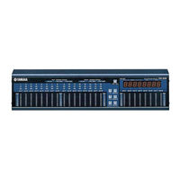
Yamaha MB1000 Owner's Manual (2 pages)
Peak Meter Bridge for the DM1000 Digital Production Console
Brand:
Yamaha
| Category:
Music Equipment
| Size: 0.07 MB
Advertisement
Share and save
Advertisement
Related Products
Yamaha MB02R96
Yamaha MB2000
Yamaha MC2410M
Yamaha MW12
Yamaha M3000-24
Yamaha M3000A
Yamaha MC2408M
Yamaha MG8
Yamaha MGP12X
Yamaha M7CL-48ES
Yamaha Categories
Motorcycle
Musical Instrument
Electronic Keyboard
Receiver
Amplifier
More Yamaha Manuals
Login
Sign In
OR
Sign in with Facebook
Sign in with Google
Upload manual
Upload from disk
Upload from URL