Sign In
Upload
Manuals
Brands
WinGD Manuals
Engine
X82-B
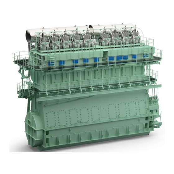
WinGD X82-B Marine Engine Manuals
Manuals and User Guides for WinGD X82-B Marine Engine. We have
2
WinGD X82-B Marine Engine manuals available for free PDF download: Maintenance Manual
WinGD X82-B Maintenance Manual (841 pages)
Brand:
WinGD
| Category:
Engine
| Size: 54 MB
Table of Contents
Table of Contents
3
1 Introduction
22
Maintenance Manual - Change Record
22
Change Record
22
Preface
24
Technical Documentation Set
26
Technical Documentation Set
27
Data Module Codes (Procedural Data)
28
Data Module Codes (Procedural Data)
29
Data Module Codes (Descriptive Data)
30
Data Module Codes (Illustrated Parts Data)
32
About this Book
34
About the Engine
36
Group 1 - Engine Frame and Bearings
36
Group 2 - Cylinder
36
Group 3 - Crankshaft, Connecting Rod and Piston
36
Group 5 - Supply Unit, Pumps and Control Valves
36
Group 6 - Scavenge Air Components
36
Group 7 - Cylinder Lubrication
36
Group 8 - Pipes
36
Group 9 - Monitoring Instruments
36
Side View (Generic)
37
End View (Generic, Seen from the Driving End)
38
Engine Numbering (Generic)
40
List of Abbreviations
42
List of Abbreviations and Acronyms
42
2 Safety
47
Safety Precautions and Safety Rules
48
3 General Data for Maintenance
51
Lifting Tools
52
Lifting Capacities (for Information Only)
53
RUD-Eye Bolts
53
RUD-Swivel Lugs
55
Jointing Compounds
56
Jointing Compound
56
Clearances - General
58
Clearances
60
Crankshaft and Thrust Bearing - Clearances
60
Crankshaft and Thrust Bearing
60
Crankshaft and Main Bearings
61
Crankshaft and Main Bearing
61
Crosshead Guide
63
Cylinder Liner
64
Piston Rod Gland
65
Exhaust Valve - Spindle and Guide Bush
66
Exhaust Valve
66
Connecting Rod - Top and Bottom End Bearings
67
Piston and Piston Rings
68
Supply Unit - Drive Wheels
70
Fuel and Servo Pump Units
72
Fuel Pump
74
Fuel Pump
75
Torque Values - Standard Screws
76
Torque Value - Applicable Decrease
76
4 General Maintenance Procedures
79
Do Maintenance Work - General Procedure
80
Tighten a Round Nut with a Pre-Tensioner
82
Loosen a Round Nut with a Pre-Tensioner
86
Do a Check of the Pre-Tension
90
5 Maintenance Schedule
93
Maintenance Schedule
94
6 Group 1 - Engine Frame and Bearings
95
Foundation Bolts
96
Bedplate - Do a Check of the Foundation Bolts
96
Main Bearing - Bearing Shell Number
98
Main Bearing - Bearing Shell - No. 1 - Prepare before Removal
98
Main Bearing - Bearing Shell - No. 1 - Remove
100
Crankshaft and Flywheel - Lift
102
Crankshaft and Flywheel
102
Bearing Shell - Remove
104
Bearing Shell - Lift
105
Main Bearing Shell - No.1 - Do a Check
108
Main Bearing - Bearing Shell - No. 1 - Install
110
Supports
110
Bearing Shell - Move
115
Crankshaft and Flywheel - Lift
116
Main Bearing - Bearing Shell Number 2 to
118
Main Bearing - Bearing Shell - No. 2 to # - Prepare before Removal
118
Main Bearing - Bearing Shell - No. 2 to # - Remove
120
Bearing Shell No_2_To_N
125
Main Bearing Shell - No.2 to # - Examine
130
Main Bearing - Bearing Shell - No. 2 to # - Install
132
Bearing Shell_Move
135
Main Bearing Cover - No. 1
140
Main Bearing Cover - No.1 - Remove
140
Cover and Oil Pipe
142
Thrust Device
143
Bearing Cover
144
Bearing Cover - Move
145
Main Bearing Cover - No.1 - Install
146
Main Bearing Cover - No. 2 to
146
Thrust Device
147
Bearing Cover - Install
148
Bearing Cover - Oil Pipe
150
Main Bearing Cover - No. 2 to # - Remove
152
Oil Pipe and Round Nuts
154
Thrust Device
155
Roller Support
156
Bearing Cover No.2 to # - Lift and Lower
157
Bearing Cover No. 2 to # - Remove
158
Main Bearing Cover - No. 2 to #- Install
160
Thrust Device
162
Bearing Cover No.2 to # - Install
164
Thrust Bearing
166
Thrust Bearing - Examine the Housing
166
Visual Examination
167
Thrust Bearing - Do a Check of the Axial Clearance with a Dial Gauge
168
Axial Clearance
169
Thrust Bearing - Do a Check of the Axial Clearance with a Inside Micrometer
170
Axial Clearance - Micrometer
171
Thrust Bearing - Remove the Pads
174
Cover - Remove
175
Thrust Pad - Removal
177
Thrust Bearing - Install the Pads
180
Thrust Pad - Install
182
Thrust Pads - Configuration
183
Cover - Install
184
Engine Stays
186
Engine Stays (Friction Shims) - Do a Check of the Pre-Tension
186
Engine Stays (Hydraulic) - Do a Check of the Oil Pressure
188
Engine Stays - Pressure Check
189
Tie Rod
190
Tie Rod - Do a Check of the Pre-Tension
190
Pre-Tension Checks
191
Tie Rod - Remove
192
Tie Rod - Removal
193
Tie Rod - Install
194
Tie Rod - Apply Tension
196
7 Group 2 - Cylinder
197
Cylinder Liner
200
Cylinder Liner - Do a Check of the Bore
200
Cylinder Liner - Dimension Check
203
Cylinder Liner - Remove
206
Water Guide Jacket
208
Cylinder Liner (Example) - Move
210
Cylinder Liner - Preserve
212
Cylinder Liner - Storage
213
Cylinder Liner - Grind
216
Cylinder Liner - Grind the Lubricating Groove
218
Lubricating Grooves - Grind
219
Cylinder Liner - Grind the Scavenge Ports
220
Scavenge Ports - Grind
221
Cylinder Liner - Install
222
Insulation Bandage
223
Lubricating Quill
228
Lubricating Quill - Remove
228
Lubricating Quill - Do a Functional Test
230
Lubricating Quill - Install
232
Sealing Surface
233
Piston Rod Gland
236
Piston Rod Gland - Remove
236
Piston Rod Gland - Remove and Install
237
Piston Rod Gland - Disassemble
238
Piston Rod Gland - Do a Check of the Wear
240
Piston Rod Gland - Install
242
Piston Rod Gland - Assemble
244
Cylinder Cover
246
Cylinder Cover - Remove
246
Cylinder Cover - Pipes and Expansion Piece (Example)
248
Lifting Tool - Pre-Tensioner (Example)
249
Cylinder Cover, Exhaust Valve Cage and Water Guide Jacket (Example)
250
Cylinder Cover and Exhaust Valve Cage (Example)
251
Cylinder Cover - Grind the Sealing Face for Injection Valve
252
Fuel Injection Valve Position - Grind
254
Cylinder Cover - Install
256
Assemble before Installation (Example)
258
Conventional Injection Valve
262
Conventional Injection Valve - Remove
262
Injection Valve - Removal
263
Conventional Injection Valve - Prepare before the Test
264
Preparation of Injection Valve for Test
265
Conventional Injection Valve - Do a Functional Test
266
Conventional Injection Valve - Adjust
270
Adjust the Opening Pressure of the Injection Valve (X82 or X82-B)
271
Conventional Injection Valve - Disassemble
272
Injection Valve (Example) - Disassemble
274
Nozzle Tip (Example) - Replace
276
Conventional Injection Valve - Assemble
278
Nozzle Body - Installation
279
Injection Valve (Example) - Assemble
281
Conventional Injection Valve - Install
284
Injection Valve (Example) - Install
285
Starting Air Valve
288
Starting Air Valve - Remove
288
Starting Air Valve - Preparation
289
Starting Air Valve - Removal
290
Starting Air Valve - Disassemble
292
Starting Air Valve - Grind
294
Starting Air Valve - Assemble
296
Starting Air Valve - Install
298
Starting Air Valve - Installation
299
Exhaust Valve
300
Exhaust Valve - Remove
300
Exhaust Valve - Preparation
301
Exhaust Valve - Removal
302
Exhaust Valve - Disassemble
304
Guide Bush - Removal
307
Exhaust Valve - Remove the Seat (Recommended Procedure)
308
Valve Seat - Remove
309
Exhaust Valve - Remove the Seat (Alternative Procedure)
310
Valve Seat - Alternative Procedure
311
Exhaust Valve - Do a Check of the Seat
312
Exhaust Valve, Clearance
313
Valve Seat Clearance
314
Exhaust Valve - Grind the Seat
316
Valve Seat - Grinding Tool
317
Exhaust Valve - Install the Seat
318
Valve Seat - Install
319
Exhaust Valve - Assemble
320
Guide Bush - Installation
321
Valve Spindle - Installation
323
Damper Settings
324
Damper Setting (Example)
324
Valve Stroke Sensor, Throttle and Non-Return Valve
325
Exhaust Valve - Install
328
Exhaust Valve - Installation
329
Expansion Piece - Installation
330
Exhaust Valve - Complete the Installation
331
8 Group 3 - Crankshaft, Connecting Rod and Piston
333
Connecting Rod
333
Crankshaft
336
Crankshaft - Do a Check of the Crank Deflection
336
Dial Gauge Position
337
Crank Positions for Clockwise Direction
338
Maximum Permitted Difference in MM
339
Definitions of Positions
339
Crank-Web Deflection Limits in MM
340
Definition of Deflection
341
Crankshaft - Install the Work Platform
342
Crankshaft - Remove the Work Platform
344
Torsional Vibration Damper
346
Torsional Vibration Damper - Examine
346
Axial Vibration Damper
348
Axial Vibration Damper - Disassemble
348
Axial Vibration Damper - Housing and Pipes
349
Axial Vibration Damper - Move
351
Axial Vibration Damper - Assemble
352
Axial Vibration Damper - Install
354
Axial Vibration Damper - Bolts
355
Turning Gear
358
Turning Gear - Do a Check of the Screwed Connections
358
Turning Gear - Do a Check
358
Turning Gear - Lubricate the Teeth
360
Turning Gear and Gear Wheels
361
Recommended Suppliers
362
Connecting Rod
364
Connecting Rod - Prepare before Removal
364
Stop Plate
364
Connecting Rod - Remove
368
Connecting Rod - Move
371
Connecting Rod - Move 2
375
Connecting Rod - Install
378
Connecting Rod - Move 2
380
Crosshead - Install
386
Toggle Lever - Attach
387
Piston - Attach
388
Connecting Rod - Remove the Top End Bearing
390
Top End Bearing - Remove
391
Connecting Rod - Remove the Bottom End Bearing
392
Bottom End Bearing Cover - Move
394
Bottom End Bearing Shell - Remove
395
Bottom End Bearing
397
Top Bearing Shell - Remove
398
Connecting Rod - Examine the Bearing Shells
400
Connecting Rod - Install the Bottom End Bearing
402
Top Bearing Shell - Move
405
Bottom End Bearing
406
ISO VG 1000/1500 Suppliers
407
Bottom End Bearing - Install
409
ISO VG 1000/1500 Suppliers
410
Connecting Rod - Install the Top End Bearing
412
Top End Bearing - Move
414
Crosshead - Lower
415
Bearing Lubrication
416
Connecting Rod - Remove the Top End Bearing Cover
418
Equipment - Install
421
Top Bearing Cover - Removal
422
Connecting Rod - Install the Top End Bearing Cover
424
Top Bearing Cover - Move
425
Crosshead
425
Top Bearing Cover - Install
427
Crosshead - Remove
430
Toggle Lever - Remove
432
Crosshead Bearing - Temperature Sensor
433
Tools - Prepare
434
Bracket - Attach
435
Tools - Attach
436
Connecting Rod - Move
437
Crosshead - Move
438
Crosshead - Remove
439
Crosshead - Remove
441
Guide Shoes - Remove
442
Crosshead - Do a Check of the Clearances
444
Clearance Checks
445
Dimensions Check
446
Crosshead - Install
448
Guide Shoe - Move
450
Guide Shoes - Install
452
Tools - Remove
455
Piston
458
Piston (Installed) - Do Checks of the Surface and Clearances
458
Top Surface - Dimensions Check
459
Piston Ring - Clearance
460
Piston - Prepare before Removal
462
Piston - Preparation
463
Piston - Preparation before Removal (Example)
465
Piston - Remove
468
Piston - Disassemble
472
Piston - Preparation before Disassembly
473
Piston (Removed) - Do Checks of the Surface and Clearances
476
Piston Groove Clearance - Calliper Gauge
477
Piston - Assemble
480
Torque Values
481
Piston - Install
484
Piston - Move (Example)
485
Piston Rod Gland - Attach (Example)
487
Piston Ring
490
Piston Ring - Remove
490
Piston Ring - Remove (Example)
491
Piston Ring - Examine
492
Piston Rings - Measure
493
Examples of Wear Rate
494
Examples of Remaining Service Life
494
Equation Wear Rate
494
Equation Service Time
494
Chrome Ceramic Layer
495
Piston Ring Groove (Piston Installed) - Do a Check with a Ring Piece
496
Piston Ring Groove (Piston Removed) - Do a Check with a Calliper Gauge
498
Piston Ring Groove (Piston Removed) - Do a Check
500
Piston Groove Clearance - Ring Piece
501
Piston Ring - Install
502
Piston Rings - Install (Example)
503
Piston Ring - Do the Preservation
504
9 Group 4 - Supply Unit Drive and Control Components
507
Group 4 - Supply Unit Drive and Control
507
Driving Wheels
508
Gear Wheel Crankshaft - Examine the Teeth
508
Gear Wheel Crankshaft - Do a Check of the Teeth Backlash
510
Driving Wheel - Gear Tooth Backlash
512
Driving Wheel Gear Train - Monitor the Condition
514
Shut-Off Valve for Starting Air
516
Shut-Off Valve for Starting Air - Disassemble
516
Shut-Off Valve for Starting Air - Prepare for Disassembly
517
Shut-Off Valve for Starting Air - Disassemble
519
Shut-Off Valve for Starting Air - Assemble
522
Shut-Off Valve for Starting Air - Do a Test of the Operation
526
Shut-Off Valve for Starting Air - Operation Test
528
10 Group 5 - Supply Unit, Pumps and Control Valves
529
Servo Oil Pump
530
Servo Oil Pump - Do a Check for Wear and Damage
530
Servo Oil Pump - Remove
532
Servo Oil Pump - Install
536
Fuel Pump
540
Fuel Pump - Remove
540
Fuel Pump - Disassemble
544
Guide Pin Removal
545
Guide Piston and Roller Removal
546
Toothed Rack Removal
547
Pump Cylinder Removal
548
Non-Return Valve Removal
549
Fuel Pump - Assemble
550
Pump Cylinder Installation
551
Pump Cover Installation
552
Toothed Rack Assembly
553
Pump Plunger and Bottom Housing Assembly
554
Plunger Position Check
555
Fuel Pump - Install
558
Fuel Pump Installation
559
Fuel Pump - Do a Test of the Operation
562
Fuel Pump - Oil Flow
563
Fuel Pump Actuator
566
Fuel Pump Actuator - Calibrate
566
Calibration Illustration
567
Fuel Pump Actuator - Adjust
570
Actuator - Adjust
571
Actuator - Adjust -2
572
Fuel Pressure Control Valve
574
Fuel Rail - Remove the Pressure Control Valve
574
Pressure Control Valve - Remove
575
Fuel Rail - Do a Check of the Pressure Control Valve
576
PCV - Do a Check
577
Fuel Rail - Install the Pressure Control Valve
580
Pressure Control Valve - Install
581
Fuel Overpressure Safety Valve
582
Fuel Rail - Remove the Overpressure Safety Valve
582
Fuel Rail - Do a Check of the Overpressure Safety Valve
584
Fuel Overpressure Safety Valve - Pressure Check
586
Fuel Rail - Install the Overpressure Safety Valve
588
Fuel Overpressure Safety Valve - Installation
589
Injection Control Unit
590
Injection Control Unit - Remove
590
ICU - Move
593
Injection Control Unit - Install
594
ICU - Connect Pipes
596
Injection Control Unit - Do the Preservation
598
Supply Unit
600
Supply Unit Camshaft and Bearing Shell - Prepare before Removal
600
Rollers - Lift
602
Oil Baffle
603
Supply Unit Camshaft and Bearing Shell - Remove
604
Bearing Shells - Remove
605
Camshaft - Remove
606
Supply Unit Camshaft and Bearing Shell - Install
608
Camshaft
608
Camshaft - Install
610
Oil Baffle - Install
611
Supply Unit Bearing Bush - Remove
612
Bearing Bushes
613
Supply Unit Bearing Bush - Install
614
Supply Unit Camshaft and Bearing Shell - Do the Follow-On Work
616
Filling Piece
617
Exhaust Valve Control Unit
620
Exhaust Valve Control Unit (VCU) - Remove
620
Exhaust Valve Control Unit - Remove
621
Exhaust Valve Control Unit (VCU) - Disassemble
622
Exhaust Valve Control Unit - Disassemble/Assemble
623
Exhaust Valve Control Unit (VCU) - Assemble
624
Exhaust Valve Control Unit (VCU) - Install
626
Exhaust Valve Control Unit - Install
627
Distance X for VCU
628
Connection Piece of VCU
628
11 Group 6 - Scavenge Air Components
631
Scavenge Air Receiver
632
Scavenge Air Receiver - Examine
632
Scavenge Air Receiver - Visual Examination
634
Level Switches and Filters
635
Scavenge Air Receiver - Do a Check of the Relief Valve
636
Relief Valve
637
Scavenge Air Receiver - Remove the Flaps
638
Flaps - Remove
639
Scavenge Air Receiver - Install the Flaps
640
Flaps - Install
641
Auxiliary Blower
642
Auxiliary Blower - Remove
642
Electric Motor (Driving End) - Move
643
Electric Motor (Driving End) - Remove
644
Electric Motor (Free End) - Move
645
Auxiliary Blower - Install
648
Auxiliary Blower - Move
650
Electric Motor (Free End) - Install
651
Auxiliary Blower (Driving End) Move
652
Electric Motor (Driving End) - Install
653
Scavenge Air Cooler
654
Scavenge Air Cooler - Remove
654
Scavenge Air Cooler (Example) - Prepare
656
Scavenge Air Cooler - Install
662
Scavenge Air Cooler (Example) - Prepare for Installation
664
Scavenge Air Cooler (Example) - Follow up Front and Rear Side
665
Water Separator
666
Water Separator - Remove
666
Water Separator - View 1
667
Water Separator - View 2
668
Water Separator - View 3
669
Water Separator - View 4
670
Water Separator - View 5
671
Water Separator - Install
672
Water Separator - View 6
673
Water Separator - View 7
674
12 Group 7 - Cylinder Lubrication
677
Cylinder Lubrication System
678
Cylinder Lubrication System - Do a Functional Test
678
Cylinder Lubrication System - Bleed
680
Cylinder Lubricating Pump - Remove
684
Cylinder Lubricating Pump (Pulse) - Examine
688
Cylinder Lubricating Pump - Examine
690
Cylinder Lubricating Pump - Install
692
13 Group 8 - Pipes
695
HP Servo Oil Pipe
696
HP Servo Oil Pipe - Remove
696
Servo Oil Pipes - Remove
698
HP Servo Oil Pipe - Grind the Sealing Face
700
HP Servo Oil Pipe - Grind and Adjust
702
HP Servo Oil Pipe - Install
704
Servo Oil Pipes - Install
706
Hydraulic Pipe Exhaust Valve
708
Hydraulic Pipe Exhaust Valve - Remove
708
Hydraulic Pipe (Exhaust Valve) - Remove
708
Hydraulic Pipe Exhaust Valve - Grind the Sealing Face
712
Hydraulic Pipe (Exhaust Valve) - Grind Sealing Face
714
Hydraulic Pipe Exhaust Valve - Install
716
Hydraulic Pipe (Exhaust Valve) - Install
716
HP Fuel Pipe
720
HP Fuel Pipe (Fuel Rail to Injection Valve) - Remove
720
HP Fuel Pipe (Fuel Rail to Injection Valve) - Grind the Sealing Face
724
HP Fuel Pipe (Fuel Rail to Injection Valve) - Grind
724
HP Fuel Pipe (Fuel Rail to Injection Valve) - Install
728
HP Fuel Pipe (Fuel Pump to Fuel Rail) - Remove
732
HP Fuel Pipe Fuel Pump to Fuel Rail - Prepare
734
HP Fuel Pipe (Fuel Pump to Fuel Rail) - Prepare
735
HP Fuel Pipe (Fuel Pump to Fuel Rail) - Grind the Sealing Face
740
HP Fuel Pipe (Fuel Pump to Fuel Rail) - Sealing Face - Grind
742
HP Fuel Pipe (Fuel Pump to Fuel Rail) - Install
744
HP Fuel Pipe (Fuel Pump to Fuel Rail) - Views
746
14 Group 9 - Monitoring Instruments
751
Crank Angle Sensor Unit
752
Crank Angle Sensor Unit (Flywheel) - Proximity Sensor - Remove
752
Proximity Sensor (Flywheel) - Remove
754
Crank Angle Sensor Unit (Flywheel) - Proximity Sensor - Install
756
Proximity Sensor (Flywheel) - Install
758
Crank Angle Sensor Unit (Supply Unit) - Proximity Sensor - Remove
760
Proximity Sensor - Remove
762
Crank Angle Sensor Unit (Supply Unit) - Proximity Sensor - Install
764
Proximity Sensor - Install
766
15 Tools
769
General for Tools
770
Standard Tools
772
Recommended Tools
814
Advertisement
WinGD X82-B Maintenance Manual (606 pages)
Brand:
WinGD
| Category:
Engine
| Size: 32 MB
Table of Contents
0330-1/A1
5
Table of Contents
8
General
10
Spare Parts
10
General Safety Precautions
22
General
32
Crankshaft and Thrust Bearing
33
Clearance Table
33
Crankshaft and Main Bearing
35
Crosshead Guide
37
Cylinder Liner
39
Piston Rod Gland
41
Exhaust Valve
43
Top and Bottom End Bearings to Connecting Rod
45
Piston Cooling and Crosshead Lubricating Link
47
Piston and Piston Rings
49
Driving Wheels for Supply Unit
51
Fuel and Servo Pump Units
53
Fuel Pump
55
Bedplate and Tie Rod Group
82
Bedplate and Thrust Bearing Checking the Foundation Bolts
84
1112−1/A1
84
Main Bearing
88
1132−1/A1
88
1132−2/A1
92
Thrust Bearing
110
Checking the Axial Clearance
110
1224−1/A1
112
1903−1/A1
118
Cylinder Liner and Cylinder Cover Group
124
Cylinder Liner
124
2124−1/A1
127
2124−2/A1
128
2124−2/A2
138
2124−3/A1
148
2303−1/A1
158
Cylinder Cover
168
2708−2/A1
172
Injection Valve with FAST
178
2728−1/A1
190
2745−1/A1
196
Exhaust Valve
200
2751−1/A1
200
2751−2/A1
206
2751−3/A1
214
2751−4/A1
219
Crankshaft, Connecting Rod and Piston Group
220
3103−1/A1
222
Vibration Damper
226
3130−1/A1
227
Inspection (GEISLINGER Vibration Damper)
230
3140−1/A1
234
Connecting Rod
250
3303−1/A1
251
3303−2/A1
252
3303−3/A1
264
3303−4/A1
272
3303−5/A1
288
Crosshead
292
3326−1/A1
292
3326−2/A1
296
Piston
306
3403−1/A1
306
3403−1/A2
316
3403−2/A1
330
3403−3/A1
334
3403−4/A1
341
3425−1/A1
342
Driving Wheels and Shut-Off Valve for Starting Air
350
Group 4
350
Driving Wheels
350
4103−1/A1
350
4103−2/A1
356
4325−1/A1
362
Supply Unit, Injection and Exhaust Valve Control
368
Group 5
368
Fuel Pump
368
5556−1/A1
370
5556−2/A1
390
5562−1/A1
394
5562−2/A1
400
5564−1/A1
404
Fuel Pump Unit
408
5581−1/A1
408
5581−2/A1
414
Fuel Pump Actuator
416
Servo Pump Unit
424
5612−1/A1
432
Scavenge Air Receiver and Auxiliary Blower
436
Group 6
436
6420−1/A1
438
Auxiliary Blower Maintenance
442
6545−1/A1
442
6606−1/A1
446
6606−1/A2
458
6708−1/A1
464
Cylinder Lubrication Group
476
7218−1/A2
478
Group 8
482
Exhaust Waste Gate (Low-Load Tuning)
484
Selective Catalytic Reduction System
486
SCR Valve − Removal and Installation
488
8155−1/A1
488
HP Servo Oil Pipe
494
8460−1/A1
500
HP Fuel Pipe
507
8733−1/A1
507
Crank Angle Sensor Unit, Tools
526
Group 9
526
9223−1/A1
528
9403−2/A1
534
Hydraulic Pre-Tensioning Jacks
538
Overview, Storing, Servicing and Maintenance
538
9403−3/A1
539
General Application Instructions
552
9403−4/A1
552
Tool List
556
9403−5/A1
556
Standard Tools
556
Recommended Special Tools
599
Advertisement
Related Products
WinGD X72
WinGD X92DF
WinGD X72DF
WinGD X62DF
WinGD X72-B
WinGD X35-B
WinGD X92-B
WinGD X92
WinGD X62DF-S2.0
WinGD W-X82
WinGD Categories
Engine
Marine Equipment
Industrial Equipment
More WinGD Manuals
Login
Sign In
OR
Sign in with Facebook
Sign in with Google
Upload manual
Upload from disk
Upload from URL