Sign In
Upload
Manuals
Brands
WinGD Manuals
Engine
X35-B
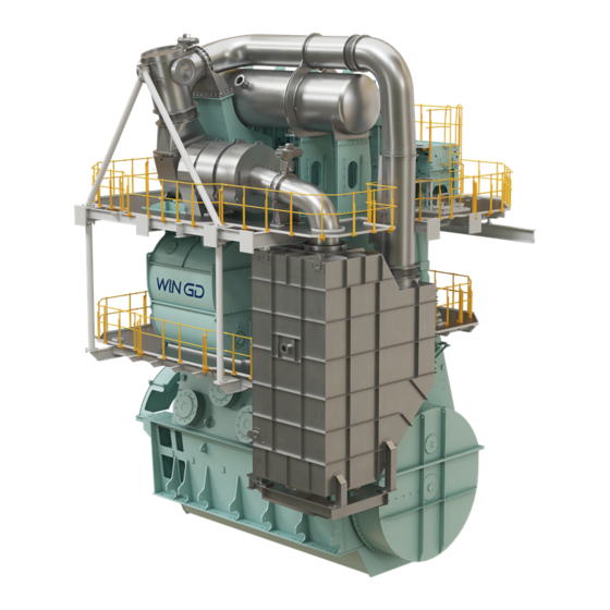
User Manuals: WinGD X35-B Marine Engine
Manuals and User Guides for WinGD X35-B Marine Engine. We have
1
WinGD X35-B Marine Engine manual available for free PDF download: Operation Manual
WinGD X35-B Operation Manual (486 pages)
Brand:
WinGD
| Category:
Engine
| Size: 13 MB
Table of Contents
Table of Contents
3
List of Tables
9
Change Record
18
Operation Manual - Change Record
18
Technical Documentation Set
22
Technical Documentation Set
23
Data Module Codes (Descriptive Data)
24
Data Module Codes (Procedural Data)
26
About this Book
28
About the Engine
30
Side View (Generic)
31
End View (Generic, Seen from the Driving End)
32
Engine Numbering (Generic)
34
List of Abbreviations
36
List of Abbreviations and Acronyms
36
Safety
41
Safety Precautions and Safety Rules
42
Contamination and Fire in the Scavenge Air Spaces
46
Fire-Fighting in the Scavenge Air Space
48
Explosions in the Crankcase
50
Prevent Explosions in the Crankcase
52
Access to Engine Spaces
54
Design and Function of the Engine
57
Short Description of the Engine
58
Pressure - Volume Diagram and Schematic of the Two-Stroke Diesel Cycle
59
Operating Range
60
Use of the Engine
60
Tuning Options
62
The Relation between Engine and Propeller
64
Schematic Diagram - Relation Speed/Power (FPP)
65
Schematic Diagram - Relation Speed/ Power (CPP)
67
Design and Function of Systems
69
General for Systems
70
Line Codes
70
Line Codes for Systems
70
Cooling Water System
72
Cooling Water System (Generic and Simplified)
73
Wash-Water System
74
System Oil System
76
System Oil System (Generic and Simplified)
77
Servo Oil System
78
Servo Oil System (Generic and Simplified)
79
Cylinder Oil System
80
Cylinder Oil System (Generic and Simplified, with and Without Icat)
81
Starting Air System
82
Starting Air System (Generic and Simplified)
83
Scavenge Air System
84
Control Air System
86
Control Air System (Generic and Simplified)
87
Exhaust Gas System
88
Exhaust Gas System (Generic and Simplified)
89
Fuel System
90
Fuel System with FLV (Generic and Simplified)
92
Fuel System with ICU (Generic and Simplified)
93
HP Selective Catalytic Reduction System
94
HP SCR System - Layout
95
Operation Limits of Exhaust Gas Temperature after Exhaust Gas Manifold
96
HP SCR System - Emergency Bypass
97
HP SCR System - Change from Tier III to Bypass
98
HP SCR System - Purging and Venting
99
HP SCR System - Preparation
101
HP SCR System - Tier III
102
Control Box E48
103
Control Box E49
103
Hp Scr
103
HP SCR System - Principal Control Configuration
103
Control Box E50
106
Hp Scr System Status (Main Page)
107
Page - HP SCR SYSTEM STATUS (MAIN PAGE)
107
Hp Scr System Overview
108
Page - HP SCR SYSTEM OVERVIEW
108
Hp Scr Interfaces
109
Page - HP SCR INTERFACES
109
Hp Scr Manual Valve Control
110
Page - HP SCR MANUAL VALVE CONTROL
110
Hp Scr Software Info
111
Page - HP SCR SOFTWARE INFO
111
Page - HP SCR
112
LP Selective Catalytic Reduction System
114
LP SCR Temperature Controlled (Example)
115
LP SCR Bypass Rate Controlled (Example)
116
LP SCR Control System Layout
118
LP SCR System - Principal Control Configuration
119
Control Box E70 with Option SPC
120
Control Box E71 with Option SPC
121
Control Boxes E72 and E73
122
Lp Scr System Status (Main Page)
123
Page - LP SCR SYSTEM STATUS (MAIN PAGE)
123
Lp Scr System Overview
124
Page - LP SCR SYSTEM OVERVIEW
124
Lp Scr Interfaces
125
Page - LP SCR INTERFACES
125
Lp Scr Software Info
126
Page - LP SCR SOFTWARE INFO
126
Lp Scr Page Index
127
Page - LP SCR
127
Example of SPC
128
Steam Production Control System
128
Page - STEAM PRODUCTION CONTROL
129
Operation Manual 5 Design and Function of Components
131
Design and Function of Components
131
Bedplate
134
Group 1 - Engine Frame and Bearings
134
Main
136
Main Bearing
136
Main Bearing (Generic)
136
Thrust Bearing
138
Thrust Bearing (Generic)
139
Monoblock Column
140
Tie Rod
142
Cylinder Liner
144
Group 2 - Cylinder
144
Cylinder - Cooling Water Outlet (Generic)
145
Lubricating Quill
146
Piston Rod Gland
148
Direct Controlled Injection Valve
150
Starting Valve
152
Exhaust Valve
154
Exhaust Valve (Generic)
154
Crankshaft
156
Group 3 - Crankshaft, Connecting Rod and Piston
156
Torsional Vibration Damper
158
Axial Vibration Damper
162
Axial Vibration Damper (Generic)
162
Turning Gear
164
Connecting Rod and Connecting Rod Bearing
166
Connecting Rod and Connecting Rod Bearing (Generic)
166
Crosshead and Guide Shoe
168
Piston
170
Group 4 - Supply Unit Drive and Control Components
172
Supply Unit Drive
172
Starting Air Shut-Off Valve
174
Starting Air Shut-Off Valve (Example)
174
Control Air Supply
176
Control Air Supply (Generic)
176
Local Maneuvering Stand
178
Control System
179
Pick-Up for Speed Measurement
180
Group 5 - Supply Unit, Pumps and Control Valves
182
Servo Oil Pump
182
Supply Unit
184
Fuel Pump
186
Pressure Control Valve
188
Pressure Control Valve - Location (Example)
189
Flow Limiting Valve
190
Exhaust Valve Control Unit
192
Group 6 - Scavenge Air Components
194
Scavenge Air Receiver
194
Scavenge Air Receiver - Cross Section (Example)
195
Turbocharger
196
Auxiliary Blower
198
Auxiliary Blower Switch Box
200
Switch Box (Generic)
200
Scavenge Air Cooler
202
Cylinder Lubrication
206
Usual Vertical Oil Supply
207
Crank Angle Sensor Unit on Intermediate Wheel (Example)
210
Crank Angle Sensor Unit on Flywheel (Example)
211
Oil Mist Detector - Schematic Diagram (Example)
213
Operation Manual 6 Control System
215
Control System
215
Engine Control System
216
ECS Modules
217
Signal Flow Diagram
220
Intelligent Combustion Control
222
ICC - Pressure Diagram
223
ICC - Control Schematic
224
Local Display Unit (LDU-20) - General
226
Overview
226
Color Display - General Items
227
Local Display Unit (LDU-20) - Pages
228
Page - MAIN
228
Pages - General
228
Control Locations
234
Page - CONTROL LOCATIONS
234
Control Locations
235
Ca Sensor Status
236
Page - CA SENSOR STATUS
236
Page - FUEL SYSTEM
238
Cylinder Balancing Diesel
240
Page - CYLINDER BALANCING DIESEL
240
Cylinder Balancing Diesel
241
Main Fuel Injection
242
Page - MAIN FUEL INJECTION
242
Page Index
244
Exhaust Valves
246
Page - EXHAUST VALVES
246
Failure List
248
Page - FAILURE LIST
248
Page - CYLINDER LUBRICATION
250
Page - USER PARAMETERS
252
User Parameters
252
Page - PERFORMANCE DATA DIESEL
254
Performance Data Diesel
254
Page - TEMPERATURES
256
Page - SOFTWARE INFO
258
Software Info
258
Log Messages
260
Page - LOG MESSAGES
260
Log Entry Data
262
Page - LOG ENTRY DATA
262
Page - SYSTEM STATUS
264
System Status
264
Page - SOFTWARE TOOLS
266
Software Tools
266
Page - SYSTEM SETTINGS
268
System Settings
268
Page - ETHERNET
270
Page - DATE
272
Page - SCAVENGE AIR - EWG (Optional)
274
SCAVENGE AIR - EWG (Optional)
274
Page - SCREENSHOT
276
Operate the Local Display Unit (LDU-20)
278
Navigation Menu
279
Cooling Water System with Bypass Cooling
290
Cooling Water System Without Bypass Cooling
291
Cooling Water System with Circulation
292
Cylinder Lubricant Quantity
316
Service During Operation
341
Do an Analysis of the System Oil
342
Do an Analysis of the Cylinder Oil
344
Location of Ball Valves - Dirty Oil Samples
345
Replace the Filter Element of the Duplex Filter
348
Clean the Turbocharger During Operation
350
Clean the Scavenge Air Cooler During Operation
352
SAC - Clean During Operation (Example)
353
Do a Test of the Exhaust Waste Valve
356
Feed Rate Adjustments - Running-In
358
Running-In of New Components - General
358
Running-In of New Components
360
Damper Oil Supply Pressure Upstream of the Axial Vibration Damper Is too Low
366
Servo Oil Pressure in the Distributor Pipe (Mini Rail) Is Not in the Permitted Range
366
Temperature Difference of the Fuel Outlet of the Two Fuel Pumps Is too High (for X35 or X40 Engine)
367
Cylinder Cooling Water Temperature Downstream of a Cylinder Is too High
369
Supply Pressure of the Cooling Water to the SAC Is too Low
369
Supply Pressure of the Cylinder Cooling Water Is too Low
369
Supply Temperature of the Cylinder Cooling Water Is too Low
369
Supply Temperature of the Cooling Water to the SAC Is too Low
370
Temperature of the Cooling Water Downstream of the SAC Is too High
370
Lubricating Oil Supply Pressure at the Engine Inlet Is too Low
371
Lubricating Oil Supply Pressure Upstream of the Crossheads Is too Low
371
Lubricating Oil Supply Pressure Upstream of the Injectors Is too Low
371
Lubricating Oil Supply Temperature at the Engine Inlet Is too High
371
Bearing Oil Temperature at a Bearing Outlet Is too High
372
Oil Mist Concentration Is too High
372
Servo Oil Flow at a Servo Oil Pump Inlet Is too Low
372
Servo Oil Leakage Flow from the Servo Oil Supply Unit Is too High
372
Piston Cooling Oil Flow to a Piston Is Not in the Permitted Range
373
Piston Cooling Oil Temperature Downstream of a Piston Is too High
373
TC Bearing Oil Supply Pressure Upstream of a Turbocharger Is too Low
373
TC Bearing Oil Temperature at a Turbocharger Inlet Is too High (External Oil Supply)
373
TC Bearing Oil Temperature at a Turbocharger Outlet Is too High
373
Cylinder Oil Flow Is too Low
374
Cylinder Oil Supply Pressure Is too Low
374
Damper Oil Supply Pressure Upstream of the Torsional Vibration Damper Is too Low
374
Fuel Leakage Flow from Fuel Rail Items Is too High (Engine with FLV)
375
Fuel Leakage Flow from the Fuel Supply Unit Is too High
375
Fuel Supply Pressure at the Engine Inlet Is too Low
375
Fuel Supply Temperature Is Not in the Permitted Range
375
Leakage Flow from the Rail Unit Is too High
375
Fuel Leakage Flow from Fuel Rail Items Is too High (Engine with ICU)
376
Fuel Pressure in the Fuel Rail Is too High (for X35 or X40 Engine)
376
Fuel Pressure in the Fuel Rail Is too Low (for X35 or X40 Engine)
376
Difference Pressure of Pilot Fuel Filter Is too High
377
Gas Concentration in Piston Underside Is too High
377
Gas Supply Pressure Is too Low
377
Exhaust Gas Temperature Difference Downstream of All Cylinders Is too High
378
Exhaust Gas Temperature Downstream of a Cylinder Is too High
378
Exhaust Gas Temperature Upstream of a Turbocharger Is too High
378
Exhaust Gas Temperature Downstream of a Turbocharger Is too High
379
Exhaust Valve Does Not Operate, Unwanted Noise
379
Smoke Is too Dark
379
Scavenge Air Pressure Is too High
380
Scavenge Air Pressure Is too Low
380
Scavenge Air Temperature in the Receiver Is too High
380
Scavenge Air Temperature in the Receiver Is too Low
380
Condensation Flow at a Water Separator Is too High
381
Condensation Flow Upstream of a Water Separator Is too High
381
Pressure of the Air Spring Air Supply Is too High
381
Scavenge Air Temperature in the Piston Underside Is too High
381
Starting Air Supply Pressure Is too Low
381
Control Air Supply Pressure Is too Low (Safety Supply)
382
Control Air Supply Pressure Is too Low (Stand-By Supply)
382
Control Air Supply Pressure Is too Low (Usual Supply)
382
Oil Leakage Flow in the Collector for Leakage Oil from the Air Spring Is too High
382
Pressure of the Air Spring Air Supply Is too Low
382
A Fuel Pump Actuator Has a Failure
383
Cylinder Liner Wall Temperature Is too High
383
Temperature of a Thrust Bearing Pad Is too High
383
Power Supply to the Power Supply Box E85 Has a Failure
384
Unwanted Engine Speed Decrease
384
Unwanted Engine Stop
384
Examples of Failure Messages
386
Failure Messages
386
Special Failures
387
Example of Inspection Point
389
Supply Unit (Example) and Example of Inspection Point
393
Leakage on FLV and Pipes (Example)
399
Exhaust Valve with Pressure Element
407
Not All Turbochargers Are Defective (Example)
411
All Turbochargers Are Defective (Example)
412
Exhaust Waste Gate (Example)
415
SCR System - Covers (Example for 1 Turbocharger)
421
SCR System - Covers (Example for 2 Turbocharger)
422
Technical Data
427
Engine Data
428
General Data
428
Rated Power
429
List of Usual Values and Safeguard Settings - General
430
Function Code
432
Signal Codes
432
Applied System
433
Function Group
433
Fuel System
434
List of Usual Values and Safeguard Settings
434
Cooling Water Systems (XX10NN to XX19NN)
435
Oil Systems (XX2NNN, Part 1)
436
Oil Systems (XX2NNN, Part 2)
437
Oil Systems (XX2NNN, Part 3 (Turbocharger Bearing Oil))
438
Oil Systems (XX2NNN, Part 4)
439
Exhaust Gas System (XX37NN)
441
Air Systems (XX40NN to XX44NN)
442
Miscellaneous Items (XX45NN to XX52NN)
443
Engine Cross Section
446
Section Views
446
Engine Longitudinal Section
447
Schematic Diagrams
455
Schematic Diagrams
456
Process Codes
457
Applied System
459
Function Group
459
Color Codes and Symbols - Electric Connection Diagram
460
Ethernet
463
Advertisement
Advertisement
Related Products
WinGD X72
WinGD X82-B
WinGD X92DF
WinGD X72DF
WinGD X62DF
WinGD X72-B
WinGD X92-B
WinGD X92
WinGD X62DF-S2.0
WinGD W-X82
WinGD Categories
Engine
Marine Equipment
Industrial Equipment
More WinGD Manuals
Login
Sign In
OR
Sign in with Facebook
Sign in with Google
Upload manual
Upload from disk
Upload from URL