Sign In
Upload
Manuals
Brands
WinGD Manuals
Engine
X92DF
WinGD X92DF Manuals
Manuals and User Guides for WinGD X92DF. We have
1
WinGD X92DF manual available for free PDF download: Operation Manual
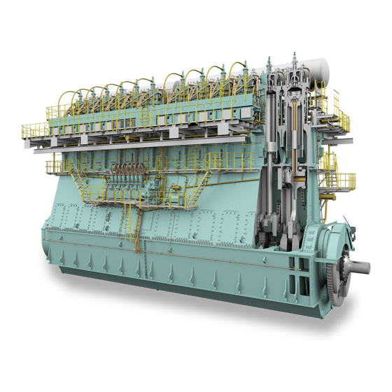
WinGD X92DF Operation Manual (608 pages)
Brand:
WinGD
| Category:
Engine
| Size: 18 MB
Table of Contents
Table of Contents
3
List of Tables
9
Introduction
19
Change Record
20
Technical Documentation Set
24
Data Module Codes (Descriptive Data)
26
Data Module Codes (Procedural Data)
28
About this Book
30
About the Engine
32
Side View (Generic)
33
End View (Generic, Seen from the Driving End)
34
Engine Numbering (Generic)
36
List of Abbreviations
38
List of Abbreviations and Acronyms
38
2 Safety
43
Safety Precautions and Safety Rules
44
Safety Precautions and Safety Rules for Natural Gas
48
Contamination and Fire in the Scavenge Air Spaces
50
Fire-Fighting in the Scavenge Air Space
52
Explosions in the Crankcase
54
Prevent Explosions in the Crankcase
56
Prevention of Explosions in the Exhaust Gas System (Gas Mode)
58
Exhaust Ventilation
59
Access to Engine Spaces
60
Design and Function of the Engine
63
Short Description of the DF Engine
64
Pressure - Volume Diagram and Schematic of the Two-Stroke Diesel Cycle
65
Pressure - Volume Diagram and Schematic of the Two-Stroke Otto Cycle
66
Use of the Engine
68
Operating Range
68
Tuning Options
70
The Relation between Engine and Propeller
72
Schematic Diagram - Relation Speed/Power (FPP)
73
Schematic Diagram - Relation Speed/ Power (CPP)
75
4 Design and Function of Systems
77
General for Systems
78
Line Codes for Systems
78
Line Codes
78
Cooling Water System
80
Cooling Water System (Generic and Simplified)
81
Wash-Water System
82
Wash-Water System (Generic and Simplified)
83
System Oil System
84
System Oil System (Generic and Simplified)
85
Servo Oil System
86
Servo Oil System (Generic and Simplified)
87
Injection Control Unit (ICU)
87
Cylinder Oil System
88
Starting Air System
90
Starting Air System (Generic and Simplified)
91
Scavenge Air System
92
Control Air System
94
Control Air System (Generic and Simplified)
95
Exhaust Gas System
96
Exhaust Gas System (Generic and Simplified)
97
Fuel System
98
Fuel System with FLV (Generic and Simplified)
100
Fuel System with ICU (Generic and Simplified)
101
Gas System
102
Gas System (Generic and Simplified)
103
Pilot Fuel System
104
LP Selective Catalytic Reduction System
106
LP SCR Temperature Controlled (Example)
107
LP SCR Bypass Rate Controlled (Example)
108
LP SCR Control System Layout
110
LP SCR System - Principal Control Configuration
111
Control Box E70 with Option SPC
112
Control Box E71 with Option SPC
113
Control Boxes E72 and E73
114
Lp Scr System Status (Main Page)
115
Page - LP SCR SYSTEM STATUS (MAIN PAGE)
115
Lp Scr System Overview
116
LDU-20 Page - LP SCR SYSTEM OVERVIEW
116
Lp Scr Interfaces
117
LDU-20 Page - LP SCR INTERFACES
117
Lp Scr Software Info
118
LDU-20 Page - LP SCR SOFTWARE INFO
118
Lp Scr Page Index
119
Page - LP SCR
119
HP Selective Catalytic Reduction System
120
HP SCR System - Layout
121
Operation Limits of Exhaust Gas Temperature after Exhaust Gas Manifold
122
HP SCR System - Emergency Bypass
123
HP SCR System - Change from Tier III to Bypass
124
HP SCR System - Purging and Venting
125
HP SCR System - Preparation
127
HP SCR System - Tier III
128
Hp Scr
129
HP SCR System - Principal Control Configuration
129
Control Box E48
129
Control Box E49
129
Control Box E50
132
Hp Scr System Status (Main Page)
133
Page - HP SCR SYSTEM STATUS (MAIN PAGE)
133
Hp Scr System Overview
134
LDU-20 Page - HP SCR SYSTEM OVERVIEW
134
Hp Scr Interfaces
135
LDU-20 Page - HP SCR INTERFACES
135
Hp Scr Manual Valve Control
136
LDU-20 Page - HP SCR MANUAL VALVE CONTROL
136
Hp Scr Software Info
137
LDU-20 Page - HP SCR SOFTWARE INFO
137
Page - HP SCR
138
Example of SPC
140
Steam Production Control System
140
LDU-20 Page - STEAM PRODUCTION CONTROL
141
LDU for the Steam Boost Mode
143
5 Design and Function of Components
145
Group 1 - Engine Frame and Bearings
148
Bedplate
148
Main
150
Main Bearing (Generic)
150
Main Bearing
150
Thrust Bearing
152
Thrust Bearing (Generic)
153
Monoblock Column
154
Tie Rod
156
Group 2 - Cylinder
158
Cylinder Liner
158
Cylinder - Cooling Water Outlet (Generic)
159
Lubricating Quill (Generic)
160
Lubricating Quill
160
Gas Admission Valve
162
Piston Rod Gland
164
Conventional Injection Valve
166
Starting Valve
168
Relief Valve
170
Exhaust Valve (Generic)
172
Exhaust Valve
172
Pilot Injection Valve
174
Group 3 - Crankshaft, Connecting Rod and Piston
176
Crankshaft
176
Torsional Vibration Damper
178
Axial Vibration Damper (Generic)
182
Axial Vibration Damper
182
Turning Gear
184
Connecting Rod and Connecting Rod Bearing (Generic)
186
Connecting Rod and Connecting Rod Bearing
186
Crosshead and Guide Shoe
188
Piston
190
Group 4 - Supply Unit Drive and Control Components
192
Supply Unit Drive
192
Starting Air Shut-Off Valve (Example)
194
Starting Air Shut-Off Valve
194
Control Air Supply (Generic)
196
Control Air Supply
196
Local Maneuvering Stand
198
Local Maneuvering Stand - Option a
198
Local Maneuvering Stand - Option B
200
Local Maneuvering Stand - Option C
202
Pick-Up for Speed Measurement
204
Group 5 - Supply Unit, Pumps and Control Valves
206
Servo Oil Pump
206
Supply Unit
208
Supply Unit Pilot Fuel
210
Fuel Pump
212
Fuel Pump - Cross Section (Example)
213
Injection Control Unit
214
Pressure Control Valve
216
Pressure Control Valve - Location (Example)
217
Flow Limiting Valve
218
Exhaust Valve Control Unit
220
Group 6 - Scavenge Air Components
222
Scavenge Air Receiver
222
Scavenge Air Receiver - Cross Section (Example)
223
Turbocharger
224
Auxiliary Blower
226
Switch Box (Generic)
228
Auxiliary Blower Switch Box
228
Scavenge Air Cooler
230
Water Separator
232
Cylinder Lubricating Pump
234
Cylinder Lubrication
234
Group 7 - Cylinder Lubrication
234
Usual Vertical Oil Supply
235
Effect of Second Order Moments (M2V) of the Engine
236
Integrated Electrical Balancer (Ielba)
236
Ielba - Function
237
Ielba - Control Cabinet
239
Ielba - Error Indication
241
Group 8 - Pipes
242
Exhaust Waste Gate
242
Crank Angle Sensor Unit on Intermediate Wheel (Example)
244
Group 9 - Monitoring Instruments
244
Crank Angle Sensor Unit
244
Crank Angle Sensor Unit on Flywheel (Example)
245
Water in Oil Monitor
246
Oil Mist Detector
248
Oil Mist Detector - Schematic Diagram (Example)
249
6 Control System
251
Engine Control System UNIC
254
ECS Modules
255
Signal Flow Diagram
258
Engine Control System WECS-9520
260
Engine Control System Wice
270
Intelligent Combustion Control
274
ICC - Pressure Diagram
275
ICC - Control Schematic
276
Gas Valve Unit and External Gas Supply System
278
Gvu-Ed
279
Gvu-Od
280
GVU Control Panel
281
GVU-OD: Schematic Diagram for Installation
281
Fuel Gas Removal from the Fuel Gas Pipes: Schematic Diagram
283
Igpr - Schematic Diagram
284
Integrated Gas Pressure Regulation
284
LDU-20 - Overview
288
Local Display Unit (LDU-20) - General
288
LDU-20 Color Display - General Items
289
Local Display Unit (LDU-20) - Option for UNIC - Pages
290
Operate the Local Display Unit (LDU-20)
290
LDU-20 - Navigation Menu
291
LDU-20 Pages - General for DF Engine
296
LDU-20 Page - MAIN
298
Control Locations
302
LDU-20 Page - CONTROL LOCATIONS
302
Control Locations
303
Fuel Mode Control
304
Page - FUEL MODE CONTROL
304
Ca Sensor Status
306
Page - CA SENSOR STATUS
306
Cylinder Balancing Diesel
308
Page - CYLINDER BALANCING DIESEL
308
Cylinder Balancing Diesel
309
Cylinder Balancing Gas
310
LDU-20 Page - CYLINDER BALANCING GAS
310
Cylinder Balancing Gas
311
Page - CYLINDER LUBRICATION
312
LDU-20 Page - Icat
314
Page - DYNAMIC COMBUSTION CONTROL (DCC)
318
Exhaust Ventilation
320
LDU-20 Page - EXHAUST VENTILATION
320
Exhaust Valves
322
LDU-20 Page - EXHAUST VALVES
322
Failure List
324
LDU-20 Page - FAILURE LIST
324
Failure Simulation
326
Page - FAILURE SIMULATION
326
Failure Simulation
327
Page - FUEL SHARING (if Applicable)
328
Fuel System
330
LDU-20 Page - FUEL SYSTEM
330
Gas Pressure
332
LDU-20 Page - GAS PRESSURE
332
Gas Admission Valves
334
Page - GAS ADMISSION VALVES
334
Gav Manual Valve Test
336
LDU-20 Page - GAV MANUAL VALVE TEST
336
Gvu & Valve Test
338
LDU-20 Page - GVU & VALVE TEST
338
Knock Control
340
LDU-20 Page - KNOCK CONTROL
340
Knock Control
341
Log Messages
342
Page - LOG MESSAGES
342
Main Fuel Injection
344
LDU-20 Page - MAIN FUEL INJECTION
344
Page Index
346
Performance Data Diesel
348
LDU-20 Page - PERFORMANCE DATA DIESEL
348
Performance Data Gas
350
LDU-20 Page - PERFORMANCE DATA GAS
350
Pilot Fuel Injection
352
LDU-20 Page - PILOT FUEL INJECTION
352
Pilot Fuel Pressure
354
Page - PILOT FUEL PRESSURE
354
SCAVENGE AIR - EWG (Optional)
356
Page - SCAVENGE AIR - EWG (Optional)
356
LDU-20 Page - SCREENSHOT
358
Software Info
360
LDU-20 Page - SOFTWARE INFO
360
Imo Crc Info
362
LDU-20 Page - IMO CRC INFO
362
Software Tools
364
LDU-20 Page - SOFTWARE TOOLS
364
System Status
366
LDU-20 Page - SYSTEM STATUS
366
System Settings
368
LDU-20 Page - SYSTEM SETTINGS
368
LDU-20 Page - TEMPERATURES
370
User Parameters
372
LDU-20 Page - USER PARAMETERS
372
Gas Leak Test
374
LDU-20 Page - GAS LEAK TEST
374
Log Entry Data
376
LDU-20 Page - LOG ENTRY DATA
376
Page - DATE
378
LDU-20 Page - ETHERNET
380
Ielba Control
382
Page - Ielba Control (Optional)
382
Ielba Control
383
Manual Control Panel (MCP) - Option for Wice - Pages
384
Operate the Manual Control Panel (MCP)
384
MCP Page - MAIN Locked
385
MCP Page - SYSTEM INFO
388
MCP Page - SYSTEM INFO - Option for Wice
388
System Info
388
MCP Page - TREND
390
MCP Page - TREND - Option for Wice
390
MCP Page - FUEL MODE CONTROL
392
MCP Page - FUEL MODE CONTROL - Option for Wice
392
MCP Page - GAS SYSTEM
394
MCP Page - MAIN
396
MCP Page - INSTRUMENTS
398
MCP Page - Adjust User Parameter
400
MCP Page - Adjust User Parameters
400
MCP Page - Open User Parameters
400
MCP Page - Select User Parameter
401
MCP Page - FUEL / LUBRICATION SYSTEM
404
Fuel / Lubrication System
405
Local Control Cabinet
406
Local Control Cabinet - General
406
Function Buttons of the Manual Control Panel (MCP)
407
Navigation Menu of the Manual Control Panel (MCP)
407
Manual Control Panel (MCP) - Option for WECS-9520 - Pages
410
Do Regular Checks for WECS-9520
410
WECS-9520 Manual Control Panel
412
User Parameters
416
User Parameters and Maintenance Settings for WECS-9520
416
Maintenance Settings
418
Failure ID and LED Indications on FCM-20
420
Failures and Defects of WECS-9520 Components
420
Failures of Pulse Lubrication
421
WECS-9520 Failure Groups
421
LED Color Codes
422
Red Fail LED and Two-Digit LED Display
422
Examples of Failure Ids
423
8 Operation
427
Prepare the Engine before Start - General
428
Prepare the Engine before Start
430
Cooling Water System with Bypass Cooling
432
Cooling Water System Without Bypass Cooling
433
Cooling Water System with Circulation
434
Start the Engine - General
438
Start the Engine
440
Do Checks During Operation - General
442
Do Checks During Operation
444
Do Regular Safety Checks
448
Maneuver the Ship - General
452
Maneuver the Ship
454
Change-Over the Diesel Fuel - General
456
Cylinder Lubricant Quantity
458
Change-Over to and from Gas - General
460
Change-Over the Diesel Fuel Automatically
462
Change-Over from HFO to MDO Manually
464
Change-Over from MDO to HFO Manually
466
Change-Over to and from Gas
468
Stop the Engine - General
470
Stop the Engine
472
Emergency Stop the Engine - General
474
Emergency Stop the Engine
476
Prepare the Engine after Stop - General
478
Prepare the Engine for a Short Service Break
480
Prepare the Engine for Standstill Maintenance
482
9 Service During Operation
487
Do an Analysis of the System Oil
488
Do an Analysis of the Cylinder Oil
490
Location of Ball Valves - Dirty Oil Samples
491
Replace the Filter Element of the Duplex Filter
494
Clean the Turbocharger During Operation
496
Clean the Scavenge Air Cooler During Operation
498
SAC - Clean During Operation (Example)
499
Do a Test of the Exhaust Waste Valve
502
Feed Rate Adjustments - Running-In
504
Running-In of New Components - General
504
Running-In of New Components
506
10 Troubleshooting
509
Troubleshooting - General Data
510
Servo Oil Pressure in the Distributor Pipe (Mini Rail) Is Not in the Permitted Range
512
Damper Oil Supply Pressure Upstream of the Axial Vibration Damper Is too Low
512
Malfunctions of Systems and Components
512
Temperature Difference of the Fuel Outlet of the Two Fuel Pumps Is too High (for X35/-B or X40/-B Engine)
513
Supply Pressure of the Cylinder Cooling Water Is too Low
515
Supply Temperature of the Cylinder Cooling Water Is too Low
515
Cylinder Cooling Water Temperature Downstream of a Cylinder Is too High
515
Supply Pressure of the Cooling Water to the SAC Is too Low
515
Supply Temperature of the Cooling Water to the SAC Is too Low
516
Temperature of the Cooling Water Downstream of the SAC Is too High
516
Lubricating Oil Supply Pressure at the Engine Inlet Is too Low
517
Lubricating Oil Supply Pressure Upstream of the Injectors Is too Low
517
Lubricating Oil Supply Temperature at the Engine Inlet Is too High
517
Lubricating Oil Supply Pressure Upstream of the Crossheads Is too Low
517
Servo Oil Leakage Flow from the Servo Oil Supply Unit Is too High
518
Servo Oil Flow at a Servo Oil Pump Inlet Is too Low
518
Bearing Oil Temperature at a Bearing Outlet Is too High
518
Oil Mist Concentration Is too High
518
Piston Cooling Oil Temperature Downstream of a Piston Is too High
519
Piston Cooling Oil Flow to a Piston Is Not in the Permitted Range
519
TC Bearing Oil Temperature at a Turbocharger Outlet Is too High
519
TC Bearing Oil Supply Pressure Upstream of a Turbocharger Is too Low
519
TC Bearing Oil Temperature at a Turbocharger Inlet Is too High (External Oil Supply)
519
Damper Oil Supply Pressure Upstream of the Torsional Vibration Damper Is too Low
520
Cylinder Oil Supply Pressure Is too Low
520
Cylinder Oil Flow Is too Low
520
Fuel Supply Temperature Is Not in the Permitted Range
521
Fuel Supply Pressure at the Engine Inlet Is too Low
521
Fuel Leakage Flow from the Fuel Supply Unit Is too High
521
Leakage Flow from the Rail Unit Is too High
521
Fuel Leakage Flow from Fuel Rail Items Is too High (Engine with FLV)
521
Fuel Leakage Flow from Fuel Rail Items Is too High (Engine with ICU)
522
Fuel Pressure in the Fuel Rail Is too High (for X35/-B or X40/-B Engine)
522
Fuel Pressure in the Fuel Rail Is too Low (for X35/-B or X40/-B Engine)
522
Gas Concentration in Piston Underside Is too High
523
Difference Pressure of Pilot Fuel Filter Is too High
523
Gas Supply Pressure Is too Low
523
Exhaust Gas Temperature Downstream of a Cylinder Is too High
524
Exhaust Gas Temperature Difference Downstream of All Cylinders Is too High
524
Exhaust Gas Temperature Upstream of a Turbocharger Is too High
524
Exhaust Gas Temperature Downstream of a Turbocharger Is too High
525
Exhaust Valve Does Not Operate, Unwanted Noise
525
Smoke Is too Dark
525
Scavenge Air Temperature in the Receiver Is too High
526
Scavenge Air Temperature in the Receiver Is too Low
526
Scavenge Air Pressure Is too High
526
Scavenge Air Pressure Is too Low
526
Condensation Flow at a Water Separator Is too High
527
Condensation Flow Upstream of a Water Separator Is too High
527
Scavenge Air Temperature in the Piston Underside Is too High
527
Starting Air Supply Pressure Is too Low
527
Pressure of the Air Spring Air Supply Is too High
527
Pressure of the Air Spring Air Supply Is too Low
528
Oil Leakage Flow in the Collector for Leakage Oil from the Air Spring Is too High
528
Control Air Supply Pressure Is too Low (Usual Supply)
528
Control Air Supply Pressure Is too Low (Stand-By Supply)
528
Control Air Supply Pressure Is too Low (Safety Supply)
528
Temperature of a Thrust Bearing Pad Is too High
529
Cylinder Liner Wall Temperature Is too High
529
A Fuel Pump Actuator Has a Failure
529
Power Supply to the Power Supply Box E85 Has a Failure
530
Unwanted Engine Speed Decrease
530
Unwanted Engine Stop
530
Examine the Supply Unit for Servo Oil Leakage
532
Example of Inspection Point
533
Examine the Supply Unit for Fuel Leakage
536
Supply Unit (Example) and Example of Inspection Point
537
Examine the Rail Unit for Leakage
540
Examine the ICU or Fuel Pipes for Fuel Leakage
542
Leakage on ICU and Pipes (Generic)
543
Leakage on Connecting Pipes (Generic)
545
Temporary Cut out a Defective Injection Valve
546
Temporary Cut out a Defective Exhaust Valve Drive
548
Temporary Isolate a Cylinder with Cooling Water Leakage
550
Exhaust Valve with Pressure Element
551
Disconnect the Fuel Pump
554
Fuel Pump (Example) - Isolate
555
Fuel Pump (Example) - Cut out
555
Connect the Fuel Pump
558
Fuel Pump (Example) - Connect
559
Fuel Pump (Example) - Cut in
559
Temporary Isolate a Defective Turbocharger
562
Not All Turbochargers Are Defective (Example)
563
All Turbochargers Are Defective (Example)
564
Temporary Isolate the Exhaust Waste Gate
566
Exhaust Waste Gate (Example)
567
Isolate a Defective Engine at Twin Engine Installation
570
11 Technical Data
573
General Data
574
Engine Data
574
Rated Power
575
List of Usual Values and Safeguard Settings - General
576
Function Code
578
Signal Codes
578
Function Group
579
Applied System
579
Fuel System
580
Gas System
580
Cooling Water Systems (XX10NN to XX19NN)
580
Oil Systems (XX2NNN, Part 1)
580
Exhaust Gas System (XX37NN)
580
Miscellaneous Items (XX45NN to XX52NN)
580
List of Usual Values and Safeguard Settings
580
Oil Systems (XX2NNN, Part 2)
583
Oil Systems (XX2NNN, Part 3 (Turbocharger Bearing Oil))
584
Oil Systems (XX2NNN, Part 4)
585
Gas System (XX33NN and XX39NN)
586
Fuel System (XX34NN)
587
Air Systems (XX40NN to XX44NN)
589
Failure Messages
591
Section Views (Generic Engine)
592
Cross Section
593
Longitudinal Section
594
12 Operating Media
595
Specifications for Gas Fuel
602
13 Schematic Diagrams
603
Schematic Diagrams
604
Process Codes
605
Function Group
607
Applied System
607
Color Codes and Symbols - Electric Connection Diagram
608
Advertisement
Advertisement
Related Products
WinGD X72
WinGD X82-B
WinGD X72DF
WinGD X62DF
WinGD X72-B
WinGD X35-B
WinGD X92-B
WinGD X92
WinGD X62DF-S2.0
WinGD W-X82
WinGD Categories
Engine
Marine Equipment
Industrial Equipment
More WinGD Manuals
Login
Sign In
OR
Sign in with Facebook
Sign in with Google
Upload manual
Upload from disk
Upload from URL