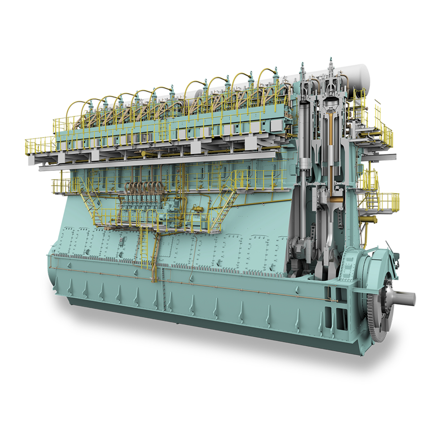
Sign In
Upload
Manuals
Brands
WinGD Manuals
Engine
X72
WinGD X72 Manuals
Manuals and User Guides for WinGD X72. We have
3
WinGD X72 manuals available for free PDF download: Maintenance Manual, Operation Manual
WinGD X72 Operation Manual (516 pages)
Brand:
WinGD
| Category:
Engine
| Size: 12 MB
Table of Contents
Table of Contents
3
List of Tables
9
Change Record
18
Operation Manual - Change Record
18
Technical Documentation Set
22
Technical Documentation Set
23
Data Module Codes (Descriptive Data)
24
Data Module Codes (Procedural Data)
26
Data Module Codes (Procedural Data)
27
About this Book
28
About the Engine
30
Main Bearing
31
Side View (Generic)
31
Engine Numbering (Generic)
32
List of Abbreviations
34
List of Abbreviations and Acronyms
34
Design and Function of the Engine
39
Short Description of the Engine
40
Pressure - Volume Diagram and Schematic of the Two-Stroke Diesel Cycle
41
Operating Range
42
Use of the Engine
42
Tuning Options
44
The Relation between Engine and Propeller
46
Schematic Diagram - Relation Speed/Power (FPP)
47
Safety
50
Safety Precautions and Safety Guidelines
50
Contamination and Fire in the Scavenge Air Spaces
54
Fire-Fighting in the Scavenge Air Space
56
Explosions in the Crankcase
58
Prevent Explosions in the Crankcase
60
Access to Engine Spaces
62
Design and Function of the Systems
65
General for Systems
66
Line Codes
66
Line Codes for Systems
66
Cooling Water System
68
Cooling Water System (Generic and Simplified)
69
Wash-Water System
70
System Oil System
72
Thrust Bearing
73
System Oil System (Generic and Simplified)
73
Servo Oil System
74
Cylinder Oil System
76
Lubricating Quill
76
Starting Air System
78
Starting Air Shut-Off Valve
78
Starting Air System (Generic and Simplified)
79
Scavenge Air System
80
Control Air System
82
Starting Valve
78
Control Air Supply
82
Exhaust Gas System
84
Fuel System
86
Supply Unit
86
Fuel Pump
88
Fuel System with FLV (Generic and Simplified)
88
Pressure Control Valve
89
Fuel System with ICU (Generic and Simplified)
89
HP Selective Catalytic Reduction System
90
HP SCR System - Layout
91
Operation Limits of Exhaust Gas Temperature after Exhaust Gas Manifold
92
HP SCR System - Emergency Bypass
93
HP SCR System - Change from Tier III to Bypass
94
HP SCR System - Purging and Venting
95
HP SCR System - Preparation
97
HP SCR System - Tier III
98
Hp Scr
99
HP SCR System - Principal Control Configuration
99
Control Box E48
99
Control Box E49
99
Control Box E50
102
Hp Scr System Status (Main Page)
103
Page - HP SCR SYSTEM STATUS (MAIN PAGE)
103
Hp Scr System Overview
104
Page - HP SCR SYSTEM OVERVIEW
104
Hp Scr Interfaces
105
Page - HP SCR INTERFACES
105
Hp Scr Manual Valve Control
106
Page - HP SCR MANUAL VALVE CONTROL
106
Hp Scr Software Info
107
Page - HP SCR SOFTWARE INFO
107
Page - HP SCR
108
LP Selective Catalytic Reduction System
110
LP SCR Temperature Controlled (Example)
111
LP SCR Bypass Rate Controlled (Example)
112
LP SCR Control System Layout
114
LP SCR System - Principal Control Configuration
115
Control Box E70 with Option SPC
116
Control Box E71 with Option SPC
117
Control Boxes E72 and E73
118
Lp Scr System Status (Main Page)
119
Page - LP SCR SYSTEM STATUS (MAIN PAGE)
119
Lp Scr System Overview
120
Page - LP SCR SYSTEM OVERVIEW
120
Lp Scr Interfaces
121
Page - LP SCR INTERFACES
121
Lp Scr Software Info
122
Page - LP SCR SOFTWARE INFO
122
Lp Scr Page Index
123
Page - LP SCR
123
Steam Production Control System
124
Example of SPC
124
Page - STEAM PRODUCTION CONTROL
125
LDU for the Steam Boost Mode
127
Synchro Phasing System
130
Page for Operation Mode "Control on
131
Page for Adjusting the Set Point
132
Page for Operation Mode "Off
133
Page for Operation Mode "Estimate Only
134
Page for Crank Angle and Speed States
135
4 Design and Function of the Components
137
Exhaust Valve Control Unit
137
Flow Limiting Valve
137
Fuel Pump Actuator
137
Group 6 - Scavenge Air System
137
Scavenge Air Receiver
137
Turbocharger
137
Auxiliary Blower
138
Auxiliary Blower Switch Box
138
Scavenge Air Cooler
138
Group 1 - Framework and Bearings
140
Bedplate
140
Main
142
Main Bearing (Generic)
142
Main Bearing
142
Thrust Bearing
144
Thrust Bearing (Generic)
145
Monoblock Column
146
Tie Rod
148
Cylinder - Cooling Water Outlet (Generic)
150
Group 2 - Cylinder
150
Cylinder Liner
150
Lubricating Quill
152
Piston Rod Gland
154
Direct Controlled Injection Valve
156
Starting Valve
158
Exhaust Valve (Generic)
160
Exhaust Valve
160
Group 3 - Crankshaft, Connecting Rod and Piston
162
Crankshaft
162
Torsional Vibration Damper
164
Axial Vibration Damper (Generic)
168
Axial Vibration Damper
168
Turning Gear
170
Connecting Rod and Connecting Rod Bearing (Generic)
172
Connecting Rod and Connecting Rod Bearing
172
Crosshead and Guide Shoe
174
Piston
176
Group 4 - Drive Supply Unit and Control Elements
178
Supply Unit Drive
178
Starting Air Shut-Off Valve (Example)
180
Starting Air Shut-Off Valve
180
Control Air Supply (Generic)
182
Control Air Supply
182
Local Maneuvering Stand for UNIC
184
Pick-Up for Speed Measurement
186
Group 5 - Supply Unit, Pumps and Control Valves
188
Servo Oil Pump
188
Supply Unit
190
Fuel Pump
192
Pressure Control Valve
194
Flow Limiting Valve
196
Exhaust Valve Control Unit
198
Fuel Pump Actuator
200
Group 6 - Scavenge Air System
202
Scavenge Air Receiver
202
Scavenge Air Receiver - Cross Section (Example)
203
Turbocharger
204
Switch Box (Generic)
208
Cylinder Lubrication
214
Cylinder Lubricating Pump
214
Effect of Second Order Moments (M2V) of the Engine
216
Ielba - Function
217
Ielba - Control Cabinet
219
Ielba - Control Cabinet
220
Ielba - Error Indication
221
Crank Angle Sensor Unit on Flywheel (Example)
225
Oil Mist Detector - Schematic Diagram (Example)
229
5 Control System of the Engine
231
Engine Control System UNIC
232
ECS Modules
233
Signal Flow Diagram
236
Intelligent Combustion Control
238
ICC - Pressure Diagram
239
ICC - Control Schematic
240
Local Display Unit (LDU-20) Pages for UNIC
242
Pages - General
242
Page - MAIN
242
Control Locations
248
Page - CONTROL LOCATIONS
248
Control Locations
249
Ca Sensor Status
250
Page - CA SENSOR STATUS
250
Cylinder Balancing Diesel
252
Page - CYLINDER BALANCING DIESEL
252
Cylinder Balancing Diesel
253
Page - CYLINDER LUBRICATION
254
Page - Icat
256
Dynamic Combustion Control (DCC)
260
Page - DYNAMIC COMBUSTION CONTROL (DCC)
260
Exhaust Ventilation
262
Page - EXHAUST VENTILATION
262
Exhaust Ventilation
263
Exhaust Valves
264
Page - EXHAUST VALVES
264
Failure List
266
Page - FAILURE LIST
266
Failure Simulation
268
Page - FAILURE SIMULATION
268
Failure Simulation
269
Fuel System
270
Page - FUEL SYSTEM
270
Knock Control
272
Page - KNOCK CONTROL
272
Knock Control
273
Log Messages
274
Page - LOG MESSAGES
274
Main Fuel Injection
276
Page - MAIN FUEL INJECTION
276
Performance Data Diesel
278
Page - PERFORMANCE DATA DIESEL
278
Pilot Fuel Injection
280
Page - PILOT FUEL INJECTION
280
Pilot Fuel Pressure
282
Page - PILOT FUEL PRESSURE
282
SCAVENGE AIR - EWG (Optional)
284
Page - SCAVENGE AIR - EWG (Optional)
284
Page - SCREENSHOT
286
Software Info
288
Page - SOFTWARE INFO
288
Imo Crc Info
290
Page - IMO CRC INFO
290
Software Tools
292
Page - SOFTWARE TOOLS
292
System Status
294
Page - SYSTEM STATUS
294
System Settings
296
Page - SYSTEM SETTINGS
296
Page - TEMPERATURES
298
User Parameters
300
Page - USER PARAMETERS
300
Log Entry Data
302
Page - LOG ENTRY DATA
302
Page - DATE
304
Page - ETHERNET
306
5.4 Control Pages for Other Systems
308
Overview
308
Local Display Unit (LDU-20) - General
308
Color Display - General Items
309
Operate the Local Display Unit (LDU-20)
310
Navigation Menu
311
Operation of the Engine
319
Cooling Water System with Bypass Cooling
324
Cooling Water System Without Bypass Cooling
325
Cooling Water System with Circulation
326
Cylinder Lubricant Quantity
350
Select: Prepare Tier III
375
Select: Tier III
376
Select: Tier II
377
Allowed Load During Cylinder Cut out
382
Turbocharger Cut out Procedure: Illustration 1
387
Turbocharger Cut out Procedure: Illustration 2
388
Turbocharger Cut out Procedure: Illustration 3
389
Turbocharger Cut out Procedure: Illustration 4
390
Turbocharger Cut out Procedure: Illustration 5
391
8 Service During Operation
393
Do an Analysis of the System Oil
394
Do an Analysis of the Cylinder Oil
396
Location of Ball Valves - Dirty Oil Samples
397
Feed Rate Adjustments - Running-In
400
Running-In of New Components - General
400
Running-In of New Components
402
Clean the Turbocharger During Operation
404
Clean the Scavenge Air Cooler During Operation
406
SAC - Clean During Operation (Example)
407
Replace the Filter Element of the Duplex Filter
410
Do a Test of the Exhaust Waste Valve
412
Supply Pressure of the Cylinder Cooling Water Is too Low
421
Supply Temperature of the Cylinder Cooling Water Is too Low
421
Cylinder Cooling Water Temperature Downstream of a Cylinder Is too High
421
Supply Pressure of the Cooling Water to the SAC Is too Low
421
Supply Temperature of the Cooling Water to the SAC Is too Low
422
Temperature of the Cooling Water Downstream of the SAC Is too High
422
Lubricating Oil Supply Pressure at the Engine Inlet Is too Low
423
Lubricating Oil Supply Pressure Upstream of the Injectors Is too Low
423
Lubricating Oil Supply Temperature at the Engine Inlet Is too High
423
Lubricating Oil Supply Pressure Upstream of the Crossheads Is too Low
423
Servo Oil Pressure in the Distributor Pipe (Mini Rail) Is Not in the Permitted Range
423
Servo Oil Leakage Flow from the Servo Oil Supply Unit Is too High
424
Servo Oil Flow at a Servo Oil Pump Inlet Is too Low
424
Bearing Oil Temperature at a Bearing Outlet Is too High
424
Oil Mist Concentration Is too High
424
Piston Cooling Oil Temperature Downstream of a Piston Is too High
425
Piston Cooling Oil Flow to a Piston Is Not in the Permitted Range
425
TC Bearing Oil Temperature at a Turbocharger Outlet Is too High
425
TC Bearing Oil Supply Pressure Upstream of a Turbocharger Is too Low
425
TC Bearing Oil Temperature at a Turbocharger Inlet Is too High (External Oil Supply)
425
Damper Oil Supply Pressure Upstream of the Torsional Vibration Damper Is too Low
426
Damper Oil Supply Pressure Upstream of the Axial Vibration Damper Is too Low
426
Cylinder Oil Supply Pressure Is too Low
426
Cylinder Oil Flow Is too Low
426
Fuel Supply Temperature Is Not in the Permitted Range
427
Fuel Supply Pressure at the Engine Inlet Is too Low
427
Fuel Leakage Flow from the Fuel Supply Unit Is too High
427
Temperature Difference of the Fuel Outlet of the Two Fuel Pumps Is too High
427
Leakage Flow from the Rail Unit Is too High
427
Fuel Leakage Flow from Fuel Rail Items Is too High (Engine with FLV)
427
Fuel Leakage Flow from Fuel Rail Items Is too High (Engine with ICU)
428
Fuel Pressure in the Fuel Rail Is too High (for X35/-B or X40/-B Engine)
428
Fuel Pressure in the Fuel Rail Is too Low (for X35/-B or X40/-B Engine)
428
Gas Concentration in Piston Underside Is too High
429
Difference Pressure of Pilot Fuel Filter Is too High
429
Gas Supply Pressure Is too Low
429
Exhaust Gas Temperature Downstream of a Cylinder Is too High
430
Exhaust Gas Temperature Difference Downstream of All Cylinders Is too High
430
Exhaust Gas Temperature Upstream of a Turbocharger Is too High
430
Exhaust Gas Temperature Downstream of a Turbocharger Is too High
431
Exhaust Valve Does Not Operate, Unwanted Noise
431
Smoke Is too Dark
431
Scavenge Air Temperature in the Receiver Is too High
432
Scavenge Air Temperature in the Receiver Is too Low
432
Scavenge Air Pressure Is too High
432
Scavenge Air Pressure Is too Low
432
Condensation Flow at a Water Separator Is too High
433
Condensation Flow Upstream of a Water Separator Is too High
433
Scavenge Air Temperature in the Piston Underside Is too High
433
Starting Air Supply Pressure Is too Low
433
Pressure of the Air Spring Air Supply Is too High
433
Pressure of the Air Spring Air Supply Is too Low
434
Oil Leakage Flow in the Collector for Leakage Oil from the Air Spring Is too High
434
Control Air Supply Pressure Is too Low (Usual Supply)
434
Control Air Supply Pressure Is too Low (Stand-By Supply)
434
Control Air Supply Pressure Is too Low (Safety Supply)
434
Temperature of a Thrust Bearing Pad Is too High
435
Cylinder Liner Wall Temperature Is too High
435
A Fuel Pump Actuator Has a Failure
435
Power Supply to the Power Supply Box E85 Has a Failure
436
Unwanted Engine Speed Decrease
436
Unwanted Engine Stop
436
Examples of Failure Messages
438
Failure Messages
438
Special Failures
439
Example of Inspection Point
441
Supply Unit (Example) and Example of Inspection Point
445
Leakage on FLV and Pipes (Example)
453
Not All Turbochargers Are Defective (Example)
461
All Turbochargers Are Defective (Example)
462
SCR System - Covers (Example for 1 Turbocharger)
473
SCR System - Covers (Example for 2 Turbocharger)
474
Technical Data
487
General Data
488
Rated Power
489
Function Code
492
Signal Codes
492
Function Group
493
Applied System
493
Fuel System
494
Cooling Water Systems (XX10NN to XX19NN)
494
Oil Systems (XX2NNN, Part 1)
494
Oil Systems (XX2NNN, Part 3 (Turbocharger Bearing Oil))
494
Fuel System (XX34NN)
494
Exhaust Gas System (XX37NN)
494
Miscellaneous Items (XX45NN to XX52NN)
494
Oil Systems (XX2NNN, Part 2)
497
Oil Systems (XX2NNN, Part 4)
499
Air Systems (XX40NN to XX44NN)
502
Schematic Diagrams
511
Schematic Diagrams
512
Process Codes
513
Function Code
514
Function Group
515
Applied System
515
Color Codes and Symbols - Electric Connection Diagram
516
Advertisement
WinGD X72 Maintenance Manual (556 pages)
Brand:
WinGD
| Category:
Engine
| Size: 33 MB
Table of Contents
Modification Service
3
Removal
4
Group0 General Information Group 0
7
Table of Contents
7
General
8
Spare Parts
8
Group7
9
Removal
11
Cylinder Liner and Cylinder Cover Group 2
12
General Safety Precautions
17
Clearance Table
27
Clearance Table
28
Crankshaft and Thrust Bearing
28
Crankshaft and Main Bearing
30
Crosshead Guide
32
Cylinder Liner
34
Piston Rod Gland
36
Exhaust Valve
38
Exhaust Valve
39
Top and Bottom End Bearings to Connecting Rod
40
Piston Cooling and Crosshead Lubricating Link
42
Piston and Piston Rings
44
Driving Wheels for Supply Unit
46
Fuel and Servo Pump Units
48
Fuel Pump
50
Integrated Electric Balancer
52
Tightening Values of Important Screwed Connections
55
0352−1/A1
62
0352−2/A1
68
0360−1/A1
73
Removal
76
Tension Check
90
Removal
99
General
119
Removal
120
Cylinder Liner and Cylinder Cover Group
123
2124−1/A1
125
Removal and Installation
127
Measure the Bore
125
2124−2/A1
127
Remove Unwanted Material, Dress the Lubricating Grooves and Scavenge Ports
135
2124−3/A1
138
2138−1/A2
140
Replace, Assembling, Wear Measurement
145
Procedure One
146
Piston Rod Gland − Removal
146
Piston Rod Gland − Disassemble
147
Wear Measurement
147
Piston Rod Gland − Assemble
149
Piston Rod Gland − Installation
151
Procedure Two
152
Piston Rod Gland − Removal
152
Piston Rod Gland − Assemble
154
Piston Rod Gland − Disassemble
154
Wear Measurement
154
Piston Rod Gland − Installation
155
Cylinder Cover
157
Removal and Installation of Cylinder Cover and Water Guide Jacket
157
Injection Valve − Sealing Face Machining
171
General
171
2722−1/A1
173
Removal
173
Caution
174
(Injection Valve with FAST)
177
Injection Valve
180
Removal
181
Starting Valve: Removal, Disassemble, Grinding, Assemble, Installation
186
2728−1/A1
187
Exhaust Valve − Removal and Installation
189
2751−1/A1
191
Exhaust Valve
189
Disassemble and Assemble
195
2 Exhaust Valve − Disassemble
197
2751−2/A1
197
Valve Drive − Disassemble
197
Valve Spindle − Remove
197
Guide Bush − Removal
198
3 Exhaust Valve − Assemble
198
Guide Bush − Installation
198
Valve Spindle − Installation
199
Valve Drive − Assemble
199
Damper Setting
200
Valve Stroke Sensor − Installation
201
Throttle
201
Non-Return Valve
201
Oil Supply to Valve Guide
201
2751−3/A1
205
Valve Head − Grind the Seating Surface
209
2751−4/A1
209
Crankshaft, Connecting Rod and Piston Group
211
Crankshaft: Measuring Crank Deflection
211
3103−1/A1
213
Vibration Damper
217
Silicone Fluid Sample
217
3130−1/A1
217
Inspection − GEISLINGER Vibration Damper
221
3130−2/A1
221
Removal
225
3140−1/A1
226
Turning Gear: Teeth and Screwed Connections − Check
228
3206−1/A1
229
3303−2/A1
233
Connecting Rod
233
Removal
233
3303−3/A1
241
Removal and Installation
249
Top End Bearing − Removal, Inspection and Installation
241
3303−4/A1
249
Top End Bearing Cover − Removal, Inspection and Installation
259
3303−5/A1
259
Crosshead
263
Clearance Checks
263
3326−1/A1
263
Crosshead Pin − Removal, Installation, Clearance Checks
265
3326−2/A1
265
3403−1/A1
275
Piston
275
Removal and Installation
275
Removal
277
Disassemble and Assemble
281
3403−3/A1
281
3403−4/A1
285
Top Surface Check
285
Wear of Piston Rings and Ring Grooves
287
3425−1/A1
288
Piston Rings − Rate of Wear
288
Chrome-Ceramic Layer − Piston Installed
288
Rate of Wear
289
Service Life − Calculate
290
Piston Rings: Wear of Piston Rings and Ring Grooves
288
Piston Ring Grooves
291
Piston Ring Clearance (Piston Installed)
291
Piston Ring Clearance (Piston Removed)
292
Piston Rings − Removal
292
Used Piston Rings − Installation
294
New Piston Rings − Installation
295
Piston Rings − Storage
295
Group 4
297
General
299
Replacing the Gear Wheel on the Crankshaft
304
Running and Backlash Clearances and Tooth Condition
299
4103−2/A1
305
4325−1/A1
309
Group 5
315
5556−1/A1
319
Removal of a Seized Pump Plunger
337
5556−2/A1
337
Removal, Check, Installation
341
Removal
342
Preparation
343
Adjustment Procedure
344
Setpoint Check
344
Fuel Pressure Control Valve: Removal, Check, Installation
342
5562−1/A1
342
5562−1/A2
347
Removal
351
5562−2/A1
352
Installation
353
5562−3/A1
355
Removal
357
5581−1/A1
361
Camshaft and Bearing Shells − Removal and Installation
361
Removal
363
5583−1/A1
367
Fuel Pump Actuator
367
Connection to Fuel Pump
367
General
367
Removal
371
Servo Oil Pump − Removal and Installation (with Hawe SOP)
372
Servo Pump Unit
371
Exhaust Valve Control Unit: Removal, Disassemble, Assemble, Installation
379
Assemble
380
Disassemble
380
5612−1/A1
381
Installation
381
Completion
381
Relief Valve
382
Group 6
383
6420-1/A1
385
Scavenge Air Receiver − Checks and Cleaning
385
Maintenance
389
General
389
2 Procedure One
390
Preparation
390
Removal
390
6545-1/A1
391
Installation
392
3 Procedure Two
393
Preparation
393
Removal
393
Installation
394
6606-1/A1
397
1 General
397
6708-1/A1
415
6735-1/A1
421
Integrated Electric Balancer (Ielba) Bearing Replacement and Adjustment
423
Group 7
423
Cylinder Lubrication System
425
Cylinder Lubrication System
426
Cylinder Lubricating System
427
Cylinder Lubricating System − Operate
427
Function Check
427
Flex Lube Pump
427
Checks
427
Manual Release − One Lube Pulse
427
7218−1/A1
428
Cylinder Lubricating System − Bleed
428
Flex Lube Pump
428
Oil Pipes
428
Duplex Filter
429
Clogged Filter Element − Replace
429
Filter Element − Clean
429
Cylinder Lubricating System
429
Integrated Electric Balancer, Bearing Replacement and Adjustment
431
1 General
432
7758−1/A1
433
2 Preparation
433
3 Counterweights − Lock
433
Top Counterweight
433
Bottom Counterweight
433
4 Bearings − Replace
434
Bearing − Engine Side
434
Removal
434
Bearing − Outer Side
437
5 Check
439
Bearing Clearance
439
Measure Backlash
439
Adjust Bearings
441
6 Final Steps
443
7762−1/A1
445
Piping
449
Exhaust Waste Gate (Low-Load Tuning)
449
8155−1/A1
451
SCR Valve − Removal and Installation
451
HP Servo Oil Pipe: Removal, Grind the Sealing Faces and Installation (with HAWE SOP)
462
8460−1/A1
469
8733−1/A1
473
8752−1/A1
477
Removal
477
Crank Angle Sensor Unit, Tools
491
9223−1/A1
491
9308−1/A1
495
Removal
495
9403−2/A1
501
Configuration and Application
501
9403−3/A1
503
General Instructions
515
9403−4/A1
516
9403−5/A1
520
Standard Tools
521
Recommended Special Tools
553
WinGD X72 Operation Manual (514 pages)
Brand:
WinGD
| Category:
Engine
| Size: 16 MB
Table of Contents
Modification Service
5
Table of Contents
5
0250-1/A1
15
0710-1/A1
16
0000-1/A1
23
0010-1/A1
31
0035-1/A1
33
Abbreviations
33
0110-1/A1
52
General
63
0210/1-A1
64
Safety Precautions and Warnings (General Data)
64
Clean Areas
64
Fire
64
Tools
65
Spare Parts
65
Crankcase Doors − Open
65
Temperature
66
Crankcase, Cylinder, Exhaust Pipes and Scavenge Air Receiver
66
Carbon Dioxide (CO2) Gas
66
Crankcase Doors − Close
66
Turning Gear
67
Instruments
67
Frost Hazard
67
0220-1/A1
70
0250-2/A1
79
0270-1/A1
88
General
91
Faults in High Pressure Fuel System
113
Faults in High Pressure Fuel System
114
1 Defective Fuel Pump
114
Causes
114
2 Defective Fuel Pump Actuator
114
Fault Identification
114
Procedure
114
3 Defective Injection Valve
116
Fault Identification
116
Causes
116
Procedures
117
4 Defective Flow Limiter Valve
117
5 Defective Pressure Control Valve
118
Fault Identification
118
Causes
118
Procedure
118
0530-1/A1
129
Failure
129
0620-1/A1
146
General
147
Heavy Fuel Oil
148
0710-1/A1
148
Diesel Engine Fuels
148
Data about Heavy Fuel Oil Specifications
151
Viscosity
151
Density
152
Calculated Carbon Aromaticity Index (CCAI)
152
Sulphur
152
Flash Point
152
Hydrogen Sulphide
152
Acid Number
153
Sediment, Carbon and Asphaltenes
153
Pour Point
153
Water
153
Ash and Trace Metals
153
Used Lubricating Oil and Chemical Waste
154
Data about Distillate Fuel Specifications
156
Viscosity
156
Density
156
Cetane Index
156
Sulphur
156
Flash Point
156
Hydrogen Sulphide
157
Acid Number
157
Sediment
157
Pour Point
157
Water
157
Ash and Trace Metals
157
Used Lubricating Oil and Other Contamination
157
Bio-Derived Products and Fatty Acid Methyl Esters
158
Fuel Additives
158
General
159
0720-1/A1
160
Lubricating Oils
167
System
167
0750/1A1
168
Oil Care
168
Limits for Selected System Oil Parameters
168
Particle Size and Count
170
Oil Samples
173
Cylinder Lubricating Oil
174
Oil Samples − Piston Underside Drain or Scrape-Down
174
Fuel Sulphur Content and Cylinder Lubricating Oil Base Number
177
General Recommendations
179
Intermediate BN Lubricating Oils
180
Turbocharger Oil
180
Turning Gear Oil
180
Lubricants − Flywheel and Pinion Gear Teeth
180
Environmentally Acceptable Lubricants
180
Applicable Lubricating Oils
181
Lubricating Oil Instruction and Liability
181
Cylinder Lubricating Oils
182
System Oils
184
Lubricants − Flywheel and Pinion Gear Teeth
184
2303-1/A1
220
Piston Rod Gland
220
General
221
3326-1/A1
237
Group 4
243
−1/A1 Engine Control System
245
Engine Control System
246
4002-1/A1
246
2 System Description
246
Installation on the Engine
251
Power Supplies
251
Redundancy
251
3 Engine Control System − Functions
252
Starting Valve Control
252
Servo Oil Pressure Control
253
Exhaust Valve Control
254
Cylinder Lubricating Control
255
Engine Speed and Crank Angle Sensor
257
Crank Angle Determination Algorithm (ADA)
258
Diesel Fuel Pressure Control
260
Diesel Fuel Injection Control
262
4 External Control Systems
264
Communication between ECS and External Systems
264
Propulsion Control System
264
Alarm and Monitoring System
265
Unic
266
−2/A1 Local Control Panel / Local Display Unit (Ldu−20)
267
4002-2/A1
268
Local Control Panel / Local Display Unit (LDU−20)
268
Installed Components
268
Electronic Components
268
Ldu−20
268
ME Tachometer
268
Emergency Stop Button
268
Telegraph
268
Components
268
Remote Control
268
General
270
User Guide
271
MAIN Page
272
Control Locations
274
Fuel System
276
Cylinder Balancing
278
Fuel Injection
280
Exhaust Valve
282
Cylinder Lubrication
284
User Parameters
286
Performance Data
289
Temperatures − Cylinder Liner Wall and Exhaust Gas
291
Crank Angle
292
Software Info
294
Log Messages
295
System Status
297
USB Page
299
System Settings
301
Ethernet
302
Date
303
Screenshot
303
Engine Control
309
4003-1/A1
310
Engine Control
310
Preparation
310
Engine Start
310
Reverse
310
Engine Stop
310
Control Transfer
311
Engine Control System Checks
312
General
312
Control Air Supply Unit
312
ECS Start
313
Safety and Alarm System
313
Auxiliary Blowers
315
Servo Oil System
316
Exhaust Valve Drive
316
Cylinder Lubrication
317
Fuel System
317
Starting System and Start Interlock
317
Overspeed Limit
319
Engine Start on Fuel
319
Designations
322
4003-2/A1
329
4325-1/A1
354
4605-1/A1
355
4605-1/A2
359
6420-1/A1
384
6545-1/A1
391
Switch Box
392
6606-1/A1
394
6735-1/A1
399
−1/A1 Cylinder Lubrication
405
Cylinder Lubricating Oil Supply
407
Supply Pipe − Cylinder Lubricating Oil
407
7218-1/A1
408
Servo Oil Supply
409
Cylinder Lubricating Pump
410
General
410
Function
410
Cylinder Lubricating Pump − Bleed
410
Cylinder Lubricating Pump/Components − Maintenance
410
Cylinder Lubricating System − Bleed
412
Lubricating Quill
413
Cylinder Lubricating System − Control
414
Control System
414
Radial Oil Supply
415
Vertical Oil Supply
415
Lubricating Oil Feed Rate − Adjustment
416
General
419
7218-3/A3
420
−1/A1 Lubricating Oil System
433
8016-1/A1
434
Lubricating Oil System
434
Dirty Oil Samples
434
Servo Oil System
436
Servo Oil
436
Servo Oil Leakage
438
Leakage and Oil Drains
438
Leakage Inspection Points
439
Servo Oil Rail
441
Pressurization
441
Pressure Release
441
General
443
8825-1/A1
467
And
467
Selective Catalytic Reduction System
477
Selective Catalytic Reduction System
478
SCR System
478
SCR System to Engine Interface
478
Function
482
SCR System Bypassed (Tier II)
482
SCR Heating-Up with Exhaust Gas (Tier II)
483
SCR Usual Operation (Tier III)
484
SCR Operation with Turbocharger Bypass (Tier III)
485
SCR / VCS Operation − Scavenge Air Pressure too High (Tier II)
486
SCR System − Stop and Vent (Tier II)
487
Install Covers / Disassemble SCR System
488
Operation Modes
489
Tier II Without SCR Operation
489
SCR Heating − Prepare
489
Tier
490
Control and Automation System
491
SCR Valve Control Cabinet E48
491
SCR Automation Cabinet
491
User Interfaces
493
Global Buttons and Status Indications
495
Ldu
496
SCR Operation Mode − Change
502
Automatic Valve Movement − Procedure
503
AMS Alarms
504
Effects on Engine Performance
504
General
505
Advertisement
Advertisement
Related Products
WinGD X82-B
WinGD X92DF
WinGD X72DF
WinGD X62DF
WinGD X72-B
WinGD X35-B
WinGD X92-B
WinGD X92
WinGD X62DF-S2.0
WinGD W-X82
WinGD Categories
Engine
Marine Equipment
Industrial Equipment
More WinGD Manuals
Login
Sign In
OR
Sign in with Facebook
Sign in with Google
Upload manual
Upload from disk
Upload from URL