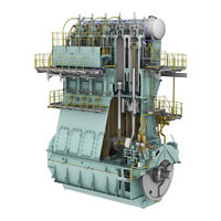
Sign In
Upload
Manuals
Brands
WinGD Manuals
Engine
X72DF
WinGD X72DF Manuals
Manuals and User Guides for WinGD X72DF. We have
2
WinGD X72DF manuals available for free PDF download: Maintenance Manual, Installation Manual
WinGD X72DF Maintenance Manual (902 pages)
Brand:
WinGD
| Category:
Engine
| Size: 58 MB
Table of Contents
Table of Contents
3
1 Introduction
22
Maintenance Manual - Change Record
22
Change Record
22
Preface
24
Technical Documentation Set
26
Technical Documentation Set
27
Data Module Codes (Procedural Data)
28
Data Module Codes (Procedural Data)
29
Data Module Codes (Descriptive Data)
30
Data Module Codes (Illustrated Parts Data)
32
About this Book
34
About the Engine
36
Group 1 - Engine Frame and Bearings
36
Group 2 - Cylinder
36
Group 3 - Crankshaft, Connecting Rod and Piston
36
Group 4 - Supply Unit Drive and Control
36
Group 5 - Supply Unit, Pumps and Control Valves
36
Group 6 - Scavenge Air Components
36
Group 7 - Cylinder Lubrication and Balancer
36
Group 8 - Pipes
36
Group 9 - Monitoring Instruments
36
Side View (Generic)
37
End View (Generic, Seen from the Driving End)
38
Engine Numbering (Generic)
40
List of Abbreviations
42
List of Abbreviations and Acronyms
42
2 Safety
47
Safety Precautions and Safety Rules
48
Safety Precautions and Safety Rules for Natural Gas
52
3 General Data for Maintenance
55
Lifting Tools
56
Lifting Capacities (for Information Only)
57
RUD-Eye Bolts
57
RUD-Swivel Lugs
59
Jointing Compounds
60
Jointing Compound
60
Clearances - General
62
Clearances
64
Crankshaft and Thrust Bearing - Clearances
64
Crankshaft and Thrust Bearing
64
Crankshaft and Main Bearings
65
Crosshead Guide
67
Cylinder Liner
68
Piston Rod Gland
69
Exhaust Valve - Spindle and Guide Bush
70
Exhaust Valve
70
Connecting Rod - Top and Bottom End Bearings
71
Piston and Piston Rings
72
Clearances - Piston Rings
72
Supply Unit - Drive Wheels
74
Fuel and Servo Pump Units
76
Clearances - Fuel and Servo Pump Units
76
Fuel Pump
78
Fuel Pump
79
Integrated Electric Balancer
80
Clearances - ELBA
80
Torque Values - Standard Screws
82
Torque Value - Applicable Decrease
82
4 General Mainteance Procedures
85
Do Maintenance Work - General Procedure
86
Tighten a Round Nut with a Pre-Tensioner
88
Loosen a Round Nut with a Pre-Tensioner
92
Do a Check of the Pre-Tension
96
5 Maintenance Schedule
99
Maintenance Schedule
100
6 Group 1 - Engine Frame and Bearings
101
Bedplate
102
Bedplate - Do a Check of the Foundation Bolts
102
Foundation Bolts
103
Main Bearing
104
Main Bearing - Remove the Cover
104
Main Bearing Cover (Example)
105
Thrust Device
106
Bearing Cover
107
Bearing Cover - Move
108
Main Bearing - Install the Cover
110
Thrust Device
111
Bearing Cover - Install
112
Bearing - Remove
113
Bearing Cover - Oil Pipe
114
Main Bearing Shell - Remove
116
Main Bearing Shell
116
Crankshaft and Flywheel - Lift
119
Bearing Shell - Remove
120
Bearing Shell - Lift
121
Main Bearing Shell - Examine
122
Main Bearing Shell - Install
124
Supports
124
Bearing Shell - Install
129
Thrust Bearing
132
Thrust Bearing - Examine the Housing
132
Visual Examination
133
Thrust Bearing - Do a Check of the Axial Clearance with a Dial Gauge
134
Axial Clearance
135
Thrust Bearing - Do a Check of the Axial Clearance with a Inside Micrometer
136
Axial Clearance - Micrometer
137
Thrust Bearing - Remove the Pads
140
Cover - Remove
141
Thrust Pad - Removal
143
Thrust Bearing - Install the Pads
146
Thrust Pad - Install
148
Thrust Pads - Configuration
149
Cover - Install
150
Engine Stays
152
Engine Stays (Friction Shims) - Do a Check of the Pre-Tension
152
Engine Stays (Hydraulic) - Do a Check of the Oil Pressure
154
Engine Stays - Pressure Check
155
Tie Rod
156
Tie Rod - Do a Check of the Pre-Tension
156
Pre-Tension Checks
157
Tie Rod - Remove
158
Tie Rod - Removal
159
Tie Rod - Install
160
Tie Rod - Apply Tension
162
7 Group 2 - Cylinder
163
Cylinder Liner
166
Cylinder Liner - Do a Check of the Bore
166
Cylinder Liner - Dimension Check
169
Cylinder Liner - Remove
172
Water Guide Jacket
174
Cylinder Liner (Example) - Move
176
Cylinder Liner - Preserve
178
Cylinder Liner - Storage
179
Cylinder Liner - Grind
182
Cylinder Liner - Grind the Lubricating Groove
184
Lubricating Grooves - Grind
185
Cylinder Liner - Grind the Scavenge Ports
186
Scavenge Ports - Grind
187
Cylinder Liner - Install
188
Insulation Bandage
189
Lubricating Quill
194
Lubricating Quill - Remove
194
Lubricating Quill - Do a Functional Test
196
Lubricating Quill - Install
198
Sealing Surface
199
Gas Admission Valve
202
Gas Admission Valve - Do a Check of the Oil Leakage Flow
202
GAV - Do a Check of the Oil Leakage Flow
203
GAV - Usual Values of Oil Leakage Flow at 25°C
204
Gas Admission Valve - Remove
206
Compensator - Remove
207
Gas Admission Valve - Do a Check for Gas Leakage
210
Gas Admission Valve - Pressure Check
211
Valve Seat - Lap
212
Gas Admission Valve - Disassemble
214
Valve Spindle - Remove
216
Gas Admission Valve - Assemble
218
GAV - Assemble
219
Gas Admission Valve - Install
220
Electrical Connection
222
Compensator - Install
223
Piston Rod Gland
224
Piston Rod Gland - Remove
224
Piston Rod Gland - Remove and Install
225
Piston Rod Gland - Disassemble
226
Piston Rod Gland - Do a Check of the Wear
228
Piston Rod Gland - Install
230
Piston Rod Gland - Assemble
232
Cylinder Cover
234
Cylinder Cover - Remove
234
Cylinder Cover - Pipes and Expansion Piece (Example)
236
Lifting Tool - Pre-Tensioner (Example)
237
Cylinder Cover, Exhaust Valve Cage and Water Guide Jacket (Example)
238
Cylinder Cover and Exhaust Valve Cage (Example)
239
Cylinder Cover - Grind the Sealing Face for Injection Valve
240
Fuel Injection Valve Position - Grind
242
Cylinder Cover - Grind the Sealing Face for Pilot Injection Valve
244
Grind the Sealing Face for Pilot Injection Valve
246
Cylinder Cover - Grind the Sealing Face for Prechamber
248
Grind the Sealing Face for Prechamber
249
Cylinder Cover - Install
252
Assemble before Installation (Example)
254
Direct Controlled Injection Valve
258
Direct Controlled Injection Valve - Remove
258
Direct Controlled Injection Valve - Do a Functional Test
260
Test Bench (Example)
261
Direct Controlled Injection Valve - Disassemble
264
Nozzle Tip - Remove
265
Direct Controlled Injection Valve - Assemble
268
Direct Controlled Injection Valve - Install
270
Starting Air Valve
272
Starting Air Valve - Remove the Solenoid Valve
272
Starting Air Valve - Remove
274
Starting Air Valve - Preparation
275
Starting Air Valve - Disassemble
278
Starting Air Valve - Grind
280
Starting Air Valve - Assemble
282
Starting Air Valve - Install
284
Starting Air Valve - Install the Solenoid Valve
286
Relief Valve Combustion Chamber
288
Relief Valve Combustion Chamber - Remove
288
Relief Valve
288
Relief Valve Combustion Chamber - Install
290
7.8.1 Relief Valve Combustion Chamber
290
Exhaust Valve
292
Exhaust Valve - Remove
292
Exhaust Valve - Preparation
293
Exhaust Valve - Removal
294
Exhaust Valve - Disassemble
296
Guide Bush - Removal
299
Exhaust Valve - Remove the Seat (with New Tool)
300
Valve Seat - Remove
301
Exhaust Valve - Do a Check of the Seat
304
Exhaust Valve, Clearance
305
Valve Seat Clearance
306
Exhaust Valve - Grind the Seat
308
Valve Seat - Grinding Tool
309
Exhaust Valve - Install the Seat (with New Tool)
310
Valve Seat - Install
312
Exhaust Valve - Assemble
314
Guide Bush - Installation
315
Valve Spindle - Installation
317
Damper Settings
318
Damper Setting (Example)
318
Valve Stroke Sensor, Throttle and Non-Return Valve
319
Exhaust Valve - Install
322
Exhaust Valve - Installation
323
Expansion Piece - Installation
324
Exhaust Valve - Complete the Installation
325
Pilot Injection Valve
326
Pilot Injection Valve - Remove
326
Pilot Injection Valve - Remove
328
Pilot Injection Valve - Remove the Injection Module
330
Pilot Fuel Valve - Remove the Injection Module
331
Pilot Injection Valve - Install the Injection Module
332
Pilot Fuel Valve - Install the Injection Module
333
Pilot Fuel Valve - Install the Nozzle Nut
334
Pilot Injection Valve - Do a Functional Test
336
Pilot Injection Valve - Checks
339
Pilot Injection Valve - Remove the Pre-Chamber
340
Pilot Injection Valve - Install the Pre-Chamber
342
Pilot Injection Valve - Install
344
Pilot Injection Valve
344
Seal - Install
345
8 Group 3 - Crankshaft, Connecting Rod and Piston
349
Crankshaft
350
Crankshaft - Do a Check of the Crank Deflection
350
Dial Gauge Position
351
Crank Positions for Clockwise Direction
352
Connecting Rod
352
Maximum Permitted Difference in MM
353
Definitions of Positions
353
Crank-Web Deflection Limits in MM
354
Definition of Deflection
355
Crankshaft - Install the Work Platform
356
Crankshaft - Remove the Work Platform
358
Torsional Vibration Damper
360
Torsional Vibration Damper - Examine
360
Axial Vibration Damper
362
Axial Vibration Damper - Disassemble
362
Axial Vibration Damper - Housing and Pipes
363
Axial Vibration Damper - Move
365
Axial Vibration Damper - Assemble
366
Axial Vibration Damper - Install
368
Axial Vibration Damper - Bolts
369
Turning Gear
372
Turning Gear - Do a Check of the Screwed Connections
372
Turning Gear - Do a Check
372
Turning Gear - Lubricate the Teeth
374
Turning Gear and Gear Wheels
375
Recommended Suppliers
376
Connecting Rod
378
Connecting Rod - Prepare before Removal
378
Stop Plate
378
Connecting Rod - Remove
382
Connecting Rod - Move
385
Connecting Rod - Move 2
389
Connecting Rod - Remove the Top End Bearing Cover
392
Equipment - Install
395
Top Bearing Cover - Removal
396
Connecting Rod - Remove the Top End Bearing
398
Top End Bearing - Remove
399
Connecting Rod - Remove the Bottom End Bearing
400
Bottom End Bearing Cover - Move
402
Bottom End Bearing Shell - Remove
403
Bottom End Bearing
405
Top Bearing Shell - Remove
406
Connecting Rod - Examine the Bearing Shells
408
Connecting Rod - Install the Bottom End Bearing
410
Top Bearing Shell - Move
413
Bottom End Bearing
414
ISO VG 1000/1500 Suppliers
415
Bottom End Bearing - Install
417
ISO VG 1000/1500 Suppliers
418
Connecting Rod - Install the Top End Bearing
420
Top End Bearing - Move
422
Crosshead - Lower
423
Bearing Lubrication
424
Connecting Rod - Install the Top End Bearing Cover
426
Top Bearing Cover - Move
427
Top Bearing Cover - Install
429
Connecting Rod - Install
432
Crosshead - Install
440
Toggle Lever - Attach
441
Piston - Attach
442
Crosshead - Remove
444
Crosshead
444
Toggle Lever - Remove
446
Crosshead Bearing - Temperature Sensor
447
Tools - Prepare
448
Bracket - Attach
449
Tools - Attach
450
Connecting Rod - Move
451
Crosshead - Move
452
Crosshead - Remove
453
Crosshead - Remove
455
Guide Shoes - Remove
456
Crosshead - Do a Check of the Clearances
458
Clearance Checks
459
Dimensions Check
460
Crosshead - Install
462
Guide Shoe - Move
464
Guide Shoes - Install
466
Connecting Rod - Move
468
Tools - Remove
469
Piston
472
Piston (Installed) - Do Checks of the Surface and Clearances
472
Top Surface - Dimensions Check
473
Piston Ring - Clearance
474
Piston - Prepare before Removal
476
Piston - Preparation
477
Piston - Preparation before Removal (Example)
479
Piston - Remove
482
Piston - Disassemble
486
Piston - Preparation before Disassembly
487
Piston (Removed) - Do Checks of the Surface and Clearances
490
Piston Groove Clearance - Calliper Gauge
491
Piston - Assemble
494
Torque Values
495
Piston - Install
498
Piston - Move (Example)
499
Piston Rod Gland - Attach (Example)
501
Piston Ring
504
Piston Ring - Remove
504
Piston Ring - Remove (Example)
505
Piston Ring - Install
506
Piston Rings - Install (Example)
507
9 Group 4 - Supply Unit Drive and Control Components
509
Shut-Off Valve for Starting Air - Disassemble
509
Driving Wheel
510
Gear Wheel Crankshaft - Examine the Teeth
510
Gear Wheel Crankshaft - Do a Check of the Teeth Backlash
512
Driving Wheel - Gear Tooth Backlash
514
Shut-Off Valve for Starting Air
516
Shut-Off Valve for Starting Air - Disassemble
516
Shut-Off Valve for Starting Air - Prepare for Disassembly
517
Shut-Off Valve for Starting Air - Assemble
522
Shut-Off Valve for Starting Air - Do a Test of the Operation
526
Shut-Off Valve for Starting Air - Operation Test
528
10 Group 5 - Supply Unit, Pumps and Control Valves
529
Servo Oil Pump
530
Servo Oil Pump - Do a Check for Wear and Damage
530
Servo Oil Pump - Remove
532
Servo Oil Pump - Install
536
Supply Unit for Pilot Fuel
540
Supply Unit for Pilot Fuel - Remove the Pump
540
Supply Unit for Pilot Fuel - Tool
542
Supply Unit for Pilot Fuel - Lubricate the Coupling
544
Pilot Fuel Supply Unit
545
Supply Unit for Pilot Fuel - Install the Pump
546
Pilot Fuel Supply Unit - Install
547
Pilot Fuel Supply Unit - Clearances
548
Pilot Fuel Supply Unit - Completion
549
Fuel Pump
550
Fuel Pump - Remove
550
Fuel Pump - Disassemble
554
Guide Pin Removal
555
Guide Piston and Roller Removal
556
Toothed Rack Removal
557
Pump Cylinder Removal
558
Non-Return Valve Removal
559
Fuel Pump - Assemble
560
Pump Cylinder Installation
561
Pump Cover Installation
562
Toothed Rack Assembly
563
Pump Plunger and Bottom Housing Assembly
564
Plunger Position Check
565
Fuel Pump - Install
568
Fuel Pump Installation
569
Fuel Pump - Do a Test of the Operation
572
Fuel Pump - Oil Flow
573
Fuel Pump Actuator
576
Fuel Pump Actuator - Calibrate
576
Calibration Illustration
577
Fuel Pump Actuator - Adjust
580
Actuator - Adjust
581
Actuator - Adjust -2
582
Fuel Pressure Control Valve
584
Fuel Rail - Remove the Pressure Control Valve
584
Pressure Control Valve - Remove
585
Fuel Rail - Do a Check of the Pressure Control Valve
586
PCV - Do a Check
587
Fuel Rail - Install the Pressure Control Valve
590
Pressure Control Valve - Install
591
Fuel Overpressure Safety Valve
592
Fuel Rail - Remove the Overpressure Safety Valve
592
Fuel Rail - Do a Check of the Overpressure Safety Valve
594
Fuel Overpressure Safety Valve - Pressure Check
596
Fuel Rail - Install the Overpressure Safety Valve
598
Fuel Overpressure Safety Valve - Installation
599
Flow Limiting Valve
600
Flow Limiting Valve - Do an Inspection
600
Flow Limiting Valve - Inspection
601
Flow Limiting Valve - Remove
604
Flow Limiting Valve - Install
608
Flow Limiting Valve - Install the Flange
609
Flow Limiting Valve and Fuel Rail
611
Exhaust Valve Control Unit
612
Exhaust Valve Control Unit (VCU) - Remove
612
Exhaust Valve Control Unit - Remove
613
Exhaust Valve Control Unit (VCU) - Disassemble
614
Exhaust Valve Control Unit - Disassemble/Assemble
615
Exhaust Valve Control Unit (VCU) - Assemble
616
Exhaust Valve Control Unit (VCU) - Install
618
Exhaust Valve Control Unit - Install
619
Distance X for VCU
620
Connection Piece of VCU
620
11 Group 6 - Scavenge Air Components
623
Scavenge Air Receiver
624
Scavenge Air Receiver - Examine
624
Scavenge Air Receiver - Visual Examination
626
Level Switches and Filters
627
Scavenge Air Receiver - Do a Check of the Relief Valve
628
Scavenge Air Receiver - Remove the Flaps
630
Flaps - Remove
631
Scavenge Air Receiver - Install the Flaps
632
Flaps - Install
633
Auxiliary Blower
634
Auxiliary Blower - Remove
634
Electric Motor (Driving End) - Move
635
Electric Motor (Driving End) - Remove
636
Electric Motor (Free End) - Move
637
Auxiliary Blower - Install
640
Auxiliary Blower - Move
642
Electric Motor (Free End) - Install
643
Auxiliary Blower (Driving End) Move
644
Electric Motor (Driving End) - Install
645
Scavenge Air Cooler
646
Scavenge Air Cooler - Remove
646
Scavenge Air Cooler (Example) - Prepare
648
Scavenge Air Cooler - Install
654
Scavenge Air Cooler (Example) - Prepare for Installation
656
Scavenge Air Cooler (Example) - Follow up Front and Rear Side
657
Water Separator
658
Water Separator - Remove
658
Water Separator - View 1
659
Water Separator - View 2
660
Water Separator - View 3
661
Water Separator - View 4
662
Water Separator - View 5
663
Water Separator - Install
664
Water Separator - View 6
665
Water Separator - View 7
666
12 Group 7 - Cylinder Lubrication and Balancer
669
Cylinder Lubricating Pump (MK-E)
669
Cylinder Lubrication System
670
Cylinder Lubrication System - Do a Functional Test
670
Cylinder Lubrication System - Bleed
672
Cylinder Lubricating Pump - Remove
676
Cylinder Lubricating Pump (MK-1) - Examine
680
Cylinder Lubricating Pump (MK-E) - Do a Service
682
Cylinder Lubricating Pump - Install
686
Integrated Electric Balancer (Ielba)
688
Integrated Electric Balancer - Prepare before the Bearings Removal
688
Integrated Electric Balancer
688
Integrated Electric Balancer - Remove the Bearing (Engine Side)
690
Counterweights - Lock
691
Bearing - Remove
692
Integrated Electric Balancer - Remove the Bearing (Outer Side)
694
Outer Bearing - Remove
696
Integrated Electric Balancer - Do a Check of the Bearing Clearance
698
Integrated Electric Balancer
698
Integrated Electric Balancer - Adjust
699
Integrated Electric Balancer - Adjust the Bearings
702
Electric Balancer - Adjust Bearings
703
Electric Balancer Sensor Unit - Remove the Proximity Sensor
706
Proximity Sensor - Remove
707
Electric Balancer Sensor Unit - Install the Proximity Sensor
708
Proximity Sensor - Install
709
Integrated Electric Balancer - Do a Check of the Backlash
710
Integrated Electric Balancer - Backlash
711
Integrated Electric Balancer - Install the Bearing (Engine Side)
714
Bearing - Install
715
Integrated Electric Balancer - Install the Bearing (Outer Side)
716
Outer Bearing - Install
717
13 Group 8 - Pipes
719
HP Servo Oil Pipe
720
HP Servo Oil Pipe - Remove
720
Servo Oil Pipes - Remove
722
HP Servo Oil Pipe - Grind the Sealing Face
724
Distance X for HP Servo Oil Pipe
725
HP Servo Oil Pipe - Grind and Adjust
726
HP Servo Oil Pipe - Install
728
Servo Oil Pipes - Install
730
Hydraulic Pipe Exhaust Valve
732
Hydraulic Pipe Exhaust Valve - Remove
732
Hydraulic Pipe (Exhaust Valve) - Remove
734
Hydraulic Pipe Exhaust Valve - Grind the Sealing Face
736
Hydraulic Pipe (Exhaust Valve) - Grind Sealing Face
738
Hydraulic Pipe Exhaust Valve - Install
740
Hydraulic Pipe (Exhaust Valve) - Install
740
Distance X for Hydraulic Pipe Exhaust Valve
741
HP Fuel Pipe
744
HP Fuel Pipe (Fuel Rail to Injection Valve) - Prepare before Removal
744
HP Fuel Pipe - Preparation
745
HP Fuel Pipe (Fuel Rail to Injection Valve) - Remove
746
HP Fuel Pipe - Removal
747
HP Fuel Pipe (Fuel Rail to Injection Valve) - Grind the Sealing Face
748
HP Fuel Pipe - Grind
749
HP Fuel Pipe (Fuel Rail to Injection Valve) - Install
752
Distances X and y for HP Fuel Pipe
753
HP Fuel Pipe - Install
754
HP Fuel Pipe - Completion
755
HP Fuel Pipe (Fuel Pump to Fuel Rail) - Prepare before Removal
756
HP Fuel Pipe (Fuel Pump to Fuel Rail) - Remove
758
HP Fuel Pipes - Remove and Install
759
HP Fuel Pipe (Fuel Pump to Fuel Rail) - Grind the Sealing Face
760
HP Fuel Pipe (Fuel Pump to Fuel Rail) - Install
764
Distance X for HP Fuel Pipe
765
HP Fuel Pipes - Adjust
766
HP Pilot Fuel Pipe
768
HP Pilot Fuel Pipe - Remove
768
Pilot Fuel Pipe - Remove
770
HP Pilot Fuel Pipe - Install
772
Distance X for Pilot Fuel Pipe
773
Pilot Fuel Pipe- Prepare
774
Pilot Fuel Pipe - Install
775
Advertisement
WinGD X72DF Installation Manual (237 pages)
Brand:
WinGD
| Category:
Engine
| Size: 7 MB
Table of Contents
List of Changes
3
Table of Contents
9
Preface
22
Marine Installation Manual Introduction
22
Explanation of Symbols in this Marine Installation Manual
23
Marine Installation Drawing Set
24
General Technical Data (GTD)
25
Operation and Maintenance Manuals
25
GTD Screenshot
25
Engine Summary
26
Engine Capability and Features
26
X72DF Summary Values for Maximum Continuous Rating (MCR)
26
Special Engine Features
27
Principal Engine Features and Technologies
27
Primary Engine Data
28
Power /Speed Range of the Wingd X-DF Engines
28
Engine Rating Field - Rating Points
29
Rating Points
29
System
29
Principal Engine Dimensions and Weights
30
Principal Engine Dimension Values
30
Principal Engine Dimensions
30
Fuel Operating Modes
31
Fuel Split (Energy-Based) for Different Operating Modes
31
Operating Modes of the X-DF Engine
31
Operation in Gas Mode
32
Dynamic Combustion Control
32
Gas Mode Operation
32
Power Meter Requirement
33
Operation in Diesel Mode
33
Power Meter Parameters
33
The Flex System
34
The Flex System Parts
34
Operation in Fuel Sharing Mode
35
Fuel Sharing Mode - Available Operating Window
35
Fuel Sharing Mode - Energy Amount of Different Ratios of Fuel
36
Changeover between Operating Modes
37
Transfers and Gas Trips
37
Fuel Transfers and Gas Trips
37
Engine Power and Speed
39
Introduction to Power and Speed
39
Engine Rating Field
39
Rating Field for the X72DF
39
Rating Points
40
Influence of Propeller Diameter and Revolutions
40
Power Range
41
Propeller Curves and Operational Points
41
Sea Trial Power
42
Sea Margin
42
Propeller Curves and Operational Points
42
Light Running Margin
43
Continuous Service Rating
43
Engine Margin
43
Contracted Maximum Continuous Rating
43
Power Range Limits
44
Line 5 Coefficients
46
Line 6 Coefficients
46
Power Range Limits with a Power Take-Off Installation for a FPP
48
PTO Incorporation of Method 1
48
Power Range Diagram of an Engine with a PTO
48
Line 10 Coefficients
49
PTO Incorporation of Method 2
50
Power Range Limits
50
Prohibited Operation Area
51
The Prohibited Operation Area (CMCR Speed = R1-R2)
51
Prohibited Operation Area for Different Speed Rated Engines
53
Calculating the Prohibited Operation Area for the CMCR Speed
53
CPP Requirements for the Propulsion Control System
56
Engine Installation
57
Engine Dimensions and Masses
57
Engine Dimensions
57
Dismantling Heights for Piston and Cylinder Liner
58
Crane Requirements
58
Thermal Expansion between the Turbocharger and Exhaust Gas
59
Piping
59
Thermal Expansion, DIM. X, Y, Z
59
Content of Fluids in the Engine
60
Conditions and Requirements
61
Pressure and Temperature Ranges
61
Operating Conditions
61
Reference Conditions
61
Design Conditions
61
Ancillary System Design Parameters
62
Electrical Power Requirement
63
Engine Outline Views
64
Platform Arrangement
65
Drawings
65
Minimum Requirements for Escape Routes
65
Minimum Requirements for Headroom
65
Seating
66
Assembly
67
Assembly of Subassemblies
67
Installation of a Complete Engine
68
Installation of an Engine from Assembled Subassemblies
68
Installation of an Engine in Ship on Slipway
68
Engine and Shaft Alignment
69
Instructions and Limits
69
Tools
69
Engine Coupling
70
Design
70
Machining and Fitting of Coupling Bolts
70
Tightening
70
Installation Drawing
70
Engine Stays
71
Propulsion Shaft Earthing
72
Preventive Action
72
Earthing Device
72
Typical Shaft Earthing Arrangement
73
Typical Shaft Earthing with Condition Monitoring Facility
74
Fire Protection
75
Recommended Quantities of Fire Extinguishing Medium
75
Ancillary Systems
76
Twin-Engine Installation
77
Common and Independent Systems in Twin-Engine Installations
77
Fuel Oil System
77
System
77
Cooling Water System for Twin-Engine Installation
78
Cooling Water System
79
Separate HT Cooling Water Circuit
79
Low-Temperature Circuit
80
Arrangement 1
81
Arrangement 2
81
LT Cooling Water Circuit - Single Set-Point Temperature
81
LT Cooling Water Circuit - Dual Set-Point Temperatures
81
Arrangement 3
82
Separate SAC and LT Cooling Circuits
82
Low-Temperature Circuit Components
83
High-Temperature Circuit
84
High-Temperature Circuit Components
85
HT Cooling Water Circuit
85
Pre-Heating
88
Pre-Heating from Cooling Water Systems
88
Pre-Heating by Direct Water Circulation
88
Freshwater Generator
89
Pre-Heating Power Requirement Per Cylinder
89
Cooling Water Treatment
90
Recommended Specifications for Raw Water
90
General Recommendations for the Cooling Water System Design
91
Lubricating Oil Systems
92
Lubricating Oil Requirements
92
Main Lubricating Oil System
92
Lubricating Oil System
92
Main Lubricating Oil System Components
93
System Oil
95
Flushing the Lubricating Oil System
95
Lubrication for Turbochargers
95
Cylinder Lubricating Oil System
95
Changeover between Cylinder Lubricating Oils
96
The Icat Changeover Unit
97
Dual Cylinder Lubricating Oil Installation with Icat as an Optional
97
Dual Cylinder Lubricating Oil Installation Without Icat, Enabling
98
Service Tank and Storage Tank
99
Cylinder Lubricating Oil System for Fuel with Ultra Low Sulphur
99
Electrical Trace Heating for System Side Cylinder Lubricating Oil
100
Heating Cable Specification
100
Maintenance and Treatment of Lubricating Oil
102
Drain Tank
103
Arrangement of Vertical Lubricating Oil Drains for 6-Cylinder Engines
104
Fuel Gas System
108
Safety Considerations
108
Operating Principles
109
The Lean-Burn Concept
109
Gas Specifications
111
Methane Number Dependent Engine Output
112
Methane Number Calculation
112
Fuel Gas Supply System
113
Master Fuel Gas Engine Shut-Off Valve
113
Tank Type
113
Section View of an Integrated Membrane Tank
114
Section View of a Free-Standing Type a Tank
114
Section View of a Free-Standing Type B Tank of Moss Design
115
Supplying Fuel Gas
117
Pressurised Type C Tank Solution with NBOG Handling by the
118
Pressurised Type C Tank Solution with NBOG Handling by the
119
Non-Pressurised Tank Solution, Drawn for an LNGC
119
Re-Liquefaction Process
120
Fuel Gas Supply Pressure
122
Design Fuel Gas Supply Pressure Requirements
123
Fuel Gas Supply Pressure Control at the Engine Inlet
125
Fuel Gas Supply Pressure Control at the GVU Inlet
126
Fuel Gas Pressure Level Definitions
126
On-Engine Integrated Gas Pressure Regulation Unit
127
Fuel Gas Supply System with the Igpr
127
Off-Engine Gas Valve Unit
129
Fuel Gas Venting
131
Ventilation of Double-Wall Fuel Gas Piping
131
Purging by Inert Gas
132
Purity of Inert Gas (Engines with Igpr)
133
Purity of Inert Gas (Engines with GVU)
133
Fuel Gas Leak Test
135
Gas Leak Test Sequence (Engines with Igpr)
135
Gas Leak Test Sequence (Engines with GVU)
135
Pilot Fuel Oil System
136
Specification of the Pilot Fuel Oil Filter on the System Side
138
Fuel Oil System
139
Fuel Oil System Components
139
Feed Pump - Low-Pressure Fuel Oil
140
Pressure Regulating Valve
141
Mixing Unit
141
Mixing Unit
142
Booster Pump - High-Pressure Fuel Oil
143
End-Heater
143
Viscometer
144
MDO/MGO Heat Exchanger
144
Fuel Oil Filters - Arrangement 'A
145
Fuel Oil Filter Arrangement 'A
146
Specification of Automatic Self-Cleaning Filter in Feed System
147
Specification of Automatic Self-Cleaning Filter in Booster System
148
Specification of Duplex Filter in Booster System
149
Fuel Oil Filter - Arrangement 'B
150
Fuel Oil Filter Arrangement 'B
150
Fuel Oil System with Only MDO/MGO or MGO
151
Fuel Oil Feed Pump
152
Fuel Oil Heat Exchanger
152
Fuel Oil Filter
152
Flushing the Fuel Oil System
152
Fuel Oil Treatment
153
Settling Tanks
153
Service Tanks
153
Centrifugal Fuel Oil Separators
153
Pressurised Fuel Oil System
155
Fuel Oil Specification
155
Fuel Oil Viscosity-Temperature Dependency
156
Fuel Oil Viscosity-Temperature Diagram
156
Air Supply System
157
Capacities of Air Compressor and Receiver
158
System Specification
158
Starting Air Compressors
158
Starting Air Receivers
158
Control Air
159
Service and Working Air
159
Leakage Collection System and Washing Devices
160
Sludge Oil Trap Solutions
160
General Description of the Sludge Oil Trap
160
Solution 1: a Constantly-Drained Sludge Oil Trap with Separate Sludge Accumulation
161
Solution 2: a Manually Bottom-Drained Sludge Oil Trap
162
Design Proposal of Wingd's Sludge Oil Trap
162
Design Proposal of a Manually Bottom-Drained Sludge Oil Trap
163
Solution 3: an Automatically Bottom-Drained Sludge Oil Trap
164
Design Proposal of an Automatically Bottom-Drained Sludge Oil Trap
165
Draining of Exhaust Uptakes
166
Air Vents
166
Exhaust Gas System
167
Engine Room Ventilation
168
Ventilation Requirements
168
Ventilation Arrangement
169
Arrangement 1 - Engine Room Ventilation System
169
Arrangement 2 - Direct Engine Ventilation System
169
Ventilation System Arrangement 1 - Engine Room Ventilation
170
Ventilation System Arrangement 2 - Direct Engine Ventilation
171
Air Intake Quality
172
Outside Ambient Air Temperature
174
Operational Temperature Range Requirements of the Turbocharger
174
Piping
175
Pipe Connections
175
Flow Rates and Velocities
175
PTO, PTI, PTH and Primary Generator Applications
176
Requirements
176
Arrangements for PTO, PTI, PTH and Primary Generator
176
Arrangements for PTO, PTI, PTH
177
Application Constraints
178
Service Conditions
180
Engine Automation
183
Denis
183
Engine Automation Architecture
183
DENIS Concept
184
Interface Definition
184
Approved Propulsion Control Systems
184
Engine Management and Automation Concept
184
DENIS Specification
185
DENIS Interface Specification
185
DENIS Propulsion Control Specification
185
Propulsion Control Systems
186
Suppliers of Remote Control Systems
186
Remote Control System
186
Functions of the Propulsion Control System
188
Remote Control System
188
Safety System
188
Telegraph System
188
Local Manual Control
188
ECR Manual Control Panel
188
Options
189
Propulsion Control
189
Recommended Manoeuvring Characteristics
190
Recommended Manoeuvring Steps and Warm-Up Times for FPP
191
Full Sea Load Steps in FPP Load-Up Program
191
Recommended Manoeuvring Steps and Warm-Up Times for CPP
192
Full Sea Load Steps in CPP Load-Up Program
192
Alarm and Monitoring System
193
Integrated Solution
193
Split Solution
193
Alarm Sensors and Safety Functions
194
Signal Processing
194
Requirements of Wingd and Classification Societies
194
Additional Class Requirements for Alarm Sensors and Safety
194
Wingd Integrated Digital Expert
195
Data Collection and Monitoring
195
The Wide System
195
Engine Diagnostic System
196
Wide Installation Process
197
The Wide Installation Process Map
197
Engine Dynamics
198
External Mass Forces and Moments
199
Balancing of Mass Forces and Moments
199
Countermeasures for Second Order Vertical Mass Moments
200
Integrated Electrical Balancer (Ielba)
200
Major Components and Details of the Ielba
200
Electrically-Driven Compensator (External Compensator)
201
Locating an Electrically-Driven Compensator
201
Power Related Unbalance
202
External Lateral Forces and Moments
203
Forces through the Engine
203
Lateral Vibration Types
204
H-Type Vibration
204
X-Type Vibration
204
Lateral Vibration - X-Type and H-Type
204
Reduction of Lateral Vibration
205
Lateral Hydraulic Type Stays
205
General Arrangement of Hydraulic Type Stays for One-Side
205
Electrically-Driven Compensator
206
General Arrangement of Hydraulic Type Stays for Both-Side
206
Longitudinal Vibration (Pitching)
207
Reduction of Longitudinal Vibration (5-Cylinder Engines)
207
Arrangement of Longitudinal Stays
207
Torsional Vibration
209
Reduction of Torsional Vibration
209
Low-Energy Vibrations
210
High-Energy Vibrations
210
PTO/PTI Systems Effect on Torsional Vibration
211
Vibration Dampers (Spring Type and Viscous Type)
211
Axial Vibration
212
Reduction of Axial Vibration
212
Whirling Vibration
213
Hull Vibration
214
Countermeasures for Dynamic Effects
215
External Mass Moments and Vibrations
215
Countermeasures for External Mass Moments
215
Countermeasures for Lateral and Longitudinal Vibrations
215
Countermeasures for Torsional and Axial Vibrations of the Shafting
215
Synchro-Phasing System in Twin Engines
216
Concept
216
Resulting Vibration from SPS Combinations
216
Components and Control
217
Synchro-Phasing System
217
Operating Modes and Restrictions
218
Order Forms for Vibration Calculation & Simulation
219
Engine Emissions
220
Exhaust Gas Emissions
220
Selective Catalytic Reduction
221
Low-Pressure SCR
221
Low-Pressure SCR - Arrangement
221
High-Pressure SCR
222
High-Pressure SCR - Arrangement
222
Engine Noise
223
Air-Borne Noise
223
Exhaust Noise
225
Exhaust Noise Reference Point
225
Sound Pressure Level at Funnel Top of Exhaust Gas System
226
Structure-Borne Noise
227
Structure-Borne Noise Level at Engine Feet Vertical
227
Advertisement
Related Products
WinGD X72
WinGD X82-B
WinGD X92DF
WinGD X62DF
WinGD X72-B
WinGD X35-B
WinGD X92-B
WinGD X92
WinGD X62DF-S2.0
WinGD W-X82
WinGD Categories
Engine
Marine Equipment
Industrial Equipment
More WinGD Manuals
Login
Sign In
OR
Sign in with Facebook
Sign in with Google
Upload manual
Upload from disk
Upload from URL