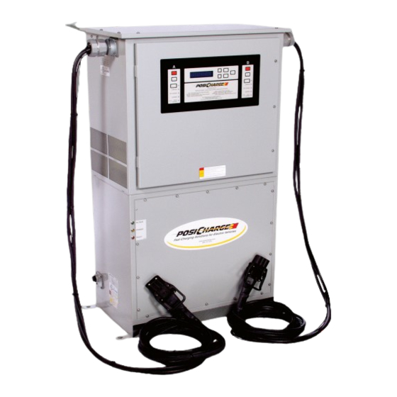
Sign In
Upload
Manuals
Brands
Webasto Manuals
Battery Charger
PosiCharge DVS
Webasto PosiCharge DVS Manuals
Manuals and User Guides for Webasto PosiCharge DVS. We have
1
Webasto PosiCharge DVS manual available for free PDF download: Field Service Manual
Webasto PosiCharge DVS Field Service Manual (56 pages)
GSE
Brand:
Webasto
| Category:
Battery Charger
| Size: 10.9 MB
Table of Contents
Table of Contents
3
Symbol Usage
5
General Information
7
Scope
7
How to Use this Document
7
List of Terms and Acronyms
8
Applicable Documents
8
List of Equipment
9
System Overview
10
Figure 1. DVS Compartments
10
System Troubleshooting Guide
11
How to Use this Section
11
ESD Precautions
11
Problem Symptoms and Action Key
12
Table 1. Symptoms and Action Key
12
Fault Messages
14
Table 2 Fault Codes and Action Key
14
Actions
16
Charge Termination Codes
22
Table 3. Charge Termination Codes
22
Maintenance and Repair
23
Powerstation Cabinet
23
Equipment Access
23
Access to Front Enclosure
23
Access to Top Enclosure
23
Powerstation Periodic Maintenance
24
Field Application Software Upgrades
24
Application Software Upgrades
24
Field Replaceable Parts (Powerstation Cabinet)
24
Door Assembly (P/N 07308)
25
Cooling Fans (P/N 06903)
26
Power Supply (P/N 06860)
26
15V Power Supply (P/N 08340)
27
Power Stage Assembly (P/N 06906)
27
Power Terminal (P/N 05383)
27
Contactor (P/N 06902)
28
Inductor Thermal Switches (P/N 05162)
28
Control Board (P/N 08067)
29
Display Board (P/N 06457)
30
Current Sensors (P/N 05109)
30
Bmid
31
Locating the BMID
31
Basic Operation
31
Troubleshooting Guide
31
Replacing the BMID
32
Charging Cable and Data Wires
32
Inspecting Cables, Wires and Connectors
32
Power Supply Cabinet
33
Equipment Access
33
Figure 2. Cabling between Cabinets
33
Figure 3. Power Supply Cabinet Main Control Panel
34
Power Supply Cabinet Routine Maintenance
35
Figure 4. Power Supply Cabinet Status Indicator Lights
35
Measuring Line-To-Line Voltage
36
Table 4. Power Supply Cabinet Field Replaceable Parts
36
Removal, Test and Replacement of Fuses
37
Figure 5. Line-To-Line Test Points
37
Figure 6. Fuses F1, F2 and F3
37
Troubleshooting Main Contactor, K1
38
Figure 7. Main Contactor, K1
38
Diagnosing Root Cause for Red Fault Light Illumination
39
Troubleshooting Main 120VAC Circuit
39
Figure 8. Main 120VAC Transformer, T3
39
Troubleshooting Thermal Issues
40
Table 5. Transformer T3 Expected Voltages
40
Figure 9. Exhaust Fan Detail
41
Figure 10. De-Misting Balls
41
Testing Main Rectifier
42
Figure 11. Rectifier Connections to Transformer
42
3.4.10 Troubleshooting Pre -Charge Circuitry
43
3.4.11 Testing Relays K2 and K3
43
Figure 12. D1 DC Connections
43
Figure 13. Relays K2 and K3
44
Table 6. Relay System Test Points and Expected Values
45
3.4.12 Testing Rectifiers D2 and D3
46
Figure 14. Rectifiers D2, D3
46
Advertisement
Advertisement
Related Products
Webasto PosiCharge ProCore Series
Webasto PosiCharge ProCore
Webasto Pure
Webasto ProCore Edge
Webasto Pordoi 2000
Webasto Thermo Pro 50 Eco
Webasto Thermo Pro 90
Webasto Thermo Pro 90 12 V
Webasto ProMaster Ibiza
Webasto ProMaster Vancouver Standard
Webasto Categories
Heater
Water Heater
Automobile Accessories
Battery Charger
Air Conditioner
More Webasto Manuals
Login
Sign In
OR
Sign in with Facebook
Sign in with Google
Upload manual
Upload from disk
Upload from URL