Sign In
Upload
Manuals
Brands
WAGO Manuals
Adapter
750-325
WAGO 750-325 Manuals
Manuals and User Guides for WAGO 750-325. We have
1
WAGO 750-325 manual available for free PDF download: Manual
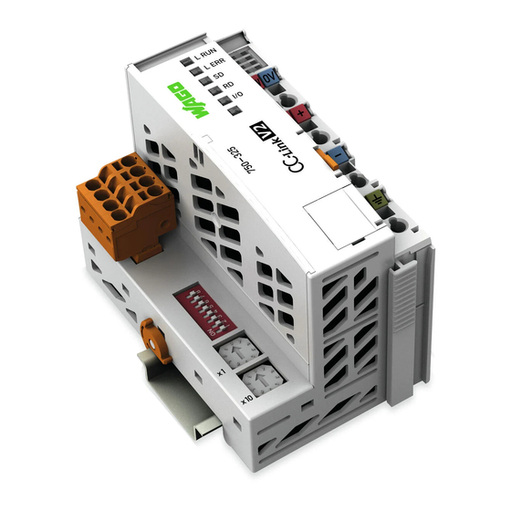
WAGO 750-325 Manual (180 pages)
CC-Link Fieldbus Couplerб 156 kBaud ... 10 MBaud; digital and analog signals
Brand:
WAGO
| Category:
Adapter
| Size: 8.35 MB
Table of Contents
Table 1: Number Notation
11
Table 2: Font Conventions
11
Figure 1: Fieldbus Node (Example)
17
Figure 2: Marking Area for Serial Numbers
18
Table 3: Legend for Figure "Update Matrix from 2016
19
Figure 3: Update Matrix up to 2015
19
Figure 4: Update Matrix from 2016
19
Figure 5: Isolation for Fieldbus Couplers/Controllers (Example)
22
Table 4: Legend for Figure "System Supply Via Fieldbus Coupler/Controller (Left) and Via Internal System Supply Module (Right)
23
Figure 6: System Supply Via Fieldbus Coupler/Controller (Left) and Via Internal
23
Figure 7: System Voltage for Standard Couplers/Controllers and Extended
24
Table 5: Alignment
25
Table 6: Legend for Figure "Field Supply for Standard Couplers/Controllers
28
Figure 8: Field Supply for Standard Couplers/Controllers and Extended ECO
28
Table 7: Power Supply Modules
30
Figure 9: Supply Module with Fuse Carrier (Example 750-610)
30
Figure 10: Removing the Fuse Carrier
31
Figure 11: Opening the Fuse Carrier and Changing the Fuse
31
Figure 12: Changing the Fuse and Closing the Fuse Carrier
32
Figure 13: Push Back the Fuse Carrier
32
Figure 14: Fuse Modules for Automotive Fuses, Series 282
33
Figure 15: Fuse Modules for Automotive Fuses, Series 2006
33
Figure 16: Fuse Modules with Pivotable Fuse Carrier, Series 281
33
Figure 17: Fuse Modules with Pivotable Fuse Carrier, Series 2002
34
Table 8: Filter Modules for 24 V Supply
35
Figure 18: Power Supply Concept
35
Figure 19: Supply Example for Standard Couplers/Controllers
36
Table 9: Legend for Figure "Supply Example for Fieldbus Coupler/Controller
37
Table 10: WAGO Ground Wire Terminals
39
Figure 20: Carrier Rail Contact (Example)
40
Figure 21: Cable Shield at Ground Potential
41
Figure 22: Examples of the WAGO Shield Connecting System
42
Figure 23: Application of the WAGO Shield Connecting System
42
Figure 24: View Fieldbus Coupler CC-Link V 2.0
44
Table 11: Legend for Figure "View Fieldbus Coupler CC-Link V2.0
45
Figure 25: Device Supply
46
Table 12: Signal Assignment for the CC-Link Fieldbus Connection
47
Figure 26: Fieldbus Connections, Series 231 (MCS)
47
Table 13: Display Elements Fieldbus Status
48
Table 14: Display Elements Node Status
48
Table 15: Display Elements Supply Voltage
48
Figure 27: Display Elements
48
Table 16: Legend for Figure "Service Interface (Closed and Opened Flap)
49
Figure 28: Service Interface (Closed and Opened Flap)
49
Figure 29: Rotary Encoder Switch Station Address
50
Table 17: Operation Mode Setting
51
Figure 30: DIP Switch
51
Table 18: Extended Cyclic Setting
52
Table 19: Occupied Stations Setting
52
Table 20: Baud Rate Setting
52
Table 21: Technical Data - Device Data
53
Table 22: Technical Data - System Data
53
Table 23: Technical Data - Supply
54
Table 24: Technical Data - Accessories
54
Table 25: Technical Data - Field Wiring
54
Table 26: Technical Data - Power Jumper Contacts
55
Table 27: Technical Data - Data Contacts
55
Table 28: Technical Data - Climatic Environmental Conditions
55
Table 29: Technical Data - Mechanical Strength
56
Table 30: WAGO DIN Rails
62
Figure 31: Spacing
62
Figure 32: Release Tab of Extended ECO Fieldbus Coupler (Example)
65
Figure 33: Inserting I/O Module (Example)
66
Figure 34: Snap the I/O Module into Place (Example)
66
Figure 35: Removing the I/O Module (Example)
67
Figure 36: Data Contacts
68
Figure 37: Example for the Arrangement of Power Contacts
69
Figure 38: Connecting a Conductor to a CAGE CLAMP
70
Figure 39: Initialization
71
Table 31: Assigned Areas Depending in the CC-Link Configuration Setting
73
Table 32: Data Area of the Remote I/Os (Example V1.1 and V2.0 at the Setting of One Cycle)
75
Table 33: System Area Flags
76
Table 34: Position of Remote I/O System Area V1.1 or V2.0 at the Setting of
76
Table 35: Position of Remote I/O System Area V2.0 at the Setting of Two
77
Table 36: Position of Remote I/O System Area V2.0 at the Setting of Four
77
Table 37: Position of Remote I/O System Area V2.0 at the Setting of Eight
78
Table 38: Data Area of the Remote Registers
79
Figure 40: 750-325750-325Memory Areas and Data Exchange for a Fieldbus
81
Table 39: Example Data Transfer Type 1
82
Table 41: Example Data Transfer Type Typ 10
83
Table 42: Example Data Transfer Type 11
83
Table 40: Example Data Transfer Type 6
83
Table 43: Example Data Transfer Type 8
84
Table 44: Example Data Transfer Type 14
84
Table 45: Example Data Transfer Type 2
84
Table 46: Example Data Transfer Type 13
85
Table 47: Example - DIP Switch Setting
85
Table 48: Input Process Image (Example)
86
Table 49: Output Process Image (Example)
86
Table 50: Example - Data Area of the Remote I/Os
87
Table 51: Example - Data Area of the Remote Registers
88
Figure 41: Timing Diagram for the Initial Data Transfer Handshake
93
Figure 42: Timing Diagram for the Error Handshake
94
Table 52: LED Assignment for Diagnostics
96
Figure 43: Display Elements
96
Table 53: Fieldbus Diagnostics
97
Table 54: Node Status Diagnostics - Solution in Event of Error
98
Figure 44: Node Status - I/O LED Signaling
99
Figure 45: Error Message Coding
99
Table 55: Blink Code Table for the I/O LED Signaling, Error Code 1
101
Table 56: Blink Code Table for the I/O LED Signaling, Error Code 2
102
Table 57: Blink Code Table for the I/O LED Signaling, Error Code 3
103
Table 58: Blink Code Table for the I/O LED Signaling, Error Code 4
104
Table 59: Blink Code Table for the I/O LED Signaling, Error Code 5
104
Table 60: Blink Code Table for I/O LED Signaling, Error Code 6
105
Table 61: Blink Code Table for the I/O LED Signaling, Error Code 7
105
Table 62: Blink Code Table for the 'I/O' LED Signaling, Error Code 8
105
Table 63: Blink Code Table for the I/O LED Signaling, Error Code 9
106
Table 64: Blink Code Table for I/O LED Signaling, Error Code 10
106
Table 65: Power Supply Status Diagnostics - Solution in Event of Error
106
Table 66:750-325 to Replace 750-310 (V1.1 Use) - DIP Switch Settings
162
Figure 46: Marking Example Per ATEX and Iecex
166
Figure 47: Text Detail - Marking Example Per ATEX and Iecex
166
Table 67: Description of the Marking Example Per ATEX and Iecex
167
Figure 48: Marking Example of an Approved I/O Module Ex I Per ATEX and
168
Figure 49: Text Detail - Marking Example of an Approved I/O Module Ex I
168
Table 68: Description of the Marking Example of an Approved I/O Module Ex I Per ATEX and Iecex
169
Figure 50: Marking Example According to NEC
170
Figure 51: Text Detail - Marking Example According to NEC 500
170
Table 69: Description of Marking Example According to NEC 500
170
Figure 52: Text Detail - Marking Example for Approved Ex I I/O Module
171
Figure 53: Text Detail - Marking Example for Approved Ex I I/O Module
171
Table 70: Description of Marking Example for Approved Ex I I/O Module
171
Table 71: Description of Marking Example for Approved Ex I I/O Modules
171
Figure 54: Text Detail - Marking Example for Approved Ex I I/O Modules
172
Table 72: Description of Marking Example for Approved Ex I I/O Modules
172
Advertisement
Advertisement
Related Products
WAGO DeviceNet 750-306
WAGO 750-375
WAGO 750-921
WAGO 750-342
WAGO 750-341
WAGO 750-337
WAGO 750-377
WAGO 750-363/0040-0000
WAGO 750-333/040-000
WAGO 750-312
WAGO Categories
I/O Systems
Control Unit
Power Supply
Switch
Controller
More WAGO Manuals
Login
Sign In
OR
Sign in with Facebook
Sign in with Google
Upload manual
Upload from disk
Upload from URL