Sign In
Upload
Manuals
Brands
WAGO Manuals
Control Unit
750-333/040-000
WAGO 750-333/040-000 Manuals
Manuals and User Guides for WAGO 750-333/040-000. We have
1
WAGO 750-333/040-000 manual available for free PDF download: Manual
WAGO 750-333/040-000 Manual (268 pages)
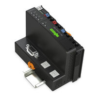
FC PROFIBUS G2 12MBd XTR Fieldbus Coupler PROFIBUS DP; 2. Generation; 12 MBd; Extreme For WAGO I/O SYSTEM 750 XTR
Brand:
WAGO
| Category:
Control Unit
| Size: 7 MB
Table of Contents
Table of Contents
3
1 Notes about this Documentation
8
Validity of this Documentation
8
Copyright
8
Symbols
9
Number Notation
11
Font Conventions
11
Table 1: Number Notation
11
Table 2: Font Conventions
11
2 Important Notes
12
Legal Bases
12
Personnel Qualifications
12
Subject to Changes
12
Use of the 750 Series in Compliance with Underlying Provisions
12
Disposal
13
Technical Condition of Specified Devices
13
2.1.4.1.1 Electrical and Electronic Equipment
13
2.1.4.1.2 Packaging
14
Safety Advice (Precautions)
15
3 System Description
18
Figure 1: Fieldbus Node (Example)
18
Manufacturing Number
20
Figure 2: Marking Area for Serial Numbers
20
Update
21
Figure 3: Update Matrix up to 2015
21
Figure 4: Update Matrix from 2016
21
Table 3: Legend for Figure "Update Matrix from 2016
21
Storage, Assembly and Transport
22
Assembly Guidelines/Standards
22
Power Supply
23
Isolation
23
Overcurrent Protection
23
Figure 5: Isolation for Fieldbus Couplers/Controllers (Example)
24
Connection
25
Figure 6: System Voltage for Fieldbus Couplers/Controllers (Example)
25
System Supply
25
Table 4: Legend for Figure "System Voltage for Fieldbus
25
Figure 7: System Supply for Fieldbus Coupler/Controller
26
Dimensioning
27
Table 5: Alignment
27
Connection
29
Field Supply
29
Figure 8: Field Supply for Fieldbus Couplers/Controllers (Example)
29
Table 6: Legend for Figure "Field Supply for Fieldbus
29
Figure 9: Supply Module with Fuse Carrier (Example 750-610/040-000)
31
Fusing Via Power Supply Module
31
Table 7: Power Supply Modules
31
Figure 10: Removing the Fuse Carrier
32
Figure 11: Opening the Fuse Carrier and Changing the Fuse
32
Figure 12: Changing the Fuse and Closing the Fuse Carrier
33
Figure 13: Push Back the Fuse Carrier
33
Figure 14: Fuse Modules for Automotive Fuses, Series 282
34
Figure 15: Fuse Modules for Automotive Fuses, Series 2006
34
Figure 16: Fuse Modules with Pivotable Fuse Carrier, Series 281
34
Fusing External
34
Figure 17: Fuse Modules with Pivotable Fuse Carrier, Series 2002
35
Power Supply for Mixed Operation
36
Table 8: XTR Supply Modules for Powering XTR Sections
36
Supplementary Power Supply Regulations
37
Table 9: Filter Modules for 24 V Power Supply
37
Figure 18: Power Supply Concept
38
Table 10: Legende for Figure "Power Supply Concept
38
Figure 19: Power Supply Example
39
Supply Example
39
Table 11: Legend for Figure "Power Supply Example
40
Power Supply Units
41
Grounding
42
Framework Assembly
42
Grounding the DIN Rail
42
Insulated Assembly
42
Table 12: WAGO Ground Wire Terminals
42
Figure 20: Carrier Rail Contact (Example)
43
Grounding Function
43
Shielding
44
Fieldbus Cables
44
Figure 21: Cable Shield at Ground Potential
44
General
44
Figure 22: Examples of the WAGO Shield Connecting System
45
Figure 23: Application of the WAGO Shield Connecting System
45
Shielded Signal Lines
45
WAGO Shield Connecting System
45
4 Device Description
46
View
47
Figure 24: View
47
Table 13: Legend for Figure "View
48
Connectors
49
Device Supply
49
Figure 25: Device Supply
49
Fieldbus Connection
50
Figure 26: Pin Assignment for D-Sub Fieldbus Connection (Female)
50
Table 14: Signal Assignment of the RS-485 Interface
50
Display Elements
51
Figure 27: Display Elements
51
Table 15: Display Elements Fieldbus Status
51
Table 16: Display Elements Node Status
51
Table 17: Display Elements Supply Voltage
51
Operating Elements
52
Service Interface
52
Figure 28: Service Interface (Closed and Opened Flap)
52
Table 18: Legend for Figure "Service Interface
52
Rotary Encoder Switch Station Address
53
Figure 29: Rotary Encoder Switch Station Address
53
Technical Data
54
Device Data
54
System Data
54
Table 19: Technical Data - Device
54
Table 20: Technical Data - System
54
Supply
55
Accessories
55
Table 21: Technical Data - Supply
55
Table 22: Technical Data - Accessories
55
Connection Type
56
Mechanical Conditions
56
Climatic Environmental Conditions
56
Table 23: Technical Data - Field Wiring
56
Table 24: Technical Data - Power Jumper Contacts
56
Table 25: Technical Data - Data Contacts
56
Table 26: Technical Data - Mechanical Conditions
56
Table 27: Technical Data - Climatic Environmental Conditions
56
Approvals
57
Standards and Guidelines
59
Table 28: Standards and Rated Conditions for Explosion Protection Applications
59
Table 29: Climatic and Mechanical Environmental Conditions and Shipbuilding
60
Table 30: EMC - Immunity to Interference
61
Table 31: EMC - Emission of Interference
63
Table 32: Standards and Rated Conditions for Rail Applications (en 50155)
64
5 Mounting
65
Installation Position
65
Figure 30: Mounting Positions
66
Overall Configuration
67
Mounting Onto Carrier Rail
68
Carrier Rail Properties
68
WAGO DIN Rails
69
Table 33: WAGO DIN Rails
69
Spacing
70
Figure 31: Spacing
70
Mounting Sequence
71
Inserting and Removing Devices
72
Inserting the Fieldbus Coupler/Controller
72
Figure 32: Release Tab of Extended ECO Fieldbus Coupler (Example)
72
Removing the Fieldbus Coupler/Controller
73
Inserting the I/O Module
73
Figure 33: Insert I/O Module (Example)
73
Figure 34: Snap the I/O Module into Place (Example)
74
Removing the I/O Module
75
Figure 35: Removing the I/O Module (Example)
75
6 Connect Devices
76
Data Contacts/Local Bus
76
Figure 36: Data Contacts
76
Power Contacts/Field Supply
77
Figure 37: Example for the Arrangement of Power Contacts
77
Connecting a Conductor to the CAGE CLAMP
78
Figure 38: Connecting a Conductor to a CAGE CLAMP
78
7 Function Description
79
Operating System
79
Figure 39: Operating System
79
Process Data Architecture
80
Basic Structure
80
Allocation of the Input and Output Data
80
Configuration of Process Data for PROFIBUS DP
81
Figure 40: Allocation of the Input and Output Data
81
8 Commissioning
82
Planning
82
GSD Files
83
Identifier Bytes
83
Table 34: Identifier Bytes - Configuration Identifier in the General Identifier Format
84
Table 35: Identifier Bytes - Configuration Identifier in the General Identifier Format (Header Byte)
84
Table 36: Identifier Bytes - Configuration Identifier in the Special Identifier Format (Length Byte)
85
Table 37: Identifier Bytes - Configuration Identifier in the Special Identifier Format (Datatype Byte)
86
Table 38: Table Modules
87
Table 39: Parameters - Settings
88
PI Configuration
89
Application Example
89
Table 40: Planned Station Configuration
89
Figure 41: Physical Station Design with Deactivated Parameter "Startup if Expected and Actual Configuration Differ" (Sample)
91
Physical Station Design with Deactivated Parameter "Startup if Expected and Actual Configuration Differ
91
Figure 42: Physical Station Design with Activated Parameter "Startup if Expected and Actual Configuration Differ" 1 (Sample)
92
Physical Station Design with Activated
92
Physical Station Design with Activated Parameter "Startup if Expected and Actual Configuration Differ" 1
92
Configuration Differ" 2
93
Figure 43: Physical Station Design with Activated Parameter "Startup if Expected and Actual Configuration Differ" 2 (Sample)
93
Parameterization
94
Standard Parameterization
94
Structured Parameterization
94
Parameterization on Demand
95
9 Diagnostics
96
LED Signaling
96
Figure 44: Display Elements
96
Table 41: LED Assignment for Diagnostics
96
Evaluating the Fieldbus Status
97
Table 42: Diagnosis of Fieldbus Status - Solution in Event of Error
97
Error Message Via Blink Code of the BUS LED
98
Table 43: Error Message Via Blink Code of the BUS LED
98
Evaluating Node Status - I/O LED (Blink Code Table)
99
Table 44: Node Status Diagnostics - Solution in Event of Error
99
Figure 45: Node Status - I/O LED Signaling
100
Figure 46: Error Message Coding
100
Table 45: Blink Code Table for the I/O LED Signaling, Error Code 1
101
Table 46: Blink Code Table for the I/O LED Signaling, Error Code 2
102
Table 47: Blink Code Table for the I/O LED Signaling, Error Code 3
103
Table 48: Blink Code Table for the I/O LED Signaling, Error Code 4
104
Table 49: Blink Code Table for the I/O LED Signaling, Error Code 5
104
Table 50: Blink Code Table for the 'I/O' LED Signaling, Error Code 6
105
Table 51: Blink Code Table for the 'I/O' LED Signaling, Error Code 7
105
Table 52: Blink Code Table for the I/O LED Signaling, Error Code 9
105
Table 53: Blink Code Table for I/O LED Signaling, Error Code 10
105
Table 54: Blink Code Table for I/O LED Signaling, Error Code 12
105
Evaluating Power Supply Status
106
Error Response
106
Fieldbus Failure
106
Table 55: Power Supply Status Diagnostics - Solution in Event of Error
106
Table 56: Diagnosis of Fieldbus Failure
106
Local Bus Failure
107
Device Diagnostics
107
Table 57: Diagnostics
108
Identifier-Related Diagnostics
109
Manufacturer ID
109
PROFIBUS DP Master Address
109
Station Status 1 to 3
109
Table 58: Identifier-Related Diagnostics - Structure
110
Table 59: Identifier-Related Diagnostics - Example
111
Device Status
112
Table 60: Device Status
112
Internal Status Messages and Arguments
113
Local Bus Messages and Arguments
113
PROFIBUS DP Status Messages and Arguments
113
Table 61: Internal Status Messages and Arguments
113
Table 62: Local Bus Messages and Arguments
113
Table 63: PROFIBUS-DP Status Messages and Arguments
113
Module Status
114
Table 64: Module Status
114
Channel-Specific Diagnostics
115
Table 65: Channel-Specific Diagnostics
115
Error Types of I/O Modules with Diagnostics Capability
116
Table 66: Error Types of I/O Modules with Diagnostics Capability
116
I/O Module Fault Cases
117
Table 67: I/O Module Fault Cases
117
Profisafe Parameterization Fault
119
Table 68: Status Messages
119
Table 69: Profisafe Parameterization Fault
119
Table 70: WAGO-Specific Error Messages
120
WAGO-Specific Error Messages
120
Acyclic Communication According to DP/V1
121
Table 71: MSAC1 Service
121
Table 72: MSAC2 Service
121
Data Areas
122
Complex I/O Modules, Slots 2
123
Fieldbus Coupler, Slots 0 and 1
123
Table 73: Fieldbus Coupler, Slots 0 and 1
123
Table 74: Complex 1-, 2-, 3- and 4-Channel I/O Modules, Slots 2
123
Digital I/O Modules, Slots 2
124
Table 75: Complex 8-Channel I/O Modules, Slots 2
124
Table 76: Digital I/O Modules, Slots 2
124
Figure 47: Coding Error Messages
126
Table 77: Meaning of the Octet 2 Error Messages
126
Table 78: Meaning of the Octet 3 Error Messages
127
Table 79: Meaning of the Octet 4 Error Messages
127
10 Fieldbus Communication
128
Cabling
129
Table 80: Technical Data, Bus Line
129
Table 81: Transfer Rate
129
Figure 48: Bus Connection
130
11 O Modules
132
Overview
132
12 Appendix
133
Configuration Identifiers
133
Fieldbus Coupler
133
Digital Input Modules
133
Table 82: Configuration Identifiers Fieldbus Coupler
133
Table 83: Configuration Identifiers Digital Input Modules
133
Digital Output Modules
135
Table 84: Configuration Identifiers Digital Output Modules
135
Power Supply Modules
136
Table 85: Configuration Identifiers Power Supply Modules
136
Analog Input Modules
137
Table 86: Configuration Identifiers Analog Input Modules
137
Analog Output Modules
138
Table 87: Configuration Identifiers Analog Output Modules
138
Special Modules
139
Table 88: Configuration Identifiers Special Modules
139
Configuration of the Process Data for PROFIBUS DP
141
Fieldbus Coupler (Process Data Channel)
141
Table 89: Fieldbus Coupler - Module Types
141
Table 90: Fieldbus Coupler - Number of Bytes
141
Digital Input Modules
142
Table 91: Digital Input Modules - Module Types
142
Table 92: Digital Input Modules - Number of Bits and Bytes
143
Table 93: Digital Input Modules - Process Image Information
144
Digital Output Modules
146
Table 94: Digital Output Modules - Module Types
146
Table 95: Digital Output Modules - Number of Bits and Bytes
147
Table 96: Digital Output Modules - Process Image Information
148
Digital Input/Output Modules
150
Table 97: Digital Input/Output Modules - Module Types
150
Table 98: Digital Input/Output Modules - Number of Bits and Bytes
150
Table 99: Digital Input/Output Modules - Process Image Information
150
Analog Input Modules
151
Table 100: Analog Input Modules - Module Types
151
Table 101: Analog Input Modules - Number of Bytes
152
Table 102: Analog Input Modules - Process Image Information
156
Analog Output Modules
164
Table 103: Analog Output Modules - Module Types
164
Table 104: Analog Output Modules - Number of Bytes
164
Table 105: Analog Output Modules - Process Image Information
165
Up/Down Counters
167
Table 106: Up/Down Counters - Module Types
167
Table 107: Up/Down Counters - Number of Bytes
167
Table 108: Up/Down Counters - Process Image Information
167
2-Channel Pulse Width Output Module
169
Modules for Path and Angle Measurement
169
Table 109: 2-Channel Pulse Width Output Module - Module Types
169
Table 110: 2-Channel Pulse Width Output Module - Number of Bytes
169
Table 111: 2-Channel Pulse Width Output Module - Process Image Information
169
Table 112: Modules for Path and Angle Measurement - Module Types
170
Table 113: Modules for Path and Angle Measurement - Number of Bytes
170
Table 114: Modules for Path and Angle Measurement
171
12.2.10 Serial Interfaces
173
Table 115: Serial Interfaces - Module Types
173
Table 116: Serial Interfaces - Number of Bytes
173
Table 117: Serial Interfaces - Process Image Information
174
12.2.11 DALI/DSI Master Module
178
Table 118: DALI/DSI Master Module - Module Types
178
Table 119: DALI/DSI Master Module - Number of Bytes
178
Table 120: DALI/DSI Master Module - Process Image Information
178
12.2.12 as Interface Master
179
Table 121: as Interface Master - Module Types
179
Table 122: as Interface Master - Number of Bytes
179
Table 123: as Interface Master - Process Image Information
180
12.2.13 Radio Receiver I/O Modules
182
Table 124: Radio Receiver I/O Modules - Module Types
182
Table 125: Radio Receiver I/O Modules - Number of Bytes
182
Table 126: Radio Receiver I/O Modules - Process Image Information
183
12.2.14 MP Bus Master Module
185
Table 127: MP Bus Master Module - Module Types
185
Table 128: MP Bus Master Module - Number of Bytes
185
Table 129: MP Bus Master Module - Process Image Information
186
2-Channel Vibration Velocity/Bearing Condition Monitoring VIB I/O
187
Table 130: 2-Channel Vibration Velocity/Bearing Condition Monitoring VIB I/O - Module Types
187
Table 131: Vibration Monitoring - Number of Bytes
187
Table 132: Vibration Monitoring - Process Image Information
188
12.2.16 Profisafe Modules
189
Table 133: Profisafe Modules - Module Types
189
Table 134: Profisafe Modules - Number of Bytes
189
Table 135: Profisafe Modules - Process Image Information
190
12.2.17 RTC Module
191
Table 136: RTC Module - Module Types
191
Table 137: RTC Module - Number of Bytes
191
Table 138: RTC Module - Process Image Information
191
12.2.18 Stepper Module
192
Table 139: Stepper Module - Module Types
192
Table 140: Stepper Module - Number of Bytes
192
Table 141: Stepper Module - Process Image Information
193
12.2.19 DC Drive Controller
194
Table 142: DC Drive Controller - Module Types
194
Table 143: DC Drive Controller - Number of Bytes
194
Table 144: DC Drive Controller - Process Image Information
194
12.2.20 IO-Link Master
195
Table 145: IO-Link Master - Module Types
195
Table 146: IO-Link Master - Number of Bytes
195
Table 147: IO-Link Master - Process Image Information
196
12.2.21 Supply Module with Diagnostics
198
Table 148: Supply Modules with Diagnostics - Module Types
198
Table 149: Supply Modules with Diagnostics - Number of Bytes
198
Table 150: Supply Modules with Diagnostics - Process Image Information
198
Parameter of the Fieldbus Coupler and the I/O Modules
199
Parameter of the Fieldbus Coupler
199
Parameters of the Station Proxy
199
Table 151: Parameters of the Fieldbus Coupler as Station Proxy (FC_SSV)
199
Parameters of the Process Data Channel
201
Table 152: Parameters of the Process Data Channel of the Fieldbus Coupler (FC_PZK)
201
Parameters of the I/O Modules
202
Parameters of the Digital Input Modules
202
Parameters of the Digital Output Modules
202
Table 153: Parameters of the 1, 2, 4, 8 and 16-Channel Digital Input Modules (DI)
202
Table 154: Parameters of the 2-Channel Digital Input Modules (DI_DIA)
202
Table 155: Parameters of the 2, 4, 8 and 16-Channel Digital Output Modules (DO)
203
Table 156: Parameters of the 1, 2, 4 and 8-Channel Digital Output Modules (DO_DIA)
203
Parameters of the Digital Input/Output Modules
204
Table 157: Parameters of the 8-Channel Digital Input/Output Modules (DO_DI)
204
Parameters of the Analog Input Modules
205
Table 158: Parameters of the 1, 2, 3 and 4-Channel Analog Input Modules (AI)
205
Table 159: Parameters of the 4(2)-Channel Analog Input Modules (AI_PAR)
206
Table 160: Parameters of the 2-Channel Analog Input Modules HART (AI_HART)
207
Table 161: Parameters of the 4 (8)-Channel Analog Input Modules (AI_PAR)
208
Table 162: Parameter of the 3-Phase Power Measurement Modules (1AI_PAR)
209
Parameters of the Analog Output Modules
211
Table 163: Parameters of the 2 and 4-Channel Analog Output Modules (AO)
211
Table 164: Parameters of the 2-Channel Analog Output Modules (AO_PAR)
211
Parameters of the Up/Down Counters
213
Parameters of the 2-Channel Pulse Width Output Module
213
Table 165: Parameter of the Up/Down Counters (CNT)
213
Table 166: Parameters of the 2-Channel Pulse Width Output Module (PWM)
213
Parameters of the Modules for the Distance and Angle Measurement
214
Table 167: Parameters of the Modules for the Distance and Angle Measurement (SSI, ENC, DII)
214
Parameters of the Serial Interface
215
Table 168: Parameters of the Serial Interface (SER)
215
Table 169: Parameters of the Serial Interface (SER_PAR)
216
12.3.2.10 Parameters of the DALI/DSI Master Modules
217
12.3.2.11 Parameters of the as Interface Master
217
12.3.2.12 Parameters of the Enocean Radio Receiver
217
Table 170: Parameters of the DALI/DSI Master Modules (DALI)
217
Table 171: Parameters of the as Interface Master (ASI)
217
Parameters of the Bluetooth ® RF Transceiver
218
Table 172: Parameters of the Enocean Radio Receiver (ENOC)
218
Table 173: Parameters of the Bluetooth
218
12.3.2.14 Parameters of the MP-Bus Master Module
219
Parameters of the 2-Channel Vibration Velocity / Roller Bearing Condition Monitoring VIB I/O
219
Table 174: Parameters of the MP-Bus Master Module (MP_BUS)
219
Table 175: Parameters of the VIB I/O 2-Channel Vibration Velocity/Bearing Condition Monitoring (VIB_IO)
219
12.3.2.16 Parameters of the Profisafe I/O Modules
220
Table 176: Parameters of the Profisafe V1 I/O Modules (PSAFE_V1)
220
Table 177: Parameters of the Profisafe V2 I/O
222
Table 178: Parameters of the Profisafe V2 I/O Modules with Ipar Server Functionality (Psafe_V2_Ipar)
222
12.3.2.17 Parameters of the RTC Module
223
12.3.2.18 Parameters of the Stepper Modules
223
Table 179: Parameters of the RTC Module (RTC)
223
Table 180: Parameter of the Stepper Modules (STEPPER)
223
12.3.2.19 Parameters of the DC Drive Controller
224
12.3.2.20 Parameters of the IO-Link Master
224
Parameter Set 0
224
Table 181: Parameters of the DC Drive Controller (DC_DRIVE)
224
Table 182: Parameter Set 0 of the IO-Link Master (IOL_M)
224
Parameter Set 2
225
Table 183: Parameter Set 2 of the IO-Link-Masters (IOL_M)
225
12.3.2.21.2 Parameters of the Power Supply Modules
226
Table 184: Parameters of the Power Supply Modules with Diagnostics (DIA)
226
Acyclic Communication According to DP/V1
227
Data Blocks of the Digital Input/Output Modules
227
Table 185: Data Blocks of the Digital Input/Output Modules
227
Digital Input Modules and Supply Modules
229
Table 186: Digital Input Modules and Supply Modules
229
Digital Output and Digital Input/Output Modules
230
Table 187: Digital Output and Digital Input/Output Modules
230
Data Blocks for Complex I/O Modules with up to 4 Signal Channels
232
Table 188: Data Blocks for Complex I/O Modules with up to 4 Signal Channels
232
Analog Input/Output Modules
234
Table 189: Analog Input/Output Modules
234
Up/Down Counter, Pulse Width Output Module and Path and Angle Measurement
235
Table 190: Up/Down Counter, Pulse Width Output Modules and Path and Angle Measurement
235
Serial Interfaces, Data Exchange Modules and Radio Receiver I/O Modules
236
Table 191: Serial Interfaces, Data Exchange Modules and Radio Receiver I/O Modules
236
DALI/DSI Master Modules, as Interface Master, MP Bus Master Modules and IO-Link Master
237
Table 192: DALI/DSI Master Modules, as Interface Master, MP Bus Master Modules and IO-Link Master
237
2-Channel Vibration Velocity/Bearing Condition Monitoring VIB I/O, RTC Modules, Stepper Modules, DC Drive Controller and I/O Modules Profisafe
238
Table 193: 2-Channel Vibration Velocity/Bearing Condition Monitoring VIB I/O, RTC Modules, Stepper Modules, DC Drive Controller and I/O Modules Profisafe
238
Data Blocks of the Complex I/O Modules with 8 Signal Channels
239
Table 194: Data Blocks of the Complex I/O Modules with 8 Signal Channels
239
Analog Input Modules
242
Table 195: Analog Input Modules
242
Data Blocks for Identification and Maintenance Purposes (I&M)
243
Fieldbus Coupler, Slots 0 and 1
244
Table 196: I&M0 of the Fieldbus Coupler 750-333
244
Table 197: I&M1 of the Fieldbus Coupler 750-333
245
Table 198: I&M2 of the Fieldbus Coupler 750-333
245
Table 199: I&M3 of the Fieldbus Coupler 750-333
245
IO-Link Master (75X-657), Slot 2 to 64
246
Table 200: I&M4 of the Fieldbus Coupler 750-333
246
Table 201: I&M0 of the IO-Link Master 75X-657
246
Table 202: I&M1 of the IO-Link Master 75X-657
247
Table 203: I&M2 of the IO-Link Master 75X-657
247
Table 204: I&M3 of the IO-Link Master 75X-657
247
Table 205: I&M4 of the IO-Link Master 75X-657
248
13 Use in Hazardous Environments
249
Marking Configuration Examples
250
Marking for Europe According to ATEX and Iecex
250
Figure 49: Marking Example According to ATEX and Iecex
250
Figure 50: Text Detail - Marking Example According to ATEX and Iecex
250
Table 206: Description of Marking Example According to ATEX and Iecex
251
Figure 51: Marking Example for Approved Ex I I/O Module According to ATEX and Iecex
252
Figure 52: Text Detail - Marking Example for Approved Ex I I/O Module According to ATEX and Iecex
252
Table 207: Description of Marking Example for Approved Ex I I/O Module According to ATEX and Iecex
253
Marking for the United States of America (NEC) and Canada (CEC)
254
Figure 53: Marking Example According to NEC
254
Figure 54: Text Detail - Marking Example According to NEC 500
254
Table 208: Description of Marking Example According to NEC 500
254
Figure 55: Text Detail - Marking Example for Approved
255
Figure 56: Text Detail - Marking Example for Approved
255
Table 209: Description of Marking Example for Approved
255
Table 210: Description of Marking Example for Approved
255
Figure 57: Text Detail - Marking Example for Approved
256
Table 211: Description of Marking Example for Approved
256
Installation Regulations
257
Special Notes Including Explosion Protection
257
Special Notes Regarding ANSI/ISA Ex
259
List of Figures
260
List of Tables
262
Advertisement
Advertisement
Related Products
WAGO 750-363/0040-0000
WAGO IO-Link Master 750-657
WAGO 750-494/000-001
WAGO 750-654
WAGO 750-637/000-001
WAGO 750-1606/040-000
WAGO 750-624/040-00 Series
WAGO 750-486/040-000
WAGO 750-523
WAGO 750-404/040-003
WAGO Categories
I/O Systems
Control Unit
Power Supply
Switch
Controller
More WAGO Manuals
Login
Sign In
OR
Sign in with Facebook
Sign in with Google
Upload manual
Upload from disk
Upload from URL