
Related Manuals for WAGO 750-325


Summary of Contents for WAGO 750-325
- Page 1 Manual WAGO-I/O-SYSTEM 750 750-325 CC-Link Fieldbus Coupler 156 kBaud ... 10 MBaud; digital and analog signals Version 2.0.1...
- Page 2 We wish to point out that the software and hardware terms as well as the trademarks of companies used and/or mentioned in the present manual are generally protected by trademark or patent. WAGO is a registered trademark of WAGO Verwaltungsgesellschaft mbH. Manual Version 2.0.1...
- Page 3 Shielding ....................41 3.7.1 General .................... 41 3.7.2 Fieldbus Cables ................41 3.7.3 Shielded Signal Lines............... 42 3.7.4 WAGO Shield Connecting System ........... 42 Device Description .................. 43 View ..................... 44 Connectors ................... 46 4.2.1 Device Supply .................. 46 Manual Version 2.0.1...
- Page 4 Table of Contents WAGO-I/O-SYSTEM 750 750-325 CC-Link Fieldbus Coupler 4.2.2 Fieldbus Connection ................ 47 4.2.2.1 Connection Using Multi Connectors ..........47 Display Elements .................. 48 Operating Elements ................49 4.4.1 Service Interface ................49 4.4.2 Rotary Encoder Switch Station Address ........... 50 4.4.3...
- Page 5 WAGO-I/O-SYSTEM 750 Table of Contents 750-325 CC-Link Fieldbus Coupler 7.3.2 Assigning the I/O Module Data to the CC-Link Address Range ..82 7.3.2.1 Example Type 1 – Digital Input ............ 82 7.3.2.2 Example Type 6 – 2-channel digital input; Acknowledgement;...
- Page 6 Type 64 - 8-channel analog output ..........160 10.2.64 Type 65 - 4-channel analog input; Diagnostics ....... 161 Service ....................162 11.1 Replacing 750-310 by 750-325 ............162 11.2 Disposal ..................... 162 11.2.1 Electrical and Electronic Equipment ..........163 11.2.2 Packaging ..................
- Page 7 WAGO-I/O-SYSTEM 750 Table of Contents 750-325 CC-Link Fieldbus Coupler Use in Hazardous Environments ............165 12.1 Marking Configuration Examples ............166 12.1.1 Marking for Europe According to ATEX and IECEx ......166 12.1.2 Marking for the United States of America (NEC) and Canada (CEC) .....................
- Page 8 Validity of this Documentation This documentation is only applicable to the “CC-Link Fieldbus Coupler” (750- 325). The product “CC-Link Fieldbus Coupler” (750-325) shall only be installed and operated according to the instructions in this manual and the system description for the WAGO-I/O-SYSTEM 750.
- Page 9 WAGO-I/O-SYSTEM 750 Notes about this Documentation 750-325 CC-Link Fieldbus Coupler Symbols Personal Injury! Indicates a high-risk, imminently hazardous situation which, if not avoided, will result in death or serious injury. Personal Injury Caused by Electric Current! Indicates a high-risk, imminently hazardous situation which, if not avoided, will result in death or serious injury.
- Page 10 Notes about this Documentation WAGO-I/O-SYSTEM 750 750-325 CC-Link Fieldbus Coupler Additional Information: Refers to additional information which is not an integral part of this documentation (e.g., the Internet). Manual Version 2.0.1...
-
Page 11: Table 1: Number Notation
WAGO-I/O-SYSTEM 750 Notes about this Documentation 750-325 CC-Link Fieldbus Coupler Number Notation Table 1: Number Notation Number Code Example Note Decimal Normal notation Hexadecimal 0x64 C notation Binary '100' In quotation marks, nibble separated '0110.0100' with dots (.) Font Conventions... - Page 12 2.1.1 Subject to Changes WAGO Kontakttechnik GmbH & Co. KG reserves the right to provide for any alterations or modifications. WAGO Kontakttechnik GmbH & Co. KG owns all rights arising from the granting of patents or from the legal protection of utility patents.
- Page 13 These modules contain no parts that can be serviced or repaired by the user. The following actions will result in the exclusion of liability on the part of WAGO Kontakttechnik GmbH & Co. KG: •...
- Page 14 Important Notes WAGO-I/O-SYSTEM 750 750-325 CC-Link Fieldbus Coupler Safety Advice (Precautions) For installing and operating purposes of the relevant device to your system the following safety precautions shall be observed: Do not work on devices while energized! All power sources to the device shall be switched off prior to performing any installation, repair or maintenance work.
- Page 15 WAGO-I/O-SYSTEM 750 Important Notes 750-325 CC-Link Fieldbus Coupler Use SELV power source only! The fieldbus coupler/controller must only be powered from a SELV (Safety Extra Low Voltage) power source. Do not use in telecommunication circuits! Only use devices equipped with ETHERNET or RJ-45 connectors in LANs.
- Page 16 Important Notes WAGO-I/O-SYSTEM 750 750-325 CC-Link Fieldbus Coupler Do not reverse the polarity of connection lines! Avoid reverse polarity of data and power supply lines, as this may damage the devices involved. Avoid electrostatic discharge! The devices are equipped with electronic components that may be destroyed by electrostatic discharge when touched.
-
Page 17: Figure 1: Fieldbus Node (Example)
The communication between the fieldbus coupler/controller and the I/O modules is carried out via a local bus. The components of the WAGO I/O SYSTEM 750 have clear termination points, light emitting diodes for status display, plug-in mini WSB tags and group marker cards for labeling. -
Page 18: Figure 2: Marking Area For Serial Numbers
System Description WAGO-I/O-SYSTEM 750 750-325 CC-Link Fieldbus Coupler The serial number indicates the delivery status directly after production. This number is part of the labeling on the side of each component. Figure 2: Marking Area for Serial Numbers There are two serial numbers in two rows in the side marking. They are left of the release tab. -
Page 19: Figure 3: Update Matrix Up To 2015
WAGO-I/O-SYSTEM 750 System Description 750-325 CC-Link Fieldbus Coupler Figure 3: Update Matrix up to 2015 From 2016, the matrix has rows to enter the “FA” production or work order number and to enter the “PD” production date and “AZ” item number. - Page 20 System Description WAGO-I/O-SYSTEM 750 750-325 CC-Link Fieldbus Coupler Storage, Assembly and Transport Whenever possible, the components are to be stored in their original packaging. Likewise, the original packaging provides optimal protection during transport. When assembling or repacking the components, the contacts must not be soiled or damaged.
- Page 21 Therefore, you should always dimension the overcurrent protection according to the anticipated power usage. The system and field voltage of the WAGO-I/O-SYSTEMs 750 is supplied on the head stations and bus supply modules. For components that work with extra low voltage, only SELV/PELV voltage sources should be used.
-
Page 22: Figure 5: Isolation For Fieldbus Couplers/Controllers (Example)
System Description WAGO-I/O-SYSTEM 750 750-325 CC-Link Fieldbus Coupler • Electronics of the fieldbus couplers/controllers and the I/O modules (local bus) • All I/O modules have an electrical isolation between the electronics (local bus, logic) and the field electronics. Some digital and analog input modules have each channel electrically isolated, please see catalog. -
Page 23: Figure 6: System Supply Via Fieldbus Coupler/Controller (Left) And Via Internal
System Supply 3.5.3.1 Connection The WAGO-I/O-SYSTEM 750 requires a 24 V direct current system supply. The power supply is provided via the fieldbus coupler/controller and, if necessary, in addition via internal system supply modules 750-613. The power supply is reverse voltage protected. -
Page 24: Figure 7: System Voltage For Standard Couplers/Controllers And Extended
System Description WAGO-I/O-SYSTEM 750 750-325 CC-Link Fieldbus Coupler System supply only with appropriate fuse protection! Without overcurrent protection, the electronics can be damaged. If you implement the overcurrent protection for the system supply with a fuse, a fuse, max. 2 A, slow-acting, should be used. -
Page 25: Table 5: Alignment
WAGO-I/O-SYSTEM 750 System Description 750-325 CC-Link Fieldbus Coupler Table 5: Alignment Internal current consumption Current consumption via system voltage (5 V for electronics of I/O modules and fieldbus coupler/controller). Total current for I/O modules Available current for the I/O modules. - Page 26 (750-613), e. g. in the middle of the node, should be added. Recommendation Utilize the smartDESIGNER feature WAGO ProServe ® software to configure fieldbus node assembly. You can test the configuration via the integrated plausibility check.
- Page 27 WAGO-I/O-SYSTEM 750 System Description 750-325 CC-Link Fieldbus Coupler Fieldbus coupler or controller = Sum of all the internal current consumption of the (5 V) total connected I/O modules + internal current consumption of the fieldbus coupler/controller Internal system supply module...
-
Page 28: Figure 8: Field Supply For Standard Couplers/Controllers And Extended Eco
System Description WAGO-I/O-SYSTEM 750 750-325 CC-Link Fieldbus Coupler 3.5.4 Field Supply 3.5.4.1 Connection Sensors and actuators can be directly connected to the relevant channel of the I/O module in 1, 2, 3 or 4 conductor connection technology. The I/O module supplies power to the sensors and actuators. - Page 29 WAGO-I/O-SYSTEM 750 System Description 750-325 CC-Link Fieldbus Coupler The field-side power supply is automatically derived from the power jumper contacts when snapping an I/O module. The current load of the power contacts must not exceed 10 A on a continual basis.
-
Page 30: Figure 9: Supply Module With Fuse Carrier (Example 750-610)
System Description WAGO-I/O-SYSTEM 750 750-325 CC-Link Fieldbus Coupler 3.5.4.2 Fusing via Power Supply Module Internal fusing of the field supply is possible for various field voltages via an appropriate power supply module. Table 7: Power Supply Modules Order No. Field Voltage... -
Page 31: Figure 10: Removing The Fuse Carrier
WAGO-I/O-SYSTEM 750 System Description 750-325 CC-Link Fieldbus Coupler In order to insert or change a fuse, or to switch off the voltage in succeeding I/O modules, the fuse holder may be pulled out. In order to do this, use a screwdriver for example, to reach into one of the slits (one on both sides) and pull out the holder. -
Page 32: Figure 12: Changing The Fuse And Closing The Fuse Carrier
System Description WAGO-I/O-SYSTEM 750 750-325 CC-Link Fieldbus Coupler Figure 12: Changing the Fuse and Closing the Fuse Carrier After changing the fuse, the fuse carrier is pushed back into its original position. Figure 13: Push Back the Fuse Carrier Manual... -
Page 33: Figure 14: Fuse Modules For Automotive Fuses, Series 282
If you alternatively implement the overcurrent protection for the field supply with an external fuse, an F 10 A fuse should be used. For the external fusing, the fuse modules of the WAGO series 282, 2006, 281 and 2002 are suitable for this purpose. -
Page 34: Figure 17: Fuse Modules With Pivotable Fuse Carrier, Series 2002
System Description WAGO-I/O-SYSTEM 750 750-325 CC-Link Fieldbus Coupler Figure 17: Fuse Modules with Pivotable Fuse Carrier, Series 2002 Manual Version 2.0.1... -
Page 35: Figure 18: Power Supply Concept
750-325 CC-Link Fieldbus Coupler 3.5.5 Supplementary Power Supply Regulations The WAGO-I/O-SYSTEM 750 can also be used in shipbuilding or offshore and onshore areas of work (e. g. working platforms, loading plants). This is demonstrated by complying with the standards of influential classification companies such as Germanischer Lloyd and Lloyds Register. -
Page 36: Figure 19: Supply Example For Standard Couplers/Controllers
System Description WAGO-I/O-SYSTEM 750 750-325 CC-Link Fieldbus Coupler 3.5.6 Supply Example Suppl Sggggggggggggggggg The system supply and the field supply shall be separated! You should separate the system supply and the field supply in order to ensure bus operation in the event of a short-circuit on the actuator side. -
Page 37: Table 9: Legend For Figure "Supply Example For Fieldbus Coupler/Controller
WAGO-I/O-SYSTEM 750 System Description 750-325 CC-Link Fieldbus Coupler Table 9: Legend for Figure “Supply Example for Fieldbus Coupler/Controller” Pos. Description Power Supply on fieldbus coupler/controller via external Supply Module Power Supply with optional ground Internal System Supply Module Separation Module recommended... - Page 38 750-325 CC-Link Fieldbus Coupler 3.5.7 Power Supply Unit The WAGO-I/O-SYSTEM 750 requires a 24 VDC voltage (system supply). Recommendation A stable power supply cannot always be assumed everywhere. Therefore, you should use regulated power supplies to ensure the quality of the supply voltage.
-
Page 39: Table 10: Wago Ground Wire Terminals
The optimal setup is a metallic assembly plate with grounding connection which is electrically conductive linked to the carrier rail. The separate grounding of the carrier rail can be easily set up with the aid of the WAGO ground wire terminals. Table 10: WAGO Ground Wire Terminals Order No. Description 283-609 1-conductor ground (earth) terminal block make an automatic contact to the carrier rail;... -
Page 40: Figure 20: Carrier Rail Contact (Example)
System Description WAGO-I/O-SYSTEM 750 750-325 CC-Link Fieldbus Coupler 3.6.2 Grounding Function The grounding function increases the resistance against electro-magnetic interferences. Some components in the I/O system have a carrier rail contact that dissipates electro-magnetic interferences to the carrier rail. Figure 20: Carrier Rail Contact (Example) -
Page 41: Figure 21: Cable Shield At Ground Potential
Higher shielding performance is achieved via low-impedance connection between shield and ground. For this purpose, connect the shield over a large surface area, e.g., WAGO shield connecting system. This is especially recommended for large-scale systems where equalizing current or high impulse- type currents caused by atmospheric discharge may occur. -
Page 42: Figure 22: Examples Of The Wago Shield Connecting System
I/O module can be achieved even in the presence of interference acting on the signal cable. On some WAGO devices you can directly clamp the shield. For all other devices use the WAGO shield connecting system. - Page 43 Device Description 750-325 CC-Link Fieldbus Coupler Device Description The 750-325 CC-Link Fieldbus Coupler connects the WAGO-I/O-SYSTEM with the CC-Link protocol. In the head station, all input signals from the sensors are combined. After connecting the head station, the head station determines which I/O modules are on the node and creates a local process image from theirs data.
-
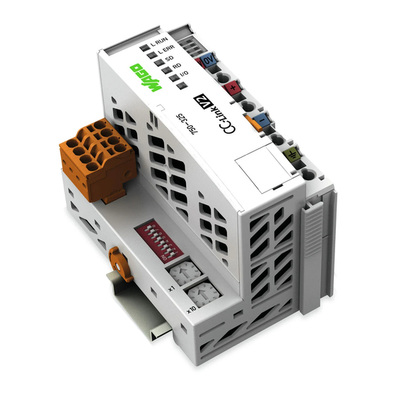
Page 44: Figure 24: View Fieldbus Coupler Cc-Link V 2.0
Device Description WAGO-I/O-SYSTEM 750 750-325 CC-Link Fieldbus Coupler View The view shows three parts: • The fieldbus connection, the DIP switch and the rotary encoder switches are located on the left side. • LEDs for operating status, bus communication, error messages and diagnostics, as well as the service interface are in the middle area. -
Page 45: Table 11: Legend For Figure "View Fieldbus Coupler Cc-Link V2.0
WAGO-I/O-SYSTEM 750 Device Description 750-325 CC-Link Fieldbus Coupler Table 11: Legend for Figure “View Fieldbus Coupler CC-Link V2.0” Desig- Pos. Meaning Details see Section nation L RUN, L ERR, „Device Description“ > Status LEDs Fieldbus SD, RD, „Display Elements“ Carrier for additional marking possibility on two miniature WSB markers “Device Description”... -
Page 46: Figure 25: Device Supply
Device Description WAGO-I/O-SYSTEM 750 750-325 CC-Link Fieldbus Coupler Connectors 4.2.1 Device Supply The device is powered via terminal blocks with CAGE CLAMP ® connections. The device supply generates the necessary voltage to power the electronics of the device and the internal electronics of the connected I/O modules. -
Page 47: Figure 26: Fieldbus Connections, Series 231 (Mcs)
WAGO-I/O-SYSTEM 750 Device Description 750-325 CC-Link Fieldbus Coupler 4.2.2 Fieldbus Connection The socket is arranged physically lower, allowing the coupler to fit in an 80 mm high enclosure after plug connection with the spring bar. 4.2.2.1 Connection Using Multi Connectors The CC-Link fieldbus connection is made on the 4-pole pin strip via a 2-wire spring bar 231 Series MCS. -
Page 48: Figure 27: Display Elements
Device Description WAGO-I/O-SYSTEM 750 750-325 CC-Link Fieldbus Coupler Display Elements The operating condition of the fieldbus coupler or the node is displayed with the help of illuminated indicators in the form of light-emitting diodes (LEDs). The LED information is routed to the top of the case by light guides. In some cases, the LEDs are multi-colored (red, green or orange). -
Page 49: Figure 28: Service Interface (Closed And Opened Flap)
4.4.1 Service Interface The service interface is located behind the flap. It is used for the communication with the WAGO-I/O-CHECK and for downloading the firmware updates. Figure 28: Service Interface (Closed and Opened Flap) Table 16: Legend for Figure “Service Interface (Closed and Opened Flap)”... -
Page 50: Figure 29: Rotary Encoder Switch Station Address
Device Description WAGO-I/O-SYSTEM 750 750-325 CC-Link Fieldbus Coupler 4.4.2 Rotary Encoder Switch Station Address Two decimal rotary encoder switches on the fieldbus coupler are used to set the station address. Figure 29: Rotary Encoder Switch Station Address The “x1” switch determines the unit position of the address. -
Page 51: Figure 30: Dip Switch
WAGO-I/O-SYSTEM 750 Device Description 750-325 CC-Link Fieldbus Coupler 4.4.3 DIP Switch The DIP switch on the fieldbus coupler is used to parameterize the fieldbus coupler. Figure 30: DIP Switch The 8-pole DIP switch is used to set • the operation mode •... -
Page 52: Table 18: Extended Cyclic Setting
Device Description WAGO-I/O-SYSTEM 750 750-325 CC-Link Fieldbus Coupler 4.4.3.2 Extended Cyclic Setting The extended cyclic setting is set via pins 6 and 7 of the DIP switch. This setting is only possible with CC-Link V 2.0. Table 18: Extended Cyclic Setting... -
Page 53: Table 21: Technical Data - Device Data
WAGO-I/O-SYSTEM 750 Device Description 750-325 CC-Link Fieldbus Coupler Technical Data 4.5.1 Device Data Table 21: Technical Data – Device Data Width 61.5 mm Height (from upper-edge of DIN 35) 71.9 mm Length 100 mm Weight approx. 149 g 4.5.2 System Data Table 22: Technical Data –... -
Page 54: Table 23: Technical Data - Supply
Device Description WAGO-I/O-SYSTEM 750 750-325 CC-Link Fieldbus Coupler Output process image For 1, 2, 3, 4 station addresses: RY (digital outputs): V1.1: 16, 48, 80, 112 bits V2.0: 16, 48, 80, 112 bits (1 cycle) 16, 80, 144, 208 bits (2 cycles) -
Page 55: Table 26: Technical Data - Power Jumper Contacts
WAGO-I/O-SYSTEM 750 Device Description 750-325 CC-Link Fieldbus Coupler Table 26: Technical Data – Power Jumper Contacts Power jumper contacts Spring contact, self-cleaning Table 27: Technical Data – Data Contacts Data contacts Slide contact, hard gold plated, self- cleaning 4.5.6 Climatic Environmental Conditions Table 28: Technical Data –... -
Page 56: Table 29: Technical Data - Mechanical Strength
Device Description WAGO-I/O-SYSTEM 750 750-325 CC-Link Fieldbus Coupler 4.5.7 Mechanical Strength Table 29: Technical Data – Mechanical Strength Vibration resistance Acc. to IEC 60068-2-6 Comment to the vibration resistance: a) Type of oscillation: sweep with a rate of change of 1 octave per minute 10 Hz ≤... - Page 57 Approvals More information about approvals. Detailed references to the approvals are listed in the document “Overview Approvals WAGO I/O SYSTEM 750”, which you can find via the internet under: www.wago.com DOWNLOADS Documentation System Description. The following approvals have been granted to 750-325 fieldbus coupler:...
- Page 58 Device Description WAGO-I/O-SYSTEM 750 750-325 CC-Link Fieldbus Coupler Standards and Guidelines 750-325 fieldbus coupler meets the following standards and guidelines: UL Ordinary Locations UL Standard for Safety – UL 61010-2-201 for Industrial Control Equipment UL Hazardous Locations STANDARD FOR SAFETY –...
- Page 59 WAGO-I/O-SYSTEM 750 Mounting 750-325 CC-Link Fieldbus Coupler Mounting Installation Position Along with horizontal and vertical installation, all other installation positions are allowed. Use an end stop in the case of vertical mounting! In the case of vertical assembly, an end stop has to be mounted as an additional safeguard against slipping.
- Page 60 Mounting WAGO-I/O-SYSTEM 750 750-325 CC-Link Fieldbus Coupler Increase the total length using a coupler module for internal data bus extension! You can increase the total length of a fieldbus node by using a 750-628 I/O Module (coupler module for internal data bus extension). For such a configuration, attach a 750-627 I/O Module (end module for internal data bus extension) after the last I/O module of a module assembly.
- Page 61 WAGO Kontakttechnik GmbH & Co. KG supplies standardized carrier rails that are optimal for use with the I/O system. If other carrier rails are used, then a technical inspection and approval of the rail by WAGO Kontakttechnik GmbH & Co. KG should take place.
-
Page 62: Figure 31: Spacing
Mounting WAGO-I/O-SYSTEM 750 750-325 CC-Link Fieldbus Coupler 5.3.2 WAGO DIN Rails WAGO carrier rails meet the electrical and mechanical requirements shown in the table below. Table 30: WAGO DIN Rails Item No. Description 210-112 35 × 7.5; 1 mm; steel; bluish, tinned, chromed; slotted 210-113 35 ×... - Page 63 Always plug a bus end module (750-600) onto the end of the fieldbus node! You must always use a bus end module at all fieldbus nodes with WAGO I/O SYSTEM 750 fieldbus couplers or controllers to guarantee proper data transfer.
- Page 64 Mounting WAGO-I/O-SYSTEM 750 750-325 CC-Link Fieldbus Coupler Inserting and Removing Devices Do not work when devices are energized! High voltage can cause electric shock or burns. Switch off all power to the device prior to performing any installation, repair or maintenance work.
-
Page 65: Figure 32: Release Tab Of Extended Eco Fieldbus Coupler (Example)
WAGO-I/O-SYSTEM 750 Mounting 750-325 CC-Link Fieldbus Coupler 5.6.1 Inserting the Fieldbus Coupler/Controller When replacing the fieldbus coupler/controller for an already available fieldbus coupler/controller, position the new fieldbus coupler/controller so that the tongue and groove joints to the subsequent I/O module are engaged. -
Page 66: Figure 33: Inserting I/O Module (Example)
Mounting WAGO-I/O-SYSTEM 750 750-325 CC-Link Fieldbus Coupler 5.6.3 Inserting the I/O Module Position the I/O module in such a way that the groove and spring are connected to the preceding and following components. Figure 33: Inserting I/O Module (Example) Press the I/O module into the assembly until the I/O module snaps into the carrier rail. -
Page 67: Figure 35: Removing The I/O Module (Example)
WAGO-I/O-SYSTEM 750 Mounting 750-325 CC-Link Fieldbus Coupler 5.6.4 Removing the I/O Module Remove the I/O module from the assembly by pulling the release tab. Figure 35: Removing the I/O Module (Example) Electrical connections for data or power jumper contacts are disconnected when removing the I/O module. -
Page 68: Figure 36: Data Contacts
Connect Devices WAGO-I/O-SYSTEM 750 750-325 CC-Link Fieldbus Coupler Connect Devices Data Contacts/Local Bus Communication between the fieldbus coupler/controller and the I/O modules as well as the system supply of the I/O modules is carried out via the local bus. The contacting for the local bus consists of 6 data contacts, which are available as self-cleaning gold spring contacts. -
Page 69: Figure 37: Example For The Arrangement Of Power Contacts
WAGO-I/O-SYSTEM 750 Connect Devices 750-325 CC-Link Fieldbus Coupler Power Contacts/Field Supply Risk of injury due to sharp-edged blade contacts! The blade contacts are sharp-edged. Handle the I/O module carefully to prevent injury. Do not touch the blade contacts. Self-cleaning power jumper contacts used to supply the field side are located on the right side of most of the fieldbus couplers/controllers and on some of the I/O modules. -
Page 70: Figure 38: Connecting A Conductor To A Cage Clamp
Do not connect more than one conductor at one single connection! If more than one conductor must be routed to one connection, these must be connected in an up-circuit wiring assembly, for example using WAGO feed- through terminals. For opening the CAGE CLAMP ®... -
Page 71: Figure 39: Initialization
WAGO-I/O-SYSTEM 750 Function Description 750-325 CC-Link Fieldbus Coupler Function Description Initialization After master configuration and electrical installation of the fieldbus station, the system is operative. The coupler begins running up after switching on the power supply. Upon initialization, the fieldbus coupler determines the I/O modules and configuration. - Page 72 Additional Information For the fieldbus-specific structure of the process values of any I/O module within the 750 or 753 Series of the WAGO-I/O-SYSTEM, refer to Section “I/O modules” >> “Structure of process data for CC-Link“. The coupler creates an internal local process image on the basis of the data width, the type of I/O module and the position of the module in the node.
-
Page 73: Table 31: Assigned Areas Depending In The Cc-Link Configuration Setting
WAGO-I/O-SYSTEM 750 Function Description 750-325 CC-Link Fieldbus Coupler The areas shown in the following table are allocated for the digital data (remote I/O) depending on the number of occupied stations and depending on the selected cycles of the extended cyclic setting assigned from the master station. - Page 74 Function Description WAGO-I/O-SYSTEM 750 750-325 CC-Link Fieldbus Coupler 7.2.2.2 Remote I/O Area The remote I/O area for digital data is divided into the user-defined area and system area as shown below. The following example table shows the data area of the remote I/Os for CC-Link V1.1 and identical for CC-Link V2.0 at the setting of one cycle.
-
Page 75: Table 32: Data Area Of The Remote I/Os (Example V1.1 And V2.0 At The Setting Of One Cycle)
WAGO-I/O-SYSTEM 750 Function Description 750-325 CC-Link Fieldbus Coupler Table 32: Data Area of the Remote I/Os (Example V1.1 and V2.0 at the Setting of one Cycle) Link Input Link Output User defined Area User defined Area RXm0 RYm0 RXm1 Depends on number of... -
Page 76: Table 33: System Area Flags
Function Description WAGO-I/O-SYSTEM 750 750-325 CC-Link Fieldbus Coupler The following table describes the system area flags. Table 33: System Area Flags System Area-Flags Description Used when the fieldbus coupler requests the RX(m+n)8 Initial data processing request flag initial processing to the master after the power... -
Page 77: Table 35: Position Of Remote I/O System Area V2.0 At The Setting Of Two
WAGO-I/O-SYSTEM 750 Function Description 750-325 CC-Link Fieldbus Coupler Table 35: Position of Remote I/O System Area V2.0 at the Setting of two Cycles Number of occupied Stations at the Setting of two Cycles RX/RY 00 – 0F User Area User Area... -
Page 78: Table 37: Position Of Remote I/O System Area V2.0 At The Setting Of Eight
Function Description WAGO-I/O-SYSTEM 750 750-325 CC-Link Fieldbus Coupler Table 37: Position of Remote I/O System Area V2.0 at the Setting of eight Cycles Number of occupied Stations at the Setting of eight Cycles RX/RY 00 – 0F User Area User Area... -
Page 79: Table 38: Data Area Of The Remote Registers
WAGO-I/O-SYSTEM 750 Function Description 750-325 CC-Link Fieldbus Coupler Table 38: Data Area of the Remote Registers Link Register Link Register User defined Area User defined Area RWrm0 RWwm0 RWrm1 RWwm1 RWrm2 RWwm2 One station/ one cycle: One station/ one cycle... - Page 80 Function Description WAGO-I/O-SYSTEM 750 750-325 CC-Link Fieldbus Coupler RWrm36 RWwm36 RWrm37 RWwm37 RWrm38 RWwm38 RWrm39 RWwm39 RWrm40 RWwm40 RWrm41 RWwm41 RWrm42 RWwm42 RWrm43 RWwm43 RWrm44 RWwm44 RWrm45 RWwm45 Two stations/eight cycles or Two stations/eight cycles or RWrm46 RWwm46 four stations/four cycles:...
-
Page 81: Figure 40: 750-325750-325Memory Areas And Data Exchange For A Fieldbus
WAGO-I/O-SYSTEM 750 Function Description 750-325 CC-Link Fieldbus Coupler Data Exchange The CC-Link Fieldbus Coupler is essentially equipped with two interfaces for data exchange: • the interface to the fieldbus (Master) • the interface to the I/O modules. Data exchange takes place between the fieldbus master and the I/O modules. -
Page 82: Table 39: Example Data Transfer Type 1
Function Description WAGO-I/O-SYSTEM 750 750-325 CC-Link Fieldbus Coupler 7.3.2 Assigning the I/O Module Data to the CC-Link Address Range Data is exchanged between the CC-Link master and I/O modules via the CC-Link address range shown above in the section “Process Data Structure”. -
Page 83: Table 40: Example Data Transfer Type 6
WAGO-I/O-SYSTEM 750 Function Description 750-325 CC-Link Fieldbus Coupler Table 40: Example Data Transfer Type 6 Link Input Signal name Link Output Signal name RXn(k) DI Channel 1, Input Bit RYn(k) DI Channel 1, Ackn Bit RXn(k+1) DI Channel 2, Input Bit... -
Page 84: Table 43: Example Data Transfer Type 8
Function Description WAGO-I/O-SYSTEM 750 750-325 CC-Link Fieldbus Coupler 7.3.2.5 Example Type 8 – Analog input 16bit Example for data exchange of the process data of a 2-channel analog input module 750-452. Table 43: Example Data Transfer Type 8 Link Input... -
Page 85: Table 46: Example Data Transfer Type 13
WAGO-I/O-SYSTEM 750 Function Description 750-325 CC-Link Fieldbus Coupler Table 46: Example Data Transfer Type 13 Link Input Signal name high Link Output Signal name high byte byte byte byte RWrn(k) Channel 1 RWwn(k) Channel 1 Status byte S0/ Control byte C0/... -
Page 86: Table 48: Input Process Image (Example)
Function Description WAGO-I/O-SYSTEM 750 750-325 CC-Link Fieldbus Coupler Input Process Image Table 48: Input Process Image (Example) Input Process Image Byte 0 Analog input module 1, channel 1, Low byte Byte 1 Analog input module 1, channel 1, High byte... -
Page 87: Table 50: Example - Data Area Of The Remote I/Os
WAGO-I/O-SYSTEM 750 Function Description 750-325 CC-Link Fieldbus Coupler By means of the parameter assignment the fieldbus node occupies two stations on the CC-Link bus. With one cycle of the extended cyclic setting, the address areas shown below are then obtained. -
Page 88: Table 51: Example - Data Area Of The Remote Registers
Function Description WAGO-I/O-SYSTEM 750 750-325 CC-Link Fieldbus Coupler Table 51: Example – Data Area of the Remote Registers Link Register Signal name Link Register Signal name User defined Area User defined Area RWrn0 AI 1, channel 1 RWwn0 AO 1, channel 1... - Page 89 WAGO-I/O-SYSTEM 750 Commissioning 750-325 CC-Link Fieldbus Coupler Commissioning This section shows a step-by-step procedure for starting up exemplarily a WAGO fieldbus node. Exemplary Example! This description is exemplary and is limited here to the execution of a start-up of one individual fieldbus node with Your control system.
- Page 90 Commissioning WAGO-I/O-SYSTEM 750 750-325 CC-Link Fieldbus Coupler Connecting Fieldbus Node 1. Install the assembled fieldbus node on the DIN rail. Observe the installation instructions (see “Mounting” section). 2. Connect the 24v power supply to the supply module (see “System Description” >> “Power Supply” and the section “Connect Devices”).
- Page 91 More information about the “CSP+” file The “CSP+” file is available at www.wago.com. When installing this file, please refer to the respective documentation for the configuration software you are using.
- Page 92 750-325 CC-Link Fieldbus Coupler Implementing a Basic Application on CC-Link Master To establish communication between the 750-325 fieldbus coupler and CC-Link master, it is necessary to implement an initial basic application of a user program on the CC-Link master. This basic application contains the initial data transfer handshake, as well as the error handshake between the fieldbus coupler and master.
-
Page 93: Figure 41: Timing Diagram For The Initial Data Transfer Handshake
The initial data transfer handshake is run in the user program as follows: Figure 41: Timing Diagram for the Initial Data Transfer Handshake If the power supply to the 750-325 fieldbus coupler is on, it first sets the RX(m+n)8 flag (Initial data processing request) to ‘1’ to request the initialization process from the master. -
Page 94: Figure 42: Timing Diagram For The Error Handshake
Commissioning WAGO-I/O-SYSTEM 750 750-325 CC-Link Fieldbus Coupler 8.5.2 Error Handshake The error handshake is run in the user program as follows: Figure 42: Timing Diagram for the Error Handshake If an error occurs on the fieldbus coupler, it first sets the RX(m+n)B flag (Remote station ready) back to ‘0’. - Page 95 WAGO-I/O-SYSTEM 750 Commissioning 750-325 CC-Link Fieldbus Coupler Restoring Factory Settings To restore the factory settings, proceed as follows: Switch off the supply voltage of the fieldbus controller. Reset the DIP switch of the fieldbus coupler to the factory settings as...
-
Page 96: Figure 43: Display Elements
Diagnostics WAGO-I/O-SYSTEM 750 750-325 CC-Link Fieldbus Coupler Diagnostics LED Signaling For on-site diagnostics, the fieldbus coupler has several LEDs that indicate the operational status of the fieldbus coupler or the entire node (see following figure). Figure 43: Display Elements The diagnostics displays and their significance are explained in detail in the following section. -
Page 97: Table 53: Fieldbus Diagnostics
WAGO-I/O-SYSTEM 750 Diagnostics 750-325 CC-Link Fieldbus Coupler 9.1.1 Evaluating Fieldbus Status The CC-Link status is displayed by the top LED group (‘L RUN’, ‘L ERR’, ‘SD’ and ‘RD’). Table 53: Fieldbus Diagnostics LED Status Operation L RUN L ERR Communicating normally, but CRC errors... -
Page 98: Table 54: Node Status Diagnostics - Solution In Event Of Error
Diagnostics WAGO-I/O-SYSTEM 750 750-325 CC-Link Fieldbus Coupler 9.1.2 Evaluating Node Status – I/O LED (Blink Code Table) The communication status between fieldbus coupler and the I/O modules is indicated by the I/O LED. Table 54: Node Status Diagnostics – Solution in Event of Error... -
Page 99: Figure 44: Node Status - I/O Led Signaling
WAGO-I/O-SYSTEM 750 Diagnostics 750-325 CC-Link Fieldbus Coupler Figure 44: Node Status – I/O LED Signaling Figure 45: Error Message Coding Example of a module error: • The I/O LED starts the error display with the first flashing sequence (approx. 10 Hz). - Page 100 100 Diagnostics WAGO-I/O-SYSTEM 750 750-325 CC-Link Fieldbus Coupler • After the second break, the third flashing sequence starts (approx. 1 Hz): The I/O LED blinks twelve times. Error argument 12 means that the local bus is interrupted behind the twelfth I/O module.
-
Page 101: Table 55: Blink Code Table For The I/O Led Signaling, Error Code 1
WAGO-I/O-SYSTEM 750 Diagnostics 101 750-325 CC-Link Fieldbus Coupler Table 55: Blink Code Table for the I/O LED Signaling, Error Code 1 Error code 1: “Hardware and configuration error” Error Error Description Solution Argument Invalid check sum in Turn off the power supply for the node. -
Page 102: Table 56: Blink Code Table For The I/O Led Signaling, Error Code 2
102 Diagnostics WAGO-I/O-SYSTEM 750 750-325 CC-Link Fieldbus Coupler Table 55: Blink Code Table for the I/O LED Signaling, Error Code 1 Error code 1: “Hardware and configuration error” Error Error Description Solution Argument Invalid hardware- Turn off the power supply for the node. -
Page 103: Table 57: Blink Code Table For The I/O Led Signaling, Error Code 3
WAGO-I/O-SYSTEM 750 Diagnostics 103 750-325 CC-Link Fieldbus Coupler Table 57: Blink Code Table for the I/O LED Signaling, Error Code 3 Error Code 3: “Protocol error, internal bus” Error Error Description Solution Argument - Are passive power supply modules (750-613) located in the... -
Page 104: Table 58: Blink Code Table For The I/O Led Signaling, Error Code 4
104 Diagnostics WAGO-I/O-SYSTEM 750 750-325 CC-Link Fieldbus Coupler Table 58: Blink Code Table for the I/O LED Signaling, Error Code 4 Error Code 4: “Physical error, internal bus” Error Error Description Solution Argument Turn off the power supply to the node. -
Page 105: Table 60: Blink Code Table For I/O Led Signaling, Error Code 6
WAGO-I/O-SYSTEM 750 Diagnostics 105 750-325 CC-Link Fieldbus Coupler Table 60: Blink Code Table for I/O LED Signaling, Error Code 6 Error code 6: "Node configuration error" Error Error Description Solution Argument Turn off the power supply for the node. Reduce the number of I/O modules with analog output data... -
Page 106: Table 63: Blink Code Table For The I/O Led Signaling, Error Code 9
106 Diagnostics WAGO-I/O-SYSTEM 750 750-325 CC-Link Fieldbus Coupler Table 63: Blink Code Table for the I/O LED Signaling, Error Code 9 Error code 9: “CPU Trap error” Error Error Description Solution Argument Illegal Opcode Stack overflow Fault in the program sequence. - Page 107 WAGO-I/O-SYSTEM 750 I/O Modules 107 750-325 CC-Link Fieldbus Coupler I/O Modules 10.1 Overview For modular applications with the WAGO I/O SYSTEM 750, different types of I/O modules are available • Digital Input Modules • Digital Output Modules • Analog Input Modules •...
- Page 108 10.2.1 Explanation of the Process Data Representations The following sections describe the representation for WAGO-I/O SYSTEM 750 and 753 Series I/O modules in the process image of the MODBUS RTU fieldbus coupler/controller, as well as the configuration of the process values.
- Page 109 WAGO-I/O-SYSTEM 750 I/O Modules 109 750-325 CC-Link Fieldbus Coupler If there is also a version with 753 Series pluggable connector from an I/O module, it is indicated in the “753” column. Each I/O module is assigned to a process data type in the “Type” column and the corresponding “Type Designation”.
- Page 110 110 I/O Modules WAGO-I/O-SYSTEM 750 750-325 CC-Link Fieldbus Coupler 10.2.2 Mapping Types by Item Number Data Width in Bits Item Number Type Type Name 0750-0400 Digital input (2x) 1 0750-0400/0025-0000 Digital input (2x) 1 0750-0401 Digital input (2x) 1 0750-0402...
- Page 111 WAGO-I/O-SYSTEM 750 I/O Modules 111 750-325 CC-Link Fieldbus Coupler Data Width in Bits Item Number Type Type Name 0750-0453/0040-0000 Analog input 16bit (4x) 16 0750-0454 Analog input 16bit (2x) 16 0750-0454/0000-0001 Analog input 16bit (2x) 16 0750-0454/0000-0002 Analog input 16bit...
- Page 112 112 I/O Modules WAGO-I/O-SYSTEM 750 750-325 CC-Link Fieldbus Coupler Data Width in Bits Item Number Type Type Name 0750-0466/0000-0002 Analog input 16bit (2x) 16 0750-0466/0000-0200 Analog input 16bit (2x) 16 0750-0466/0025-0000 Analog input 16bit (2x) 16 0750-0467 Analog input 16bit...
- Page 113 WAGO-I/O-SYSTEM 750 I/O Modules 113 750-325 CC-Link Fieldbus Coupler Data Width in Bits Item Number Type Type Name 0300#12 HART 0750-0483 Analog input 16bit (2x) 16 0750-0484#12 2-channel analog input; 4 … 20 mA (1x) 96 (1x) 96 HART 0750-0485...
- Page 114 114 I/O Modules WAGO-I/O-SYSTEM 750 750-325 CC-Link Fieldbus Coupler Data Width in Bits Item Number Type Type Name 0750-0515 Digital output (4x) 1 0750-0516 Digital output (4x) 1 0750-0517 Digital output (2x) 1 0750-0517/0040-0000 Digital output (2x) 1 0750-0519 Digital output...
- Page 115 WAGO-I/O-SYSTEM 750 I/O Modules 115 750-325 CC-Link Fieldbus Coupler Data Width in Bits Item Number Type Type Name 0750-0630/0000-0011 SSI transmitter interface (1x) 32 0750-0630/0000-0012 SSI transmitter interface (1x) 32 0750-0630/0000-0013 SSI transmitter interface (1x) 32 0750-0630/0003-0000 SSI transmitter interface...
- Page 116 116 I/O Modules WAGO-I/O-SYSTEM 750 750-325 CC-Link Fieldbus Coupler Data Width in Bits Item Number Type Type Name 0750-0650/0000-0010 Serial Interface 3 Bytes (1x) 32 (1x) 32 0750-0650/0000-0011 Serial Interface 3 Bytes (1x) 32 (1x) 32 0750-0650/0000-0012 Serial Interface 3 Bytes...
- Page 117 WAGO-I/O-SYSTEM 750 I/O Modules 117 750-325 CC-Link Fieldbus Coupler Data Width in Bits Item Number Type Type Name 0750-0653/0025- Serial Interface 5 Bytes (1x) 48 (1x) 48 0000#05 0750-0653/0025-0018 Serial Interface 5 Bytes (1x) 48 (1x) 48 0750-0654 Serial Data Exchange Interface...
- Page 118 118 I/O Modules WAGO-I/O-SYSTEM 750 750-325 CC-Link Fieldbus Coupler Data Width in Bits Item Number Type Type Name 0753-0429 Digital input (2x) 1 0753-0434 Digital input (8x) 1 0753-0440 Digital input (4x) 1 0753-0646 24 Bytes Generic IN/OUT (1x) 192...
- Page 119 WAGO-I/O-SYSTEM 750 I/O Modules 119 750-325 CC-Link Fieldbus Coupler 10.2.4 Type 2 - Up Counter Occupied input process image [(channel x) bits]: (1x) 48 Occupied output process image [(channel x) bits]: (1x) 48 Items that use this mapping type: 0750-0404, 0750-0404/0000-0001...
- Page 120 120 I/O Modules WAGO-I/O-SYSTEM 750 750-325 CC-Link Fieldbus Coupler 10.2.6 Type 4 - Frequency Counter type 1 Occupied input process image [(channel x) bits]: (1x) 48 Occupied output process image [(channel x) bits]: (1x) 48 Items that use this mapping type:...
- Page 121 WAGO-I/O-SYSTEM 750 I/O Modules 121 750-325 CC-Link Fieldbus Coupler 10.2.8 Type 6 - 2-channel digital input; Acknowledgement; Diagnostics Occupied input process image [(channel x) bits]: (1x) 4 Occupied output process image [(channel x) bits]: (1x) 4 Items that use this mapping type:...
- Page 122 122 I/O Modules WAGO-I/O-SYSTEM 750 750-325 CC-Link Fieldbus Coupler 10.2.10 Type 8 - Analog input 16bit Occupied input process image [(channel x) bits]: (2x) 16 Occupied output process image [(channel x) bits]: Items that use this mapping type: 0750-0452, 0750-0452/0000-0001, 0750-0452/0000-0002,...
- Page 123 WAGO-I/O-SYSTEM 750 I/O Modules 123 750-325 CC-Link Fieldbus Coupler 10.2.11 Type 9 - Analog input; Resistor bridges (strain gauge) Occupied input process image [(channel x) bits]: (1x) 32 Occupied output process image [(channel x) bits]: Items that use this mapping type:...
- Page 124 124 I/O Modules WAGO-I/O-SYSTEM 750 750-325 CC-Link Fieldbus Coupler 10.2.13 Type 11 - Digital output; Diagnostics type 1 Occupied input process image [(channel x) bits]: (1x) 4 Occupied output process image [(channel x) bits]: (1x) 4 Items that use this mapping type:...
- Page 125 WAGO-I/O-SYSTEM 750 I/O Modules 125 750-325 CC-Link Fieldbus Coupler 10.2.15 Type 13 - Pulse width outputs Occupied input process image [(channel x) bits]: (2x) 24 Occupied output process image [(channel x) bits]: (2x) 24 Items that use this mapping type:...
- Page 126 126 I/O Modules WAGO-I/O-SYSTEM 750 750-325 CC-Link Fieldbus Coupler 10.2.17 Type 15 - SSI transmitter interface Occupied input process image [(channel x) bits]: (1x) 32 Occupied output process image [(channel x) bits]: Items that use this mapping type: 0750-0630, 0750-0630/0000-0001, 0750-0630/0000-0002,...
- Page 127 WAGO-I/O-SYSTEM 750 I/O Modules 127 750-325 CC-Link Fieldbus Coupler 10.2.19 Type 17 - Incremental encoder interface type 2 Occupied input process image [(channel x) bits]: (1x) 48 Occupied output process image [(channel x) bits]: (1x) 48 Items that use this mapping type:...
- Page 128 128 I/O Modules WAGO-I/O-SYSTEM 750 750-325 CC-Link Fieldbus Coupler 10.2.20 Type 18 - Digital Impulse Interface Occupied input process image [(channel x) bits]: (1x) 32 Occupied output process image [(channel x) bits]: (1x) 32 Items that use this mapping type:...
- Page 129 WAGO-I/O-SYSTEM 750 I/O Modules 129 750-325 CC-Link Fieldbus Coupler 10.2.21 Type 19 - Incremental encoder interface type 3 Occupied input process image [(channel x) bits]: (1x) 48 Occupied output process image [(channel x) bits]: (1x) 48 Items that use this mapping type:...
- Page 130 130 I/O Modules WAGO-I/O-SYSTEM 750 750-325 CC-Link Fieldbus Coupler 10.2.22 Type 20 - Up/down counter 16 bits Occupied input process image [(channel x) bits]: (2x) 24 Occupied output process image [(channel x) bits]: (2x) 24 Items that use this mapping type:...
- Page 131 WAGO-I/O-SYSTEM 750 I/O Modules 131 750-325 CC-Link Fieldbus Coupler 10.2.23 Type 21 - Serial Interface 3 Bytes Occupied input process image [(channel x) bits]: (1x) 32 Occupied output process image [(channel x) bits]: (1x) 32 Items that use this mapping type:...
- Page 132 132 I/O Modules WAGO-I/O-SYSTEM 750 750-325 CC-Link Fieldbus Coupler 10.2.24 Type 22 - Serial Interface 5 Bytes Occupied input process image [(channel x) bits]: (1x) 48 Occupied output process image [(channel x) bits]: (1x) 48 Items that use this mapping type:...
- Page 133 WAGO-I/O-SYSTEM 750 I/O Modules 133 750-325 CC-Link Fieldbus Coupler 10.2.25 Type 23 - Serial Data Exchange Interface Occupied input process image [(channel x) bits]: (1x) 32 Occupied output process image [(channel x) bits]: (1x) 32 Items that use this mapping type:...
- Page 134 134 I/O Modules WAGO-I/O-SYSTEM 750 750-325 CC-Link Fieldbus Coupler 10.2.27 Type 25 - Digital input; Diagnostics Occupied input process image [(channel x) bits]: (2x) 2 Occupied output process image [(channel x) bits]: Items that use this mapping type: 0750-0424, 0750-0435...
- Page 135 WAGO-I/O-SYSTEM 750 I/O Modules 135 750-325 CC-Link Fieldbus Coupler 10.2.30 Type 29 - 20 Bytes Generic IN/OUT Occupied input process image [(channel x) bits]: (1x) 160 Occupied output process image [(channel x) bits]: (1x) 160 Items that use this mapping type:...
- Page 136 136 I/O Modules WAGO-I/O-SYSTEM 750 750-325 CC-Link Fieldbus Coupler 10.2.33 Type 32 - 40 Bytes Generic IN/OUT Occupied input process image [(channel x) bits]: (1x) 320 Occupied output process image [(channel x) bits]: (1x) 320 Items that use this mapping type:...
- Page 137 WAGO-I/O-SYSTEM 750 I/O Modules 137 750-325 CC-Link Fieldbus Coupler 10.2.36 Type 36 - DALI/DSI master module Occupied input process image [(channel x) bits]: (1x) 48 Occupied output process image [(channel x) bits]: (1x) 48 Items that use this mapping type:...
- Page 138 138 I/O Modules WAGO-I/O-SYSTEM 750 750-325 CC-Link Fieldbus Coupler 10.2.37 Type 37 - Radio Receiver EnOcean Occupied input process image [(channel x) bits]: (1x) 32 Occupied output process image [(channel x) bits]: (1x) 32 Items that use this mapping type:...
- Page 139 WAGO-I/O-SYSTEM 750 I/O Modules 139 750-325 CC-Link Fieldbus Coupler 10.2.38 Type 38 - MP-Bus Master Occupied input process image [(channel x) bits]: (1x) 64 Occupied output process image [(channel x) bits]: (1x) 64 Items that use this mapping type: 0750-0643...
- Page 140 140 I/O Modules WAGO-I/O-SYSTEM 750 750-325 CC-Link Fieldbus Coupler 10.2.39 Type 39 - 10 Bytes Generic IN/OUT Occupied input process image [(channel x) bits]: (1x) 80 Occupied output process image [(channel x) bits]: (1x) 80 Items that use this mapping type:...
- Page 141 WAGO-I/O-SYSTEM 750 I/O Modules 141 750-325 CC-Link Fieldbus Coupler 10.2.42 Type 42 - 4 Bytes Generic IN/OUT Occupied input process image [(channel x) bits]: (1x) 32 Occupied output process image [(channel x) bits]: (1x) 32 Items that use this mapping type:...
- Page 142 142 I/O Modules WAGO-I/O-SYSTEM 750 750-325 CC-Link Fieldbus Coupler 10.2.44 Type 44 - Analog input signed Int16bit Occupied input process image [(channel x) bits]: (4x) 16 Occupied output process image [(channel x) bits]: Items that use this mapping type: 0750-0460, 0750-0460/0000-0003, 0750-0460/0000-0005, 0750-0461,...
- Page 143 WAGO-I/O-SYSTEM 750 I/O Modules 143 750-325 CC-Link Fieldbus Coupler 10.2.45 Type 45 - Stepper Controller Occupied input process image [(channel x) bits]: (1x) 96 Occupied output process image [(channel x) bits]: (1x) 96 Items that use this mapping type: 0750-0670, 0750-0671, 0753-0671, 0750-0672, 0750-0673...
- Page 144 144 I/O Modules WAGO-I/O-SYSTEM 750 750-325 CC-Link Fieldbus Coupler Byte Data Type Contents BOOL Speed divider Bit 1 BOOL CTL ACC FAC BIT0 BOOL CTL ACC FAC BIT1 BOOL Save Value BOOL Quit Error BOOL Enable Module BOOL 0 = stop drive, inverted signal BOOL 0->1 starts drive...
- Page 145 WAGO-I/O-SYSTEM 750 I/O Modules 145 750-325 CC-Link Fieldbus Coupler 10.2.48 Type 48 - DC Drive Controller Occupied input process image [(channel x) bits]: (1x) 48 Occupied output process image [(channel x) bits]: (1x) 48 Items that use this mapping type:...
- Page 146 146 I/O Modules WAGO-I/O-SYSTEM 750 750-325 CC-Link Fieldbus Coupler 10.2.49 Type 49 - 2-channel analog input; 4 … 20 mA HART Occupied input process image [(channel x) bits]: (1x) 96 Occupied output process image [(channel x) bits]: (1x) 96 Items that use this mapping type:...
- Page 147 WAGO-I/O-SYSTEM 750 I/O Modules 147 750-325 CC-Link Fieldbus Coupler 10.2.50 Type 51 - Incremental encoder interface type 4 Occupied input process image [(channel x) bits]: (1x) 48 Occupied output process image [(channel x) bits]: (1x) 48 Items that use this mapping type:...
- Page 148 148 I/O Modules WAGO-I/O-SYSTEM 750 750-325 CC-Link Fieldbus Coupler 10.2.51 Type 52 - Up/down counter 32 bits Occupied input process image [(channel x) bits]: (1x) 48 Occupied output process image [(channel x) bits]: (1x) 48 Items that use this mapping type:...
- Page 149 WAGO-I/O-SYSTEM 750 I/O Modules 149 750-325 CC-Link Fieldbus Coupler 10.2.53 Type 54 - Peak Time Counter type 2 Occupied input process image [(channel x) bits]: (1x) 48 Occupied output process image [(channel x) bits]: (1x) 48 Items that use this mapping type:...
- Page 150 150 I/O Modules WAGO-I/O-SYSTEM 750 750-325 CC-Link Fieldbus Coupler 10.2.56 Type 57 - DALI Multi-Master Occupied input process image [(channel x) bits]: (1x) 192 Occupied output process image [(channel x) bits]: (1x) 192 Items that use this mapping type: 0753-0647#01...
- Page 151 WAGO-I/O-SYSTEM 750 I/O Modules 151 750-325 CC-Link Fieldbus Coupler Byte Data Type Contents BOOL Address 21 On/Off state BOOL Address 21 lamp failure BOOL Address 22 On/Off state BOOL Address 22 lamp failure BOOL Address 23 On/Off state BOOL Address 23 lamp failure...
- Page 152 152 I/O Modules WAGO-I/O-SYSTEM 750 750-325 CC-Link Fieldbus Coupler Byte Data Type Contents BOOL Address 49 lamp failure BOOL Address 50 On/Off state BOOL Address 50 lamp failure BOOL Address 51 On/Off state BOOL Address 51 lamp failure BOOL Adresse 52 On/Off state...
- Page 153 WAGO-I/O-SYSTEM 750 I/O Modules 153 750-325 CC-Link Fieldbus Coupler Byte Data Type Contents BOOL Address 3 On/Off / Dim Down BOOL Address 4 On/Off /Dim Up BOOL Address 4 On/Off / Dim Down BOOL Address 5 On/Off /Dim Up BOOL...
- Page 154 154 I/O Modules WAGO-I/O-SYSTEM 750 750-325 CC-Link Fieldbus Coupler Byte Data Type Contents BOOL Address 32 On/Off /Dim Up BOOL Address 32 On/Off / Dim Down BOOL Address 33 On/Off /Dim Up BOOL Address 33 On/Off / Dim Down BOOL...
- Page 155 WAGO-I/O-SYSTEM 750 I/O Modules 155 750-325 CC-Link Fieldbus Coupler Byte Data Type Contents BOOL Address 60 On/Off / Dim Down BOOL Address 61 On/Off /Dim Up BOOL Address 61 On/Off / Dim Down BOOL Address 62 On/Off /Dim Up BOOL...
- Page 156 156 I/O Modules WAGO-I/O-SYSTEM 750 750-325 CC-Link Fieldbus Coupler 10.2.57 Type 58 - 3-Phase Power Measurement type 2 Occupied input process image [(channel x) bits]: (1x) 192 Occupied output process image [(channel x) bits]: (1x) 192 Items that use this mapping type:...
- Page 157 WAGO-I/O-SYSTEM 750 I/O Modules 157 750-325 CC-Link Fieldbus Coupler 10.2.58 Type 59 - 8-channel digital input Occupied input process image [(channel x) bits]: (1x) 16 Occupied output process image [(channel x) bits]: (1x) 16 Items that use this mapping type:...
- Page 158 158 I/O Modules WAGO-I/O-SYSTEM 750 750-325 CC-Link Fieldbus Coupler 10.2.59 Type 60 - Proportional Valve Module 6 Bytes Occupied input process image [(channel x) bits]: (1x) 48 Occupied output process image [(channel x) bits]: (1x) 48 Items that use this mapping type:...
- Page 159 WAGO-I/O-SYSTEM 750 I/O Modules 159 750-325 CC-Link Fieldbus Coupler 10.2.60 Type 61 - Proportional Valve Module 12 Bytes Occupied input process image [(channel x) bits]: (1x) 96 Occupied output process image [(channel x) bits]: (1x) 96 Items that use this mapping type:...
- Page 160 160 I/O Modules WAGO-I/O-SYSTEM 750 750-325 CC-Link Fieldbus Coupler 10.2.61 Type 62 - 4-channel analog input; Resistance measurement Occupied input process image [(channel x) bits]: (4x) 16 Occupied output process image [(channel x) bits]: Items that use this mapping type:...
- Page 161 WAGO-I/O-SYSTEM 750 I/O Modules 161 750-325 CC-Link Fieldbus Coupler 10.2.64 Type 65 - 4-channel analog input; Diagnostics Occupied input process image [(channel x) bits]: (4x) 16 Occupied output process image [(channel x) bits]: Items that use this mapping type: 0750-0486...
-
Page 162: Table 66:750-325 To Replace 750-310 (V1.1 Use) - Dip Switch Settings
The points listed below should be taken into account. Please note that the 750-325 with the dimensions 61.5 x 71.9 x 100 mm is somewhat larger than the 750-310 with the dimensions 51 x 65 x 100 mm. - Page 163 WAGO-I/O-SYSTEM 750 Service 163 750-325 CC-Link Fieldbus Coupler 11.2.1 Electrical and Electronic Equipment Electrical and electronic equipment may not be disposed of with household waste. This also applies to products without this symbol. Electrical and electronic equipment contain materials and substances that can be harmful to the environment and health.
- Page 164 164 Service WAGO-I/O-SYSTEM 750 750-325 CC-Link Fieldbus Coupler • Dispose of packaging of all types that allows a high level of recovery, reuse and recycling. Improper disposal of packaging can be harmful to the environment and wastes valuable resources. Manual...
- Page 165 Use in Hazardous Environments 165 750-325 CC-Link Fieldbus Coupler Use in Hazardous Environments The WAGO I/O SYSTEM 750 (electrical equipment) is designed for use in Zone 2 hazardous areas and shall be used in accordance with the marking and installation regulations.
-
Page 166: Figure 46: Marking Example Per Atex And Iecex
166 Use in Hazardous Environments WAGO-I/O-SYSTEM 750 750-325 CC-Link Fieldbus Coupler 12.1 Marking Configuration Examples 12.1.1 Marking for Europe According to ATEX and IECEx Figure 46: Marking Example per ATEX and IECEx Figure 47: Text Detail – Marking Example per ATEX and IECEx Manual Version 2.0.1... -
Page 167: Table 67: Description Of The Marking Example Per Atex And Iecex
WAGO-I/O-SYSTEM 750 Use in Hazardous Environments 167 750-325 CC-Link Fieldbus Coupler Table 67: Description of the Marking Example per ATEX and IECEx Marking Text Description TUEV 07 ATEX 554086 X Approving authority or certificate numbers IECEx TUN 09.0001 X Dust... -
Page 168: Figure 48: Marking Example Of An Approved I/O Module Ex I Per Atex And
168 Use in Hazardous Environments WAGO-I/O-SYSTEM 750 750-325 CC-Link Fieldbus Coupler Figure 48: Marking Example of an Approved I/O Module Ex i per ATEX and IECEx Figure 49: Text Detail – Marking Example of an Approved I/O Module Ex i... -
Page 169: Table 68: Description Of The Marking Example Of An Approved I/O Module Ex I Per Atex And Iecex
WAGO-I/O-SYSTEM 750 Use in Hazardous Environments 169 750-325 CC-Link Fieldbus Coupler Table 68: Description of the Marking Example of an Approved I/O Module Ex i per ATEX and IECEx Marking Text Description TUEV 12 ATEX 106032 X Approving authority or... -
Page 170: Figure 50: Marking Example According To Nec
170 Use in Hazardous Environments WAGO-I/O-SYSTEM 750 750-325 CC-Link Fieldbus Coupler 12.1.2 Marking for the United States of America (NEC) and Canada (CEC) Figure 50: Marking Example According to NEC Figure 51: Text Detail – Marking Example According to NEC 500... -
Page 171: Figure 52: Text Detail - Marking Example For Approved Ex I I/O Module
WAGO-I/O-SYSTEM 750 Use in Hazardous Environments 171 750-325 CC-Link Fieldbus Coupler Figure 52: Text Detail – Marking Example for Approved Ex i I/O Module According to NEC 505 Table 70: Description of Marking Example for Approved Ex i I/O Module According to NEC 505... -
Page 172: Figure 54: Text Detail - Marking Example For Approved Ex I I/O Modules
172 Use in Hazardous Environments WAGO-I/O-SYSTEM 750 750-325 CC-Link Fieldbus Coupler Figure 54: Text Detail – Marking Example for Approved Ex i I/O Modules According to CEC 18 attachment J Table 72: Description of Marking Example for Approved Ex i I/O Modules According to CEC 18... - Page 173 Special Notes including Explosion Protection The following warning notices are to be posted in the immediately proximity of the WAGO I/O SYSTEM 750 (hereinafter “product”): WARNING – DO NOT REMOVE OR REPLACE FUSED WHILE ENERGIZED! WARNING – DO NOT DISCONNECT WHILE ENERGIZED! WARNING –...
- Page 174 174 Use in Hazardous Environments WAGO-I/O-SYSTEM 750 750-325 CC-Link Fieldbus Coupler Explosive atmosphere occurring simultaneously with assembly, installation or repair work must be ruled out. Among other things, these include the following activities • Insertion and removal of components •...
- Page 175 WAGO-I/O-SYSTEM 750 Use in Hazardous Environments 175 750-325 CC-Link Fieldbus Coupler 12.2.2 Special Notes Regarding UL Hazardous Location For UL Hazardous Location acc. to UL File E198726, the following additional requirements apply: • Use in Class I, Division 2, Group A, B, C, D or non-hazardous areas only •...
-
Page 176: Table Of Contents
Figure 20: Carrier Rail Contact (Example) ............40 Figure 21: Cable Shield at Ground Potential ............41 Figure 22: Examples of the WAGO Shield Connecting System ......42 Figure 23: Application of the WAGO Shield Connecting System ......42 Figure 24: View Fieldbus Coupler CC-Link V 2.0 ..........44 Figure 25: Device Supply ...................46... - Page 177 WAGO-I/O-SYSTEM 750 List of Figures 177 750-325 CC-Link Fieldbus Coupler Figure 44: Node Status – I/O LED Signaling ............99 Figure 45: Error Message Coding...............99 Figure 46: Marking Example per ATEX and IECEx .......... 166 Figure 47: Text Detail – Marking Example per ATEX and IECEx ...... 166 Figure 48: Marking Example of an Approved I/O Module Ex i per ATEX and IECEx......................
- Page 178 Table 8: Filter Modules for 24 V Supply ..............35 Table 9: Legend for Figure “Supply Example for Fieldbus Coupler/Controller” ...37 Table 10: WAGO Ground Wire Terminals ............39 Table 11: Legend for Figure “View Fieldbus Coupler CC-Link V2.0” ....45 Table 12: Signal assignment for the CC-Link Fieldbus Connection ....47 Table 13: Display Elements Fieldbus Status ............48...
- Page 179 Table 65: Power supply status diagnostics – solution in event of error ..... 106 Table 66:750-325 to replace 750-310 (V1.1 Use) – DIP Switch Settings ..162 Table 67: Description of the Marking Example per ATEX and IECEx ....167 Table 68: Description of the Marking Example of an Approved I/O Module Ex i per ATEX and IECEx................
- Page 180 WAGO Kontakttechnik GmbH & Co. KG Postfach 2880 • D - 32385 Minden Hansastraße 27 • D - 32423 Minden Phone: +49 571 887 – 0 Fax: +49 571 887 – 844169 E-Mail: info@wago.com Internet: www.wago.com...
Need help?
Do you have a question about the 750-325 and is the answer not in the manual?
Questions and answers