Sign In
Upload
Manuals
Brands
Vertiv Manuals
Power Supply
NetSure 5100 Series
Vertiv NetSure 5100 Series Manuals
Manuals and User Guides for Vertiv NetSure 5100 Series. We have
6
Vertiv NetSure 5100 Series manuals available for free PDF download: Installation Manual, User Manual
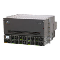
Vertiv NetSure 5100 Series Installation Manual (178 pages)
48 VDC Power System
Brand:
Vertiv
| Category:
Power Supply
| Size: 37.83 MB
Table of Contents
Table of Contents
3
Admonishments Used in this Document
6
Important Safety Instructions
7
Safety Admonishments Definitions
7
Safety and Regulatory Statements
7
Déclarations de Sécurité et de Réglementation
7
Customer Documentation Package
9
Installation Acceptance Checklist
10
Installing the System
12
General Requirements
12
Securing the Relay Rack to the Floor
12
Module Assembly
13
Mounting the System in a Relay Rack or an Equipment Rack
18
Mounting the Distribution Cabinet with Module Mounting Assembly(S)
18
Installing a List 93, 94 Battery Tray
24
Installing Optional 4-Post Flush Mounting Kit for Data Cabinets, P/N 559801
35
Changing Orientation of Load Return Busbars Located in a List 20, 21, 25, or 26 Distribution Cabinet
39
Installing Optional Lug Adapter Busbar Kits
41
Installing Circuit Breakers, Fuses, and Optional Transient Voltage Surge Suppressor (TVSS) Device(S)
42
Installation Instructions
50
Kit Description
50
Kit Contents
50
Tools and Material Required
52
Installation Procedure
52
Setting Jumper and Switch Options
65
Circuit Cards with Jumpers and Switches in a List 20, 21, 25, 26, 27 Distribution Cabinet
65
Jumper Settings on the System Interface Circuit Card
68
Switch Settings on the IB2 (Controller Interface Board)
69
Switch Settings on Optional EIB (Controller Extended Interface Board)
70
Switch Settings on the SM-DU (List 60 Hybrid Connection Cabinet)
71
Procedure
71
Making Electrical Connections
75
Important Safety Instructions
75
Wiring Considerations
75
Relay Rack / Equipment Cabinet Frame Grounding Connection
76
Power System Shelf Frame Grounding Requirements
77
Assemblies Comprising the Power System Frame Grounding Connection
78
Central Office Ground Connection
78
Rectifier Nominal 120 VAC / 208 VAC / 240 VAC Input and AC Input Equipment Grounding Connections
79
Wiring Considerations
79
To 19" or 23" Rectifier AC Input / Solar Converter DC Input Panel (List 40, 45) and 23" Rectifier AC Input Panel (List 46)
79
To Individual Module Mounting Assembly(S) Equipped with Molex Connectors and Provided with Rectifier AC Input Cable Assemblies or Rectifier AC Input Line Cords
85
Solar Converter 140 VDC to 200 VDC / 200 VDC to 400 VDC Input Connections
86
Wiring Considerations
86
To 19" or 23" Rectifier AC Input / Solar Converter DC Input Panel (List 40, 45)
86
To 23" Solar Connection Cabinet (List 61)
89
Solar Converter DC Input Cable Assemblies
89
48 VDC System Connections to an Optional List 60 Hybrid Connection Cabinet
92
Nominal 120 VAC Input and Equipment Grounding Connections to List 50, 51, 52, 53, 54, 55, 56, 57 Inverter
93
AC "Neutral" Reference Point (if Equipped with Optional Inverter System)
96
Nominal 120 VAC Output Connections (List 50, 51, 52, 53, 54, 55, 56, 57 Inverter Module Assembly)
97
List 50, 52, 54, 56 (Bulk Output)
97
List 51, 53, 55, 57 (NEMA Output)
97
External Alarm, Reference, Monitoring, and Control Connections
100
External Alarm, Reference, Monitoring, and Control Connection Locations
100
System Interface Circuit Card Connections (if Required)
103
RS485 Modbus Connection (if Required)
104
IB2 (Controller Interface Board) Connections (if Required)
104
Optional EIB (Controller Extended Interface Board) Connections (if Required)
113
Cabinet
119
Optional Customer Fuel Sensor Input
121
Connecting a Device or System to the NCU CAN Bus (if Required)
122
NCU Controller Ethernet Connection (if Required)
122
Control Bus Connections between Controller and Module Mounting Assemblies
125
Optional Transient Voltage Surge Suppressor (TVSS) Device Ground Connection
126
Load Connections
129
Load Connections to a List 20, 25 Distribution Cabinet
129
Load Connections to a List 21, 26 Distribution Cabinet
134
Load Connections to a List 27 Distribution Cabinet
145
Load Connections to an Optional GMT Fuse Block
148
Load Connections to a List KG Distribution Panel
149
Connections to an Optional List 60 Hybrid Connection Cabinet
150
Input Battery Connections
151
Input Battery Connections to List 20, 25 Distribution Cabinet
151
Input Battery Connections to List 21, 26 Distribution Cabinet
154
Input Battery Connections to List 27 Distribution Cabinet
158
Remote Distribution Unit (DU) Connections
158
List 27 Distribution Cabinet
158
Installing and Connecting Batteries in an Optional List 93 or 94 Battery Tray (if Furnished)
160
Important Safety Instructions
160
Installing the Modules
162
Installing Rectifier, Solar Converter, and Converter Modules
162
Installing Inverter Module in Inverter Module Mounting Assembly (if Equipped with Optional Inverter System)
167
Initially Starting, Configuring, and Checking System Operation
168
Important Safety Instructions
168
Initial Startup Preparation
168
Initially Starting the System
168
NCU Controller Initialization
169
Verifying and Setting the NCU Controller as Required for Your Application
170
Checking System Status
174
Final Steps
175
Advertisement
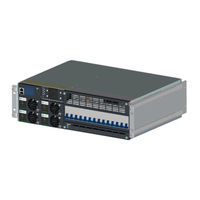
Vertiv NetSure 5100 Series Installation Manual (80 pages)
-48 VDC Power System
Brand:
Vertiv
| Category:
Power Supply
| Size: 7.75 MB
Table of Contents
Table of Contents
3
Admonishments Used in this Document
5
Important Safety Instructions
6
General Safety
6
Voltages
6
AC Input Voltages
6
DC Output and Battery Voltages
6
Battery
7
Personal Protective Equipment (PPE)
8
Hazardous Voltage
8
Handling Equipment Containing Static Sensitive Components
8
Maintenance and Replacement Procedures
8
Static Warning
9
Customer Documentation Package
11
Installation Acceptance Checklist
11
Installing the System
13
General Requirements
13
Securing the Relay Rack to the Floor (if Furnished)
13
Securing the System to a Relay Rack or a Cabinet Equipment Rack
15
(If Required)
15
Securing the System Vertically to a Wall with P/N 553203Kit
17
Furnished)
19
Securing the System Horizontally to a Wall with P/N 552537 or P/N
19
552535 Kit (if Furnished)
19
Installing a List 93, 94 Battery Tray
22
Installing Circuit Breakers and Fuses
25
Installing an Optional Battery Cabinet
27
Installing an Optional External IB4 Kit P/N 561929
28
Attaching the USB Drive Pouch to the System
29
Setting Jumper and Switch Options
30
Circuit Card Locations
30
Jumper Settings on the System Interface Circuit Card
31
Switch Settings on the IB2 (Controller Interface Board) (if Furnished)
33
Making Electrical Connections
35
Important Safety Instructions
35
Wiring Considerations
35
Relay Rack / Cabinet Frame Grounding Connection
35
System Shelves Frame Grounding Connection
36
Central Office Ground Connection
38
Rectifier Nominal 120 VAC / 208 VAC / 240 VAC Input and AC Input Equipment Grounding Connections
38
External Alarm, Reference, Monitoring, and Control Connections
41
Circuit Card Locations
41
RS-485 Connection (Used for Communication with SM Modules)
42
Temperature Probes
42
System Interface Circuit Card Connections (if Required)
42
IB2 (Controller Interface Board) Connections (if Furnished)
44
Connecting a Device or System to the NCU CAN Bus (if Required)
54
NCU Controller Ethernet Connection (if Required)
55
Control Bus Connections between Controller and System Shelves
57
Wiring
57
Load Distribution Wiring, Input Battery Wiring, and CO Ground Wiring
59
To List BF and NF
59
To List BC, LC, and NC
60
To List BA and NA
60
Load Distribution Wiring, Input Battery Wiring, and CO Ground Wiring
61
Load Distribution Wiring, Input Battery Wiring, and CO Ground Wiring
62
Connecting to an Optional Battery Cabinet
64
Installing and Connecting Batteries in an Optional List 93 or
64
Battery Tray (if Furnished)
64
Installing Rectifier Modules
67
Initially Starting, Configuring, and Checking System Operation
67
Initial Startup Preparation
67
Initially Starting the System
67
NCU Controller Initialization
67
Application
70
Checking System Status
79
Final Steps
79
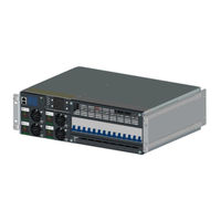
Vertiv NetSure 5100 Series User Manual (76 pages)
48 VDC Power System
Brand:
Vertiv
| Category:
Power Supply
| Size: 11.88 MB
Table of Contents
Table of Contents
3
Admonishments Used in this Document
5
Important Safety Instructions
6
Safety Admonishments Definitions
6
General Safety
6
Voltages
6
AC Input Voltages
6
DC Input Voltages
6
DC Output and Battery Voltages
7
Battery
7
Personal Protective Equipment (PPE)
8
Hazardous Voltage
8
Handling Equipment Containing Static Sensitive Components
9
Maintenance and Replacement Procedures
9
Static Warning
10
Customer Documentation Package
11
System Description
12
Operating Procedures
14
Controller
14
Solar Mode
14
ESTOP Function
14
Controller Battery Charge Current Limit Feature
15
Local Controls and Indicators
15
List 60 Hybrid Connection Cabinet
17
Maintenance
19
System Maintenance Procedures
19
Adding a Module to an Existing Module Mounting Assembly
19
Installing a Field Expansion Module Mounting Assembly
25
Installing Field Expansion Module Mounting Assembly Spacer Kit
26
P/N 560075
29
Reconfiguring a Dual Voltage Distribution Panel
31
DD, De)
31
Reconfiguring the Distribution Voltage on Positions 23 to 26 of a List DF Distribution Panel Installed in a List 27 Distribution Cabinet
39
Troubleshooting and Repair
44
Contact Information
44
Converters
44
Controller Configuration
44
System Troubleshooting Information
44
Replacement Information
46
Replacement Procedures
46
Replacing a Rectifier, Solar Converter, or -48 VDC to +24 VDC Converter Module
46
Replacing the NCU Controller
46
Replacing a Distribution Device
46
Circuit Card Replacement Procedures
50
Replacing a Distribution Panel in a List 20, 25 Distribution Cabinet
65
Replacing a Distribution Panel in a List 21, 26 Distribution Cabinet
68
Distribution Cabinet
71
Replacing a Battery or Load Disconnect Contactor in a List 21, 26 Distribution Cabinet
74
Advertisement
Vertiv NetSure 5100 Series User Manual (80 pages)
-48 VDC Power System
Brand:
Vertiv
| Category:
Power Supply
| Size: 17.72 MB
Table of Contents
Table of Contents
3
Admonishments Used in this Document
5
Important Safety Instructions
6
Safety Admonishments Definitions
6
Safety and Regulatory Statements
6
Déclarations de Sécurité Et de Réglementation
6
Customer Documentation Package
7
System Description
8
Operating Procedures
10
Controller
10
Solar Mode
10
ESTOP Function
11
EPO (Emergency Power Off) Function (if Equipped with Optional Inverter System)
11
Controller Battery Charge Current Limit Feature
12
Local Controls and Indicators
12
List 60 Hybrid Connection Cabinet
16
Maintenance
18
System Maintenance Procedures
18
Adding a Module to an Existing Module Mounting Assembly
18
Installing a Field Expansion Module Mounting Assembly
23
Installing Field Expansion Module Mounting Assembly Spacer Kit, P/N 560075
28
Adding an Inverter Module to an Existing Inverter Module Mounting Assembly
30
Reconfiguring a Dual Voltage Distribution Panel (List DA, DB, DC, DD, DE, FA, FB, FC, FD, FE)
32
Reconfiguring the Distribution Voltage on Positions 23 to 26 of a List DF Distribution Panel Installed in a List 27 Distribution Cabinet
38
Installing a Front Door Kit
43
Troubleshooting and Repair
45
Contact Information
45
Controller, Rectifiers, Solar Converters, Optional -48 VDC to +24 VDC Converters, Optional -48 VDC to -58 VDC Converters and Optional Inverters
45
Controller Configuration
45
System Troubleshooting Information
45
Replacement Information
47
Replacement Procedures
47
Replacing a Rectifier, Solar Converter, Optional -48 VDC to +24 VDC Converter, or Optional -48 VDC to -58 VDC Converter and Inverter
47
Replacing the NCU Controller
47
Replacing a Distribution Device
47
Circuit Card Replacement Procedures
51
Replacing a Distribution Panel in a List 20, 25 Distribution Cabinet
64
Replacing a Distribution Panel in a List 21, 26 Distribution Cabinet
67
Replacing a Battery or Load Disconnect Contactor in a List 20, 25 Distribution Cabinet
70
Replacing a Battery or Load Disconnect Contactor in a List 21, 26 Distribution Cabinet
73
Vertiv NetSure 5100 Series User Manual (72 pages)
-48 VDC Power System
Brand:
Vertiv
| Category:
Power Supply
| Size: 13.28 MB
Table of Contents
Table of Contents
3
Admonishments Used in this Document
4
Important Safety Instructions
5
Static Warning
8
Customer Documentation Package
9
System Description
10
Operating Procedures
11
Rectifiers, Solar Converters, -48 VDC to +24 VDC Converters, and Controller
11
Solar Mode
11
ESTOP Function
12
Controller Battery Charge Current Limit Feature
12
Local Controls and Indicators
12
List 60 Hybrid Connection Cabinet
14
Maintenance
16
System Maintenance Procedures
16
Adding a Module to an Existing Module Mounting Assembly
17
Installing a Field Expansion Module Mounting Assembly
21
Installing Field Expansion Module Mounting Assembly Spacer Kit, P/N 560075
25
Reconfiguring a Dual Voltage Distribution Panel (List DA, DB, DC, DD, DE)
27
Reconfiguring the Distribution Voltage on Positions 23 to 26 of a List DF Distribution Panel Installed in a List 27 Distribution Cabinet
33
Installing a Front Door Kit
38
Troubleshooting and Repair
40
Contact Information
40
Controller, Rectifiers, Solar Converters, and -48 VDC to +24 VDC Converters
40
Controller Configuration
40
System Troubleshooting Information
40
Replacement Information
42
Replacement Procedures
42
Replacing a Rectifier, Solar Converter, or -48 VDC to +24 VDC Converter Module
42
Replacing the NCU Controller
42
Replacing a Distribution Device
42
Circuit Card Replacement Procedures
46
Replacing a Distribution Panel in a List 20, 25 Distribution Cabinet
59
Replacing a Distribution Panel in a List 21, 26 Distribution Cabinet
62
Replacing a Battery or Load Disconnect Contactor in a List 20, 25 Distribution Cabinet
65
Replacing a Battery or Load Disconnect Contactor in a List 21, 26 Distribution Cabinet
68
Vertiv NetSure 5100 Series User Manual (30 pages)
48 VDC
Brand:
Vertiv
| Category:
Power Supply
| Size: 2.84 MB
Table of Contents
Table of Contents
3
Admonishments Used in this Document
4
Important Safety Instructions
5
General Safety
5
Voltages
5
AC Input Voltages
5
DC Output and Battery Voltages
5
Battery
6
Personal Protective Equipment (PPE)
7
Hazardous Voltage
7
Handling Equipment Containing Static Sensitive Components
7
Maintenance and Replacement Procedures
7
Static Warning
8
Customer Documentation Package
9
System Description
9
Operating Procedures
10
Controller and Rectifier
10
ESTOP Function
10
Controller Battery Charge Current Limit Feature
11
Local Controls and Indicators
11
Maintenance
11
System Maintenance Procedures
11
Adding a Rectifier
11
Installing a Field Expansion Rectifier Shelf
12
Troubleshooting and Repair
18
Contact Information
18
Controller and Rectifier
18
Controller Configuration
18
System Troubleshooting Information
18
Replacement Information
19
Replacement Procedures
19
Replacing a Rectifier
19
Replacing the NCU Controller
19
Replacing a Distribution Device
20
Circuit Card Replacement Procedures
22
Advertisement
Related Products
Vertiv NetSure 5000 Series
Vertiv NetSure-48 VDC Power System 502NGFB
Vertiv NetSure 7200 Series
Vertiv NetSure 7100 Compact
Vertiv NetSure ITS Series
Vertiv NetSure 802 Series
Vertiv Netsure
Vertiv NetSure SCC
Vertiv NetSure SM-DU+
Vertiv NetSure IPE Series
Vertiv Categories
UPS
Power Supply
Switch
Power distribution unit
Air Conditioner
More Vertiv Manuals
Login
Sign In
OR
Sign in with Facebook
Sign in with Google
Upload manual
Upload from disk
Upload from URL