Sign In
Upload
Manuals
Brands
Vertiv Manuals
Control Unit
Netsure
Vertiv Netsure Manuals
Manuals and User Guides for Vertiv Netsure. We have
4
Vertiv Netsure manuals available for free PDF download: User Manual, Installation Manual
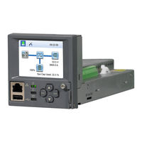
Vertiv Netsure User Manual (222 pages)
Brand:
Vertiv
| Category:
Control Unit
| Size: 8.68 MB
Table of Contents
Table of Contents
3
Admonishments Used in this Document
10
Introduction
11
Preface
11
Overview
11
Function Descriptions
12
Rectifier, Solar Converter, and Converter Control
12
System Components Monitoring and System Alarms Generation
12
Operating Data Acquisition and Data Logs
12
Battery Management
12
Battery Charge Temperature Compensation
13
Battery Equalize Charge and Battery Charge Current Limit
13
Battery Discharge Test and Battery Test Logs
14
Battery Thermal Runaway Management (BTRM) Feature
14
High and Low Battery Temperature Alarms
14
Battery Block and Battery Midpoint Monitoring
15
Battery Capacity Prediction
15
Battery LVD (Low Voltage Disconnect)
15
Enhanced Battery Monitoring with SM-BRC
15
Thermal Runaway Detection and Management
15
Energy Management
16
Energy Optimization Mode
16
Power Split Feature
16
Diesel Management Feature
17
Supervisory Module (SM Modules) Monitoring
17
Hybrid Control Function (Supporting Generator, Solar and Wind Energy Input, and Optimization)
17
General
17
Hybrid Operation
18
Early Termination of the Discharge Periods
19
Operation with Grid Power
19
Relay Assignment - When in Hybrid Mode
19
Capacity Discharge
20
Fixed Daily
20
Maximum Current Limit Function
20
Communications Function
21
FIAMM Sonick (Sodium Nickel) Battery Interface
21
Operation
22
Local Indicators
22
Passwords and Privilege Levels
23
Multiple Languages Supported
23
Using the Local Keypad and Display
24
Local Menu Navigation Keys and Local Display
24
Local Display Menus
24
Navigating the Menus
24
Using the Web Interface
25
Overview
25
Multiple Browsers Supported
25
Web Interface Screens
25
Procedures
25
Connecting the Controller to Your Local Area Network (LAN) When the System Is NOT Equipped with an IB4 Board
25
Setting for DHCP and Dhcpv6
25
Setting Ipv4 Communications Parameters (if Controller Not Set as DHCP)
25
Setting Ipv6 Communications Parameters (if Controller Not Set as Dhcpv6)
25
Connecting a Local Computer Directly to the Controller When the System Is NOT Equipped with an IB4 Board
26
Connecting the Controller to Your Local Area Network (LAN) When the System IS Equipped with an IB4 Board
26
Connecting a Local Computer Directly to the Controller When the System IS Equipped with an IB4 Board
27
Disabling Proxy Server Settings to Enable a Connection to the Controller over an Intranet Network (if Required)
27
Internet Security Settings for Loading Files or Downloading Files into the NCU
28
Logging into the Controller
29
Common Tasks Performed Via the Local Keypad And/Or Web Interface
30
Procedures
30
Start Wizard
30
Viewing Alarms
30
Viewing System Status
30
Blocking Alarms
31
Changing the Date and Time
31
Changing the Local LCD Display Orientation
31
Clearing Logs
31
Clearing or Resetting Alarms
31
Disabling the Local Keypad Sound
31
Viewing the NCU Controller's Device Inventory
31
Adding, Deleting, and Modifying Users
32
Setting Auto Equalize
32
Setting for DHCP and Dhcpv6
32
Setting IP Communications Parameters (if Controller Not Set as DHCP or Dhcpv6)
32
Setting SNMP Parameters
32
Setting TL1 Parameters
32
Programming the Audible Alarm Feature
33
Manually Forcing Lvds
33
Manually Forcing Relays
33
Assigning Severity Level to Alarms
33
Assigning Relays to Alarms
33
Placing the System in Float or Equalize Charge Mode
33
Viewing/Changing the Float Voltage Setting
33
Viewing/Changing the Equalize Voltage Setting
33
Setting Battery Parameters
34
Setting Battery Capacity Parameters
34
Setting Rectifier High Voltage Shutdown
34
Setting Solar Converter High Voltage Shutdown
34
Setting Rectifier Current Limit
34
Checking the Controller's Current Limit Point after Adding or Removing a Rectifier or Converter Module
34
Enabling Solar Mode
35
Setting over Voltage Alarm 1
35
Setting over Voltage Alarm 2
35
Setting under Voltage Alarm 1
35
Setting under Voltage Alarm 2
35
Setting Temperature Sensors
35
Setting Battery Charge Temperature Compensation
36
Setting Battery Thermal Runaway Management (BTRM) Feature
36
Configuring the NCU Identification of Rectifiers and Assigning Which Input Feed Is Connected to the Rectifiers
36
Configuring the NCU Identification of Solar Converters
37
Configuring the NCU Identification of Converters
37
Setting Digital Inputs
37
Setting Battery Block and Battery Midpoint Monitoring (if Equipped with an EIB Assembly)
37
Setting External Shunts (Connected to the EIB Assembly)
37
Setting External Shunts (Connected to the SM-DU+ Assembly)
38
Setting Shunts (Connected to the SM-DU Assembly)
38
Setting the System Current Alarm
38
Using the Relay Test Feature
38
Clearing the Maintenance Alarm
39
Performing a Manual Battery Discharge Test
39
Updating the NCU Controller's Device Inventory
39
Backing up the NCU Configuration
39
Reloading a Backed-Up NCU Configuration
40
Upgrading the NCU Using an Application ("All") Package
40
Restoring Factory Default Configuration
41
Rebooting the Controller
41
Changing the Names of Items Displayed in the LCD and Web-Interface Menus
41
Power Split Feature
42
How Power Split Works
42
Operating Modes
42
Overview
42
Paralleling the Existing and NCU Power Systems
43
Requirements and Conditions
43
Programming the NCU Power Split Feature
44
Verifying the Operation of the Power Split Feature
45
FIAMM Sonick (Sodium Nickel) Batteries Interface
46
FIAMM Battery Installation and User Instructions
46
FIAMM Battery Smcmonitor200 Software
46
Installation Requirements for NCU Monitoring of FIAMM Battery(S)
46
Required FIAMM Documentation
46
TL1 Interface
48
General
48
NCU TL1 Configuration
48
NCU TL1 Feature
48
NCU TL1 Port
48
Machine-To-Machine HTTP Interface
48
Description
48
Using the Machine-To-Machine HTTP Interface Option
48
Request
49
Response
49
Example
50
Request
50
Response
50
Resolving Alarms
51
Local Display Menus
80
Overview
80
Menus
80
Factory Default Setpoints
80
Adjustment Range Restrictions
80
Main Menu
82
Controller Information Menu (Accessed from the Main Menu)
83
Alarm Menu
84
Settings Menu
85
Start Wizard Sub-Menu (Accessed from Settings Menu)
90
Input Power Menu
91
Module Menu
92
DC Menu
93
Battery Menu
94
Description of Local Display Menus Programmable Parameters
96
Settings Menu
96
Maintenance Sub-Menu
96
Energy Saving Sub-Menu
96
Alarm Settings Sub-Menu
96
Rect Settings Sub-Menu
97
Batt Settings Sub-Menu
97
Basic Settings Sub-Menu
97
Charge Sub-Menu
97
Batt1 Settings Sub-Menu
98
Batt2 Settings Sub-Menu
98
Battery Test Sub-Menu
98
Temp Comp Sub-Menu
98
LVD Settings Sub-Menu
98
AC Settings Sub-Menu
99
Sys Settings Sub-Menu
99
Comm Settings Sub-Menu
99
Other Settings Sub-Menu
100
Web Interface Screens
103
Overview of Web Function
103
Homepage
103
System Status Information Area
105
System Specifications Information Area
105
Controller Specifications Information Area
105
Alarms Area
106
System Status Area
107
Power System Tab
107
Device Group Status Pages
108
General Status Tab
125
Menu Navigation Area
126
Settings Menu
126
Changing Programmable Parameters in the Settings Menu
128
Quick Settings Tab Programmable Parameter Descriptions
128
System Tab Programmable Parameter Descriptions
129
Battery Tab Programmable Parameter Descriptions
132
ECO Tab Programmable Parameter Descriptions
135
LVD Tab Programmable Parameter Descriptions
135
Temp Probes Tab Programmable Parameter Descriptions
136
Rectifiers Tab Programmable Parameter Descriptions
137
DC/DC Converters Tab Programmable Parameter Descriptions
138
Solar Tab Programmable Parameter Descriptions
139
Battery Test Tab Programmable Parameter Descriptions
140
Time Settings Tab Programmable Parameter Descriptions
141
History Log Menu
142
Alarm History Log Tab
142
Battery Test Log Tab
144
Event Log Tab
146
Data History Log Tab
148
System Log Tab
150
System Inventory Menu
152
Advanced Settings Menu
154
Ethernet Tab
154
Users Tab
155
SNMP Tab
157
Language Tab
160
SW Maintenance Tab
161
Alarms Tab
166
DI Alarms Tab
167
DO (Relay) Tab
169
Shunts Tab
171
Fuse Tab
174
Alarm Report Tab
176
Generator Tab
178
Power Split Tab
180
Monitor Protocol Tab
182
Clear Data Tab
187
TL1 AID Group Tab
188
TL1 AID Signal Tab
190
Accessing the Controller Via a Network Management System (NMS)
192
General
192
NMS Supported by SNMP Agent
192
NMS Supported by SNMP V2
192
NMS Supported by SNMP V3
192
Parameter Setting in SNMP Manager
193
MIB Installation
193
Installation
193
Contents of the Controller's MIB
193
Accessing the Controller through an NMS
193
Apply Administrative Privilege
193
Add NMS through Web Browser
193
ESR Configure
193
Accessing the NCU Via TL1
201
Accessing the TL1 Port
201
Port Connection
201
TL1 Port Connection Keep-Alive Feature
201
TL1 User Session
201
Establishing a Session
201
TL1 Autonomous Messages
201
TL1 Port Configuration
201
TL1 Commands, Autonomous Messages, and Error Codes Supported by the NCU
202
Format Overview of Required TL1 Messages
202
Samples
204
Table of TL1 Commands Supported
206
Expanded Description of TL1 Commands Supported (in Alphabetical Order)
207
Activate-User (Act-User)
207
Cancel-User (Canc-User)
208
Retrieve-Alarm (Rtrv-Alm-{Eqpt|All})
209
Retrieve Equipment (Rtrv-Eqpt)
212
Retrieve-Header (Rtrv-Hdr)
214
TL1 Autonomous Messages Supported (in Alphabetical Order)
215
Cancel Session (Timeout)
215
Report Alarm (Rept Alm {Eqpt/Com})
216
List of Error Codes for TL1 Commands Supported (in Alphabetical Order)
218
Replacement Procedures
219
NCU Replacement
219
NCU Digital Input and Relay Output Connections
220
NCU Digital Input Connections
220
NCU Relay Output Connections
220
IB2 (Controller Interface Board) and EIB (Controller Extended Interface Board)
220
Specifications
221
Advertisement
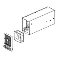
Vertiv Netsure User Manual (22 pages)
DC/DC Converter Module
Brand:
Vertiv
| Category:
Media Converter
| Size: 0.43 MB
Table of Contents
Table of Contents
3
Admonishments Used in this Document
4
Important Safety Instructions
5
General Safety
5
Voltages
5
DC Input Voltages
5
DC Output and Battery Voltages
5
Personal Protective Equipment (PPE)
6
Hazardous Voltage
6
Handling Equipment Containing Static Sensitive Components
6
Static Warning
7
Introduction
9
Overview
9
Specifications
9
DC Output Ratings
9
DC Input Ratings
9
Environmental Ratings
10
Compliance Information
11
Standard Features
11
Mechanical Specifications
14
Operation
15
Local Indicators
15
Converter High Voltage Shutdown and Lockout Restart
15
Installing Converter Modules
16
Troubleshooting and Repair
18
Troubleshooting
18
Converter Current Sharing Imbalanced
18
Converter Fault Symptoms and Troubleshooting
18
Replacement Procedures
20
Converter Module Replacement
20
Converter Fan Replacement
21
Vertiv Netsure User Manual (20 pages)
DC/DC Converter Module
Brand:
Vertiv
| Category:
Control Unit
| Size: 2.6 MB
Table of Contents
Table of Contents
3
Admonishments Used in this Document
4
Important Safety Instructions
5
Static Warning
6
Introduction
7
Overview
7
Specifications
7
DC Output Ratings
7
DC Input Ratings
9
Environmental Ratings
11
Compliance Information
11
Standard Features
12
Mechanical Specifications
13
Operation
13
Local Indicators
13
Converter High Voltage Shutdown and Lockout Restart
14
Converter Current Limit
14
Installing Converter Modules
15
Troubleshooting and Repair
16
Troubleshooting
16
Converter Module Current Sharing Imbalanced
16
Converter Module Fault Symptoms and Troubleshooting
16
Replacement Procedures
17
Converter Module Replacement
17
Advertisement
Vertiv Netsure Installation Manual (14 pages)
2nd Ethernet Port Add-On Kit
Brand:
Vertiv
| Category:
Controller
| Size: 2.95 MB
Table of Contents
Table of Contents
3
Admonishments Used in this Document
4
Important Safety Instructions
5
Safety Admonishments Definitions
5
Safety and Regulatory Statements
5
Déclarations de Sécurité et de Réglementation
5
Vertiv™ Netsure™ Control Unit (NCU) Controller 2Nd Ethernet Port Retrofit Kit
7
Kit Description
7
Kit Contents
8
Tools and Material Required
8
Installation Procedure
8
Vertiv™ Netsure™ Control Unit (NCU) Controller Second Ethernet Port Connection
11
Advertisement
Related Products
VERTIV NetSure Series
Vertiv Net Sure SM-DU+
Vertiv NetSure SM-DU+
Vertiv Netsure RDB Series
Vertiv NetSure 5100 Series
Vertiv NetSure-48 VDC Power System 502NGFB
Vertiv NetSure 7200 Series
Vertiv NetSure 7100 Compact
Vertiv NetSure ITS Series
Vertiv NetSure IPE Series
Vertiv Categories
UPS
Power Supply
Switch
Power distribution unit
Air Conditioner
More Vertiv Manuals
Login
Sign In
OR
Sign in with Facebook
Sign in with Google
Upload manual
Upload from disk
Upload from URL