Sign In
Upload
Manuals
Brands
Vanair Manuals
Power Supply
AIR N ARC VIPER 300 Series
Vanair AIR N ARC VIPER 300 Series Manuals
Manuals and User Guides for Vanair AIR N ARC VIPER 300 Series. We have
2
Vanair AIR N ARC VIPER 300 Series manuals available for free PDF download: Operations Manual & Parts List
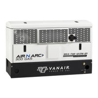
Vanair AIR N ARC VIPER 300 Series Operations Manual & Parts List (210 pages)
All-in-One Power Systems
Brand:
Vanair
| Category:
Power Supply
| Size: 13.31 MB
Table of Contents
Table of Contents
3
Glossary
11
General Terms and Definitions
11
Welding Terms and Definitions
11
Air Compressor Terms and Definitions
12
Warranty Claims Procedure
15
Claims Process for Warranted Parts
15
Procedure
15
Return Material Authorization Form
18
Introduction
19
Experience the Vanair Advantage
19
A Note on Manual Navigation
20
Section 1: Safety
21
General Information
21
Dangers, Warnings, Cautions, and Notes
21
International Safety Symbol
22
Arc Welding Hazards
22
Electrical Shock Can Kill
22
Build up of Gas Can Injure or Kill
24
Fumes and Gasses Can be Hazardsous
24
Arc Rays Can Burn Eyes and Skin
25
Enclosed Spaces Can Cause Abuild-Up of Noxious Fumes and Overheating
25
Welding Can Cause Fire and Explosion
25
Flying Metal Can Injure Eyes
26
Hot Parts Can Cause Severe Burns
27
Magnetic Fields Can Affect Pacemakers
27
Noise Can Damage Hearing
27
Section 1: Safety (Continued)
27
Cylinders Can Explode if Damaged
27
Engine Hazards
28
Battery Explosion Can Blind
28
Fuel Can Cause Fire or Explosion
28
Enclosed Spaces Can Cause Abuild-Up of Noxious Fumes and Overheating
29
Engine Exhaust Gases Can Kill
29
Hot Parts Can Cause Severe Burns
29
Moving Parts Can Cause Injury
29
Battery Acid Can Burn Skin and Eyes
30
Engine Heat Can Cause Fire
30
Exhaust Sparks Can Cause Fire
30
Compressed Air Hazards
30
Breathing Compressed Air Can Cause Seriouis Injury or Death
30
Enclosed Spaces Can Cause Abuild-Up of Noxious Fumes and Overheating
30
Compressed Air Can Cause Injury
31
Hot Metal from Air Arc Cutting and Gouging Can Cause Fire or Explosion
31
Hot Parts Can Cause Severe Burns
31
Read Instructions
31
Trapped Air Pressure and Whipping Hoses Can Cause Injury
31
Additional Symbols for Installation, Operation and Maintenance
32
Falling Unit Can Cause Injury
32
Flying Sparks Can Cause Injury
32
Overheating Can Damage Motors
32
Overuse Can Cause Overheating
32
Enclosed Spaces Can Cause Abuild-Up of Noxious Fumes and Overheating
33
Radiation Can Cause Interference
33
Read Instructions
33
Tilting of Trailer Can Cause Injury
33
Arc Welding Can Cause Interference
34
California Proposition 65 Warnings
34
Principal Safety Standards
35
Emf Information
36
Machine Canopy Access Safety Switches
36
Section 1: Safety (Continued)
36
Disposing of Machine Fluids
37
Section 2: Description
39
General Description
39
Compressed Air System
39
Compressor Unit
39
Electronic Inlet Valve
40
Air Inlet Filter
41
Minimum Pressure/Check Valve
41
Pressure Relief Valve
41
Secondary Spin-On Air/Oil Coalescer
41
Adjustable Pressure Switch
42
Oil Reservoir and Primary Air/Oil Separator
42
Oil Cooling System
42
Compressor Spin-On Oil Filter
44
Compressor Temperature and Pressure Switches
44
Engine
44
Ac Generator
46
Instrumentation
46
Volts/Amps Meter
47
Welder Function Switches
47
Ac Voltage Outlets
49
Battery Cable Receptacle
49
Circuit Breaker Overload Trip/Reset Buttons
49
Compressor Air Pressure Gauge
49
Compressor On/Off Toggle Switch
49
DC Charger Mode Toggle Switch
49
Generator Control On/Off Toggle Switch
49
Volts/Amps Manual Adjustment Dial
49
Welder Lead Junction
49
Alternator Fail Indicator Lamp
50
Door Open Indicator Lamp
50
Section 2: Description (Continued)
50
Engine Control (On/Off/Start) Switch
50
High Temperature Indicator Lamp
50
Low Oil Pressure Indicator Lamp
50
Preheat/Start Condition Indicator Lamp
50
Fuel Gauge/Hour Meter
50
Section 3: Specifications
51
Section 4: Installation
55
Machine Package Receipt/Inspection
55
Machine Package Prep
55
Service Body Prep
55
Machine Package Mounting
57
Installation and Dimensions Diagram (Part 1 of 2)
60
Installation and Dimensions Diagram (Part 2 of 2)
61
Section 5: Operation
63
General Information
63
Engine Start-Up and Shutdown Procedure
64
Engine Start-Up
64
Engine Shutdown
65
Engine Throttle Control Functions
66
Operating the Welder
66
CC (Constant Current) Mode
67
Welder Operating Procedure
67
CV (Constant Voltage) Mode - Using a Voltage Sensing Suitcase Feeder
69
CV (Constant Voltage) Mode - Usinga Spool Gun
69
Operating the Generator
71
Operating the Air Compressor
71
Operating the Battery Booster/Charger
72
Connection - Disconnection Sequence and Operation
73
Extreme Condition Operation
73
Cold Weather Operation
74
Engine Operation
74
Engine Operation
76
High Temperature Operation
76
Machine Operation
76
Engine Operation
77
High Dust Content Operation
77
Machine Operation
77
High Altitude Operation
78
Machine Operation
78
Section 6: Maintenance
79
General Information
79
Routine Maintenance Schedule
79
Maintenance Schedule Table
79
Replacement Parts
84
Maintenance Access
84
Parts Replacement and Adjustment Procedures
88
Caution
89
Compressor Air Filter
90
Compressor Air Filter Check
90
System Component or Part Group Task
90
Compressor Air Filter Inspection
91
Compressor Air Filter Replacement
91
Compressor Air Filter Replace- Ment
91
Repairing the Air Inlet Valve
92
Checking the Compressor Oil
94
Section 6: Maintenance (Continued)
95
Element
95
Changing the Compressor Oil
96
Replacing the Spin-On Air/Oil Coalescer
97
Replacing the Compressor Oil Filter
95
Replacing the Compressor Oil Filter Element
95
Coalescer
97
Part I - Removing the Compres
98
Parti - Removing the Compressor Serpentine Belt
98
Repairing the Compressor Shaft Seal
98
Part II - Accessing the Compres- Sor Unit Shaft Seal
100
Part II - Accessing the Compressor Unit Shaft Seal
100
Part III - Replacing the Compres- Sor Serpentine Belt
101
Part III - Replacing the Compressor Serpentine Belt
101
Replacing the Air Inlet Solenoid Valve
101
Before Mounting
103
Connecting the New Solenoid
103
Connecting the New Solenoid Valve
103
Solenoid Valve - Preparation before Mounting
103
Solenoid Valve-Preparation
103
Draining the Air Tank
104
Rebuilding the Minimum Pressure/Check Valve
106
Setting the Minimum Pressure Valve
106
Check Valve
106
Inspecting the System Coolers
107
Checking the Engine Oil
108
Adjusting the Engine Speed
110
Adjusting the Pressure Setting
110
Re-Tensioning the Air Compressor Serpentine Belt
111
Replacing and Re-Tensioning the Serpentine Drive Belts
111
Replacing the Air Compressor Serpentine Belt
113
Re-Tensioning the Generator Serpentine Belt
115
Replacing the Generator Serpentine Belt
116
Re-Tensioning the Engine Hydraulic Pump Drive Belt
118
Replacing the Engine Hydraulic Pump Drive Belt
119
Rebuilding the Minimum Pressure
106
Servicing the System Fuses and Circuit Breakers
120
Storage and Intermittent Use
120
Intermittent Use
120
Long Term Storage
120
Section 7: Troubleshooting
123
General Information
123
Troubleshooting Guide
124
Section 8: Diagrams
133
General Information
133
Wiring Diagram - Air N Arc 300 Series (Diesel)
134
Wiring Diagram - Switches & Lights
135
Trunk Line Assembly Harness
136
Compressor Flow Schematic Diagram
137
Section 9: Illustrated Parts List
139
Parts Ordering Procedure
139
Air N Arc 300 Systems Assemblies
142
Compressor and Parts Assembly (1 of 2)
144
Compressor and Parts Assembly (2 of 2)
148
Cooling System
150
Frame and Canopy (1 of 2)
154
Frame and Canopy (2 of 2)
158
Instrument Panel
162
Generators and Parts
166
Engine and Drive Parts (1 of 2)
168
Engine and Drive Parts (2 of 2)
174
Electrical System
180
Fuel Tank Assembly
182
Air Storage Assembly
184
Fuel Assembly - Without Fuel Tank
186
Decal and Plate Locations (1 of 4)
188
Decal and Plate Locations (2 of 4)
190
Decal and Plate Locations (3 of 4)
192
Decal and Plate Locations (4 of 4)
194
Appendix A: Additional Information
197
Electric Motor Chart - Starting Watts
197
Extension Cord Chart
198
Wattage Requirements for Common Receptacle Units
199
Appendix A: Additional Information (Cont.)
200
Air Tool Air Consumption Chart
200
Air N Arc 300 Series All-In-One Power System Available Options List
201
Hose Installation Guide
203
Electrode Ignition Procedure
204
Appendix B: Maintenance and Service Log
205
General Description
205
Maintenance and Service Log
206
Advertisement
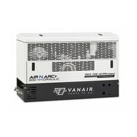
Vanair AIR N ARC VIPER 300 Series Operations Manual & Parts List (180 pages)
All-in-One Power Systems Hydraulic
Brand:
Vanair
| Category:
Power Supply
| Size: 9.84 MB
Table of Contents
Table of Contents
3
Glossary
11
General Terms and Definitions
11
Welding Terms and Definitions
11
Air Compressor Terms and Definitions
12
Warranty Claims Procedure
15
Claims Process for Warranted Parts
15
Procedure
15
Return Material Authorization Form
18
Introduction
19
Experience the Vanair Advantage
19
A Note on Manual Layout Navigation
20
Section 1: Safety
21
General Information
21
Dangers, Warnings, Cautions, and Notes
21
International Safety Symbol
22
Arc Welding Hazards
22
Electrical Shock Can Kill
22
Build up of Gas Can Injure or Kill
24
Fumes and Gasses Can be Hazardsous
24
Arc Rays Can Burn Eyes and Skin
25
Enclosed Spaces Can Cause Abuild-Up of Noxious Fumes and Overheating
25
Welding Can Cause Fire and Explosion
25
Flying Metal Can Injure Eyes
26
Hot Parts Can Cause Severe Burns
27
Magnetic Fields Can Affect Pacemakers
27
Noise Can Damage Hearing
27
Section 1: Safety (Continued)
27
Cylinders Can Explode if Damaged
27
Hydraulic Safety
28
Avoid High Pressure Fluids
28
Moving Parts Can Cause Injury
28
Enclosed Spaces Can Cause a Buiild-Up of Noxious Fumes and Overheating
29
Hot Parts Can Cause Severe Burns
29
Compressed Air Hazards
29
Breathing Compressed Air Can Cause Seriouis Injury or Death
29
Compressed Air Can Cause Injury
30
Enclosed Spaces Can Cause Abuild-Up of Noxious Fumes and Overheating
30
Hot Metal from Air Arc Cutting and Gouging Can Cause Fire or Explosion
30
Hot Parts Can Cause Severe Burns
30
Trapped Air Pressure and Whipping Hoses Can Cause Injury
30
Read Instructions
31
Additional Symbols for Installation, Operation and Maintenance
31
Falling Unit Can Cause Injury
31
Flying Sparks Can Cause Injury
31
Overheating Can Damage Motors
31
Enclosed Spaces Can Cause Abuild-Up of Noxious Fumes and Overheating
32
Overuse Can Cause Overheating
32
Radiation Can Cause Interference
32
Read Instructions
32
Tilting of Trailer Can Cause Injury
32
Arc Welding Can Cause Interference
33
California Proposition 65 Warnings
33
Principal Safety Standards
34
Emf Information
35
Machine Canopy Access Safety Switches
36
Disposing of Machine Fluids
36
Section 2: Description
38
General Description
39
Compressed Air System
39
Compressor Unit
39
Electronic Inlet Valve
40
Air Inlet Filter
41
Minimum Pressure/Check Valve
41
Pressure Relief Valve
41
Secondary Spin-On Air/Oil Coalescer
41
Adjustable Pressure Switch
42
Oil Reservoir and Primary Air/Oil Separator
42
Oil Cooling System
42
Compressor Spin-On Oil Filter
44
Compressor Temperature and Pressure Switches
44
Motor
44
Ac Generator
44
Instrumentation
45
DC Charger Mode Toggle Switch
46
Volts/Amps Manual Adjustment Dial
46
Volts/Amps Meter
46
Welder Function Switches
46
Battery Cable Receptacle
47
Compressor Air Pressure Gauge
47
Compressor On/Off Toggle Switch
47
Hz/Voltage Meter
47
Welder Lead Junction
47
Ac Voltage Outlets
49
Circuit Breaker Overload Trip/Reset Buttons
49
Compressor over Pressure Indicator Lamp
49
Compressor Overtemp Indicator Lamp
49
Front Access Panel Open Indicator Lamp
49
Generator Control On/Off Toggle Switch
49
Hydraulic Overtemp Indicator Lamp
50
Machine Control (Reset) Switch
50
Section 2: Description (Continued)
50
Hour Meter
50
Section 3: Specifications
51
Section 4: Installation
55
Machine Package Receipt/Inspection
55
Ana 300 Series All-In-One Machine Package Preparation
56
General Overview of Installation
56
Preparing the Vehicle Service Body
56
Determining Proper Ventilation Requirements
58
Machine Clearance Allowance
58
Roof Requirements (if Applicable)
58
Mounting the Machine
60
Marking the Machine Mounting Location
61
Separating the Machine from the Crate Mounting
61
Stabilizing Precautions for Machine Mounting
62
Grounding the Machine
63
Installing the Control Trunk Line
63
Installing the (Optional) Remote Control Panel
63
Installing the Remote Air Tank
63
Post-Set up Initial Test Function
64
Compressor Flow Schematic Diagram
66
Installation and Dimensions Diagram (Part 1 of 2)
67
Installation and Dimensions Diagram (Part 2 of 2)
68
Section 5: Operation (Continued)
71
Machine Start-Up and Shutdown Procedure
72
Machine Start-Up
72
Machine Shutdown
73
Motor Throttle Control Functions
74
Operating the Welder
74
CC (Constant Current) Mode
75
Welder Operating Procedure
75
CV (Constant Voltage) Mode - Using a Voltage Sensing Suitcase Feeder
77
CV (Constant Voltage) Mode - Usinga Spool Gun
77
Operating the Generator
78
Operating the Air Compressor
79
Operating the Battery Booster/Charger
80
Connection - Disconnection Sequence and Operation
80
Extreme Condition Operation
81
Cold Weather Operation
82
General Operation
82
High Temperature Operation
82
Machine Operation
82
High Altitude Operation
83
High Dust Content Operation
83
Machine Operation
83
Section 5: Operation
71
General Information
71
Section 6: Maintenance
85
General Information
85
Routine Maintenance Schedule
85
Maintenance Schedule Table
86
Replacement Parts
90
Maintenance Access
90
Parts Replacement and Adjustment Procedures Caution
91
Parts Replacement and Adjust- Ment Procedures
91
Compressor Air Filter
92
Compressor Air Filter Check
92
Parts Replacement and Adjustment Procedures
91
Section 6: Maintenance (Continued)
92
Compressor Air Filter Inspection
93
Compressor Air Filter Replacement
93
Compressor Air Filter Replace- Ment
93
Repairing the Air Inlet Valve
94
Checking the Compressor Oil
96
Replacing the Compressor Oil Filter Element
97
Replacing the Compressor Oil Filter
97
Element
97
Changing the Compressor Oil
98
Replacing the Spin-On Air/Oil Coalescer
99
Coalescer
99
Parti - Removing the Compressor Serpentine Belt
100
Repairing the Compressor Shaft Seal
100
Seal
100
Part I - Removing the Compres
100
Part II - Accessing the Compres- Sor Unit Shaft Seal
102
Part II - Accessing the Compressor Unit Shaft Seal
102
Part III - Replacing the Compres- Sor Serpentine Belt
103
Part III - Replacing the Compressor Serpentine Belt
103
Replacing the Air Inlet Solenoid Valve
103
Before Mounting
105
Connecting the New Solenoid
105
Connecting the New Solenoid Valve
105
Solenoid Valve - Preparation before Mounting
105
Solenoid Valve-Preparation
105
Valve
105
Draining the Air Tank
106
Rebuilding the Minimum Pressure/Check Valve
108
Setting the Minimum Pressure Valve
108
Rebuilding the Minimum Pressure
108
Check Valve
108
Setting the Minimum Pressure
108
Valve
108
Inspecting the System Coolers
109
Adjusting the Motor Speed
110
Adjusting the Pressure Setting
110
Re-Tensioning the Air Compressor Serpentine Drive Belt
112
Replacing and Re-Tensioning the Serpentine Drive Belts
112
Replacing the Air Compressor Serpentine Drive Belt
113
Re-Tensioning the Generator Serpentine Belt
114
Replacing the Generator Serpentine Drive Belt
115
Servicing the System Fuses and Circuit Breakers
117
Storage and Intermittent Use
117
Intermittent Use
117
Long Term Storage
117
Section 7: Troubleshooting
119
General Information
119
Troubleshooting Guide
120
Section 8: Diagrams
127
General Information
127
Wiring Diagram - Air N Arc 300 Series (Hydraulic)
128
Compressor Flow Schematic Diagram
129
Section 9: Illustrated Parts List
131
Parts Ordering Procedure
131
Air N Arc 300 Systems Assemblies
134
Compressor and Parts Assembly (1 of 2)
136
Compressor and Parts Assembly (2 of 2)
138
Cooling System
140
Cooling System - Compressor
142
Frame and Canopy
144
Instrument Panel (1 of 2)
146
Instrument Panel (2 of 2)
148
Generators and Parts
150
Motor Assembly
152
Air Storage Tank
154
Assembly Flow Control (1 of 2)
156
Assembly Flow Control (2 of 2)
158
Decal Locations (1 of 3)
160
Decal Locations (2 of 3)
162
Decal Locations (3 of 3)
164
Appendix A: Additional Information
167
Electric Motor Chart - Starting Watts
167
Extension Cord Chart
168
Wattage Requirements for Common Receptacle Units
169
Air Tool Air Consumption Chart
170
Air N Arc 300 Series All-In-One Power System Available Options List
171
Hose Installation Guide
173
Appendix B: Maintenance and Service Log
175
General Description
175
Maintenance and Service Log
176
Advertisement
Related Products
Vanair AIR N ARC VIPER 250 Series
Vanair AIR N ARC VIPER 150 Series
Vanair AIR N ARC RELIANT 300 Series
Vanair AIR N ARC POWERFLEX 300 Series
Vanair AIR N ARC CONTRACTOR 300 Series
Vanair AIR N ARC POWERFLEX 250 Series
Vanair AIR N ARC CONTRACTOR 250 Series
Vanair AIR N ARC POWERFLEX 150 Series
Vanair AIR N ARC CONTRACTOR 150 Series
Vanair AIR N ARC PRO 300 Series
Vanair Categories
Power Supply
Welding System
Remote Starter
Compressor
Air Compressor
More Vanair Manuals
Login
Sign In
OR
Sign in with Facebook
Sign in with Google
Upload manual
Upload from disk
Upload from URL