Sign In
Upload
Manuals
Brands
Themis Manuals
Server
RES-12DCX
Themis RES-12DCX Manuals
Manuals and User Guides for Themis RES-12DCX. We have
1
Themis RES-12DCX manual available for free PDF download: Installation Manual
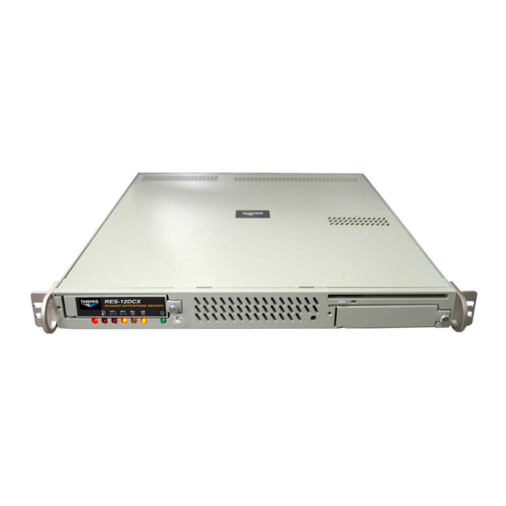
Themis RES-12DCX Installation Manual (144 pages)
Two Intel Dual-Core/Quad-Core 64-bit Xeon CPUs / 1RU Server /PCI-Express & PCI-X Slots / Gigabit Ethernet / Serial ATA (SATA)/Serial-Attached SCSI (SAS) / RAID / IDE-EIDE / Floppy / VGA / USB
Brand:
Themis
| Category:
Server
| Size: 3.31 MB
Table of Contents
Safety Instructions
6
Grounding Methods
8
Sicherheitshinweise
10
Table of Contents
13
Preface
25
Rugged Enterprise Server Model RES-12DCX
25
1 Overview and Specifications
29
Overview
29
Figure 1-1 RES-12DCX (with Rack Mounts)
29
Figure 1-2 RES-12DCX System Block Diagram
30
Figure 1-3 External Features of the RES-12DCX (Front and Rear)
31
Table 1-1 Major Features of the RES-12DCX
32
Figure 1-4 Major Components of the RES-12DCX (Open Top View)
34
Special Features
35
Environmental Temperature Control
35
Fan Status Monitor
35
Recovery from AC Power Loss
35
Voltage Monitors
35
CPU Fan Auto-Off in Sleep (Doze) Mode
36
CPU Overheat LED and Control
36
IPMI Module Support
36
System Resource Alert (Optional)
36
ACPI Features
36
External Modem Ring-On
37
Main Switch Override
37
Suspend-State Indicator
37
Wake-On-LAN (WOL)
37
Figure 1-5 RES-12DCX System Leds
38
System Leds
38
Table 1-2 System Leds
39
Chipset Overview
40
The Intel 5000P Memory Controller Hub (MCH)
40
The Intel 6321 ESB I/O Controller Hub (ICH)
41
The Intel 6700 PCI-X 64-Bit Hub (PXH-V)
41
Super I/O Controller
41
Specifications
43
General
43
Table 1-3 RES-12DCX General Specifications
43
Electrical
44
Output Voltage
44
System Power
44
Table 1-4 RES-12DCX Electrical Specifications
44
Environmental
45
Shock
45
Electrostatic Discharge
45
Noise Level
45
Table 1-5 Typical Noise Levels of the RES-12DCX
45
Packaging and Shipping
46
Rack-Mount Slides (Optional)
46
2 Installation and Operation
47
Installation Procedures
47
Remove Protective Top Cover
47
Figure 2-1 Remove the RES-12DCX Protective Access Cover
48
Memory Modules
49
Table 2-1 RES-12DCX Memory Modules
49
Table 2-2 Optimized DIMM Configurations
49
Figure 2-2 Memory Module Slot Location
50
Installation
50
Figure 2-3 Memory Module Removal
51
SATA-II Hard-Disk Drive
52
Disk-Drive Removal
52
Figure 2-4 RES-12DCX Hard-Disk Drive Removal
52
Disk-Drive Installation
53
PCI Cards
54
Figure 2-5 Positioning of the RES-12DCX PCI Riser Cards
54
Figure 2-6 PCI Riser Cards Are Attached to a Retainer Bracket
55
Figure 2-9 Remove the Blank Panel for each PCI Card to be Installed
56
Installation
57
Removable 38-MM Fan Housing
58
Figure 2-10 the RES-12DCX 38-MM Quadruple-Fan Housing
58
Removing the 38-MM Fan Housing
58
Figure 2-11 Release the Two Screws Securing the 38-MM Fan Housing
59
Installing a 38-MM Fan Housing
59
Lithium Battery
60
Figure 2-12 the RES-12DCX Lithium Battery and Socket
60
Installing a Lithium Battery
60
Removing the Lithium Battery
60
Rack Mounts
61
Mounting Brackets
61
Rack-Mount Slides (Optional)
61
Figure 2-13 Left Rack-Mount Bracket with a Handle
61
Operation
62
Plugging in the AC Power Cord
62
Turning the System on
62
Figure 2-14 AC Power Socket on the Rear of the RES-12DCX
62
Figure 2-15 System Power Switch and LED on the Front of the RES-12DCX
62
Getting Started
63
Configuration
63
Linux Installation
63
Turning the System off
63
Appendix A. Connector Pinouts
65
PS/2 Keyboard and Mouse
65
USB Port
66
Serial Port
67
Gigabit Ethernet LAN Port
68
Table A-4 Gigabit Ethernet Connector Pinout Signals and LED Interpretation
68
VGA Display Port
69
Table A-5 VGA Connector Pinout Signal Descriptions
69
SAS Port
70
Table A-6 SAS Connector Pinout Signal Descriptions
70
Figure A-6 SAS Status Leds on Motherboard
71
Appendix B. Rack-Mount Slide Installation
73
Figure B-1 Screw Locations for Rack-Mount Slides
73
Figure B-2 RES-12DCX Rack-Mount Slide Installation
75
Appendix C. BIOS Setup Utility
77
Introduction
77
System BIOS
77
How to Change the Configuration Data
78
Starting the Setup Utility
78
Running Setup
78
Main BIOS Setup
79
Figure C-1 the Main BIOS Setup Menu
79
Main Setup Features
80
BIOS Date
80
IDE Channel 0 Master/Slave, IDE Channel 1 Master/Slave
80
Legacy Diskette a
80
System Date
80
System Time
80
Native Mode Operation
81
Parallel ATA
81
SATA Controller Mode
81
Serial ATA
81
C.3.1.10System Memory
82
Extended Memory
82
Boot Features
83
Figure C-2 the Advanced BIOS Setup Menu
83
Quick Boot Mode
83
C.4 Advanced Setup
83
Quiet Boot Mode
84
POST Errors
84
ACPI Mode
84
Power Button Behavior
84
Resume on Modem Ring
84
Power Loss Control
84
Watch Dog
84
Summary Screen
84
Memory Cache
85
Cache System BIOS Area
85
Cache Video BIOS Area
85
Cache Base 0-512K
85
Cache Base 512K-640K
85
Cache Extended Memory
86
Discrete MTRR Allocation
86
PCI Configuration
86
Onboard Glan1/Onboard GLAN2 (Gigabit-LAN) OPROM Configure
86
Onboard SCSI OPROM Configure
86
PCI Parity Error Forwarding
87
Reset Configuration Data
87
Frequency for PCI-X #7, MASS (Mass Data Storage)/Zcr (Zero Channel RAID
87
Slot#6 PCI-X 133Mhz, Slot E1 X8, Slot E2 X4 and Slot E3 X8
87
Advanced Chipset Control
88
SERR Signal Condition
88
4GB PCI Hole Granularity
88
Memory Branch Mode
88
Branch 0 Rank Interleaving & Sparing
88
Branch 1 Rank Interleaving & Sparing
88
Enhanced X8 Detection
89
Crystal Beach Features
89
Route Port 80H Cycles
89
Clock Spectrum Feature
89
Enabling Multi-Media Timer
89
USB Function
89
Legacy USB Support
89
Advanced Processor Options
90
CPU Speed
90
Frequency Ratio (Only When Supported by the CPU
90
C1 Enhanced Mode (Only When Supported by the CPU
90
Core-Multi-Processing (Only When Supported by the CPU
90
Hyperthreading (Only When Supported by the CPU
90
Machine Checking (Only When Supported by the CPU
90
Thermal Management 2 (Only When Supported by the CPU
90
Adjacent Cache Line Prefetch (Only When Supported by the CPU
91
Execute Disable Bit (Only When Supported by the CPU
91
Hardware Prefetch (Only When Supported by the CPU
91
Intel Virtualization Technology (Only When Supported by the CPU
91
PECI Absent Alarm (Only When Supported by the CPU
91
Base I/O Address
92
I/O Device Configuration
92
Intel EIST Support (Only When Supported by the CPU
92
Interrupt
92
KBC Clock Input
92
Serial Port a
92
Base I/O Address
93
DMI Event Logging
93
Event Log Capacity
93
Event Log Validity
93
Floppy Disk Controller
93
Interrupt
93
Mode
93
Serial Port B
93
BAUD Rate
94
Clear All DMI Event Logs
94
COM Port Address
94
Console Redirection
94
Console Type
94
ECC Event Logging
94
Event Logging
94
Mark DMI Events as Read
94
View DMI Event Log
94
Console Connection
95
Continue CR after POST
95
Flow Control
95
Hardware Monitor Logic [Alternative 1
95
CPU Temperature Threshold
95
Fan Speed Control Modes
96
Voltage Monitoring
96
Hardware Monitor Logic [Alternative 2
97
C.4.10.1CPU Temperature Threshold
97
Fan Speed Control Modes
97
Voltage Monitoring
97
C.4.11.1 CPU Temperature Threshold
98
Temperature Monitoring (if Supported by the CPU
98
C.4.11.3Fan Speed Control Modes
99
Voltage Monitoring
99
IPMI (Only When an IPMI Card Is Installed
100
C.4.12.1IPMI Specification Version
100
Figure C-3 the Advanced BIOS Setup IPMI Submenu
100
Firmware Version
100
System Event Logging
100
BIOS POST Watch Dog
101
C.4.12.10Time out Option
101
C.4.12.4 Clear System Event Logging
101
Event Log Control
101
Existing Event Log Number
101
OS Boot Watch Dog
101
Timer for Loading os (Minutes
101
System Event Log/System Event Log (List Mode
102
Figure C-4 the System Event Log Submenu
102
Realtime Sensor Data
103
Figure C-5 the Realtime Sensor Data Submenu
103
Security Settings
104
Supervisor Password Is
104
Figure C-6 the BIOS Setup Security Submenu
104
User Password Is
105
Set Supervisor Password
105
Set User Password
105
Password on Boot
105
Boot Settings
106
Boot Priority Order/Excluded from Boot Orders
106
Figure C-7 the BIOS Setup Boot Submenu
106
Exit
107
Exit Saving Changes
107
Exit Discarding Changes
107
Figure C-8 the BIOS Setup Exit Submenu
107
Load Setup Defaults
108
Discard Changes
108
Save Changes
108
BIOS POST Messages
109
Appendix D. Red hat Enterprise Linux Installation
115
Introduction
115
Installation
115
BIOS Configuration
115
Installing from CD-ROM
115
Figure D-1 Language Selection
116
Language Selection
116
Figure D-2 Keyboard Selection
117
Keyboard Selection
117
Select Disk Partitioning Setup
117
Figure D-3 Disk Partitioning
118
Automatic Partitioning
119
Figure D-4 Automatic Partitioning
119
Partitioning Your System
120
Adding Partitions
121
Figure D-5 Disk Setup
121
Figure D-6 Add Partition
121
Boot Loader Configuration
123
Figure D-7 Boot Loader Configuration
123
Advanced Boot Loader Configuration
124
Figure D-8 Advanced Boot Loader Configuration
124
Figure D-9 Network Configuration
125
Network Configuration
125
Figure D-10 Editing a Network Device
126
D.2.2.10Firewall Configuration
127
Figure D-11 Firewall Configuration
127
Figure D-12 Time Zone Configuration
128
Figure D-13 Set Root Password
129
D.2.2.13 Package Group Selection
130
Figure D-14 Package Installation Defaults
130
Figure D-15 Package Group Selection
131
D.2.2.14 Preparing to Install
132
Figure D-16 Package Group Details
132
Installing Packages
132
D.2.2.16Installation Complete
133
Index
135
Reader Comment Card
144
Advertisement
Advertisement
Related Products
Themis RES-12XR3-S
Themis RES-11XR3
Themis RES-12XR3
Themis RES-XR4-1U
Themis RES-22DCX
Themis RES-22XR3
Themis RES-21XR3
Themis RES-22XR3-S
Themis RES-32DCX
Themis RES-XR4-3U
Themis Categories
Server
Barcode Reader
Motherboard
Laboratory Equipment
Video Card
More Themis Manuals
Login
Sign In
OR
Sign in with Facebook
Sign in with Google
Upload manual
Upload from disk
Upload from URL