Sign In
Upload
Manuals
Brands
Texas Instruments Manuals
Motherboard
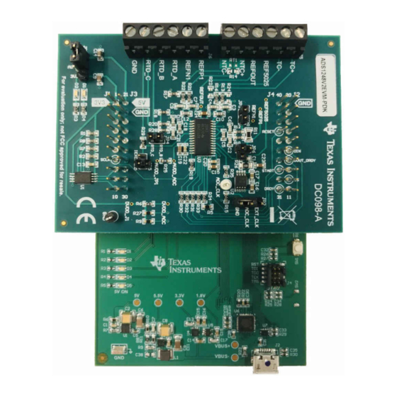
ADS1x48EVM
Texas Instruments ADS1x48EVM Module Manuals
Manuals and User Guides for Texas Instruments ADS1x48EVM Module. We have
1
Texas Instruments ADS1x48EVM Module manual available for free PDF download: User Manual
Texas Instruments ADS1x48EVM User Manual (48 pages)
Evaluation Modul
Brand:
Texas Instruments
| Category:
Motherboard
| Size: 2 MB
Table of Contents
Table of Contents
2
Introduction
5
Figure 1-1. Ads1X48Evm Functional Block Diagram
5
Table 1-1. Related Documentation
5
Getting Started with the Ads1X48Evm
6
Figure 2-1. Connecting the Ads1X48Evm to the PAMB
6
Ads1X48Evm Overview
7
Analog and Digital Power Supplies
7
Figure 3-1. LED Indicators D1 and D5
7
Figure 3-2. Jumper (JP1) Selects AVDD on the Ads1X48Evm
8
Voltage Reference Options
9
Figure 3-3. Ads1X48Evm VREF Options (Yellow) and Test Points (Red)
9
Table 3-1. Summary of Ads1X48Evm VREF Options
9
Clock Options
10
Figure 3-4. ADC Clock Options on the Ads1X48Evm
10
Digital Interface
11
Figure 3-5. Ads1X48Evm-To-Pamboard Connections
11
Table 3-2. Ads1X48Evm Header Pinout and Description
11
Analog Input Connections
12
Figure 3-6. Ads1X48Evm Analog Input Terminal Blocks
12
Table 3-3. Ads1X48Evm Terminal Block Input Description (J5 and J6)
12
Figure 3-7. Thermocouple Input Structure on the
13
Figure 3-8. Using REF5025 (Input J5:3) to Bias a Thermocouple
13
Figure 3-9. Thermistor Input Structure on the Ads1X48Evm
15
Figure 3-10. Connecting a Thermistor to the J5 Terminal Block on the
15
Figure 3-11. PCB Layout for J5 Terminal Block Showing Copper Pours for CJC Measurement
16
Figure 3-12. RTD Input Structure on the Ads1X48Evm
17
Table 3-4. Ads1X48Evm Terminal Block (J6) to ADC Connections
17
Figure 3-13. Connection Diagram for a 2-Wire RTD Using a Low-Side R
19
Figure 3-14. Connection Diagram for a 2-Wire RTD Using a High-Side R
20
Figure 3-15. Connection Diagram for a 3-Wire RTD Using One IDAC and a Low-Side R
21
Figure 3-16. Connection Diagram for a 3-Wire RTD Using One IDAC and a High-Side R
22
Figure 3-17. Connection Diagram for a 3-Wire RTD Using Two Idacs and a Low-Side R
23
Figure 3-18. Connection Diagram for a 3-Wire RTD Using Two Idacs and a High-Side R
24
Figure 3-19. Connection Diagram for a 4-Wire RTD Using a Low-Side R
25
Figure 3-20. Connection Diagram for a 4-Wire RTD Using a High-Side R
26
Table 3-5. Ads1X48Evm Settings for Different RTD Types
26
Figure 3-21. Using the TC± Inputs on J5 as General-Purpose Signal
27
Ads1X48Evm GUI
28
Home
28
Figure 4-1. Browser Extension and TI Cloud Agent Installation
28
Figure 4-2. Ads1X48Evm GUI Home Page
29
Figure 4-3. Connected Hardware Information
29
Figure 4-4. File Menu
30
Data Capture
31
Figure 4-5. Data Capture Window
31
Figure 4-6. Capture Settings Slide-Out
31
Figure 4-7. Capture Statistics
32
Figure 4-8. Time Domain Plot
32
Register Map
33
Figure 4-9. Histogram Plot
33
Figure 4-10. Register Map
34
Figure 4-11. Register Read and Write Controls
34
Figure 4-12. Auto Read Options
35
Figure 4-13. Register Write Options
35
Bill of Materials, Printed Circuit Board Layout, and Schematic
36
Bill of Materials
36
Table 5-1. Bill of Materials
36
Printed Circuit Board Layout
38
Figure 5-1. Composite PCB Layout
38
Figure 5-2. Top Silkscreen
39
Figure 5-3. Top Layer
39
Figure 5-4. Internal Ground Layer 1
39
Figure 5-5. Internal Ground Layer 2
39
Figure 5-6. Bottom Layer
40
Figure 5-7. Bottom Silkscreen
40
Schematic
41
Figure 5-8. Ads1X48Evm Schematic
41
Revision History
42
Advertisement
Advertisement
Related Products
Texas Instruments ADS1x9xECG-FE
Texas Instruments ADS1x20EVM
Texas Instruments ADS1281EVM
Texas Instruments ADS1194
Texas Instruments ADS1015EVM
Texas Instruments ADS1241
Texas Instruments ADS1120EVM
Texas Instruments ADS131E08
Texas Instruments ADS1258EVM
Texas Instruments ADS126xEVM-PDK
Texas Instruments Categories
Motherboard
Control Unit
Microcontrollers
Computer Hardware
Calculator
More Texas Instruments Manuals
Login
Sign In
OR
Sign in with Facebook
Sign in with Google
Upload manual
Upload from disk
Upload from URL