Sign In
Upload
Manuals
Brands
Tektronix Manuals
Measuring Instruments
WCA230A
Tektronix WCA230A Manuals
Manuals and User Guides for Tektronix WCA230A. We have
5
Tektronix WCA230A manuals available for free PDF download: Programmer's Manual, User Manual, Service Manual, Instructions Manual
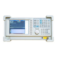
Tektronix WCA230A Programmer's Manual (678 pages)
3 GHz & 8 GHz Portable Wireless Communication Analyzers
Brand:
Tektronix
| Category:
Measuring Instruments
| Size: 1 MB
Table of Contents
Table of Contents
3
Preface
11
Related Manual
11
Difference between WCA230A and WCA280A
11
Getting Started
13
Overview of the Manual
16
Figure 1- 1: Command Parts
16
Figure 1- -2: Functional Groupings and an Alphabetical List of
16
Figure 1- 3: Event-Driven Program
17
Figure 1- 4: Sample Program (Visual C++ Source Code)
17
Connecting the Interface
18
Figure 1- 5: GPIB Connector (Rear Panel)
18
Using the GPIB Port
19
Figure 1- 6: GPIB Connection
19
Figure 1- 7: Typical GPIB Network Configurations
19
Setting the GPIB Parameters from the Front Panel
20
Figure 1- 8: Remote Setup Menu
20
Figure 1- 9: Setting the GPIB Parameters
21
Using Tekvisa
22
Syntax and Commands
25
Command Syntax
27
Backus-Naur Form Definition
27
Table 2- 1: BNF Symbols and Meanings
27
SCPI Commands and Queries
28
Figure 2- 1: Example of SCPI Subsystem Hierarchy Tree
28
Table 2- 2: Query Response Examples
29
Table 2- 3: Parameter Types Used in Syntax Descriptions
30
Figure 2- 2: Example of Abbreviating a Command
32
Figure 2- 3: Example of Chaining Commands and Queries
33
Figure 2- 4: Example of Omitting Root and Lower-Level Nodes in a Chained Message
33
Table 2- 4: Available Units
34
Table 2- 5: Available si Prefixes
34
IEEE 488.2 Common Commands
36
Constructed Mnemonics
36
Table 2- 6: Constructed Mnemonics
36
Command Groups
37
Measurement Mode
38
Table 2- 7: Measurement Mode
38
Functional Groups
39
Table 2- 8: List of Command Groups
39
IEEE Common Commands
40
Abort Commands
40
Table 2- 9: IEEE Common Commands
40
Table 2- 10: :Abort Commands
40
Calculate Commands
41
Table 2- 11: :Calculate Commands
41
Calibration Commands
42
Configure Commands
42
Table 2- 12: :Calibration Commands
42
Table 2- 13: :Configure Commands
42
Display Commands
43
Fetch Commands
50
Table 2- 15: :Fetch Commands
50
Format Commands
51
Table 2- 16: :Format Commands
51
Hcopy Commands
52
Initiate Commands
52
Input Commands
52
Table 2- 17: :Hcopy Commands
52
Table 2- 18: :Initiate Commands
52
Table 2- 19: :Input Commands
52
Instrument Commands
53
Mmemory Commands
53
Table 2- 20: :Instrument Commands
53
Table 2- 21: :Mmemory Commands
53
Program Commands
54
READ Commands
54
Table 2- 22: :Program Commands
54
Table 2- 23: :READ Commands
54
Sense Commands
55
Table 2- 24: :Sense Commands
55
Status Commands
62
System Commands
62
Table 2- 25: :Status Commands
62
Table 2- 26: :System Commands
62
Trace Commands
63
Trigger Commands
63
Table 2- 27: :Trace Commands
63
Table 2- 28: :Trigger Commands
63
UNIT Commands
64
Table 2- 29: :UNIT Commands
64
Calculate Commands 2
77
Figure 2- 5: View Number Assignments
77
Calibration Commands 2
93
Configure Commands 2
101
IEEE Common Commands 2
65
Abort Commands 2
75
Table 2- 30: :Display Command Subgroups
115
Display Commands 2
115
Figure 2- 6: Horizontal Scale Setting Requirements
116
Figure 2- -7: Horizontal Scale Setting Requirements for Spectrum
117
Table 2- -14: :Display Commands
117
Figure 2- 8: :Display:ccdf Command Setting
118
Figure 2- 9: :Display:ddemod Command Setting
126
Table 2- 31: Main View Display Formats
129
Table 2- 32: Subview Display Formats
143
Figure 2- 10: :Display:oview Command Setting
154
Table 2- 33: Subview Display Format
172
Figure 2- 11: :Display:pulse:spectrum Command Setting
176
View
177
Table 2- 34: Subview Display Formats
196
Figure 2- 12: :Display:spectrum Command Setting
212
Table 2- -35: Subview Display Formats in the Signal Source Analysis . 2
232
Figure 2- 13: :Display:tfrequency Command Setting
255
Figure 2- 14: View Display Formats
265
Figure 2- 16: Setting up the ACPR Measurement
400
Figure 2- 17: Defining the Analysis Range
403
Table 2- -48: Measurement Item Selections 2
408
Table 2- -49: Block Size Setting Range 2
413
Figure 2- 18: Setting up the Channel Power Measurement
419
Figure 2- 19: Setting up the C/N Measurement
422
Figure 2- 20: Defining the Analysis Range
432
Table 2- -50: Modulation Selections 2
439
Table 2- -51: Communication Standard Selections 2
448
Figure 2- 21: Setting up the EBW Measurement
451
Figure 2- 22: Setting Frequency and Span
453
Table 2- -52: Measurement Frequency Bands 2
454
Table 2- -53: Span Setting 2
460
Figure 2- 23: Setting up the OBW Measurement
463
Table 2- -54: RFID Measurement Items 2
483
Table 2- -55: Decoding Format 2
489
Table 2- -56: Modulation Format 2
490
Table 2- -57: RFID Demodulation Standard 2
494
Table 2- -58: FFT Windows 2
515
Table 2- -59: S/A Mode Measurement Items 2
517
Figure 2- -24: Setting up the Spurious Signal Measurement 2
522
Table 2- -60: Analysis Length Setting Range 2
537
Table 2- -61: Ssource Measurement Items 2
538
Figure 2- -25: Defining the Analysis Range 2
550
Status Commands 2
555
System Commands 2
563
Trace Commands 2
573
Trigger Commands 2
579
Table 2- -62: bin Number Setting Range 2
582
Figure 2- -26: Trigger Mask Setting Example 2
583
UNIT Commands 2
595
Retrieving Response Message 2
597
Status and Event Reporting System 3
601
Registers 3
602
Enable Registers 3
603
Transition Registers 3
604
Queues 3
605
Figure 2- 15: :Display:waveform Command Setting
266
Fetch Commands 2
271
Results 2
280
Table 2- -37: Queried Information 2
287
Table 2- -38: RFID Measurement Selections 2
294
Table 2- -39: Symbol Value Definition 2
297
Table 2- -40: Signal Source Analysis 2
309
Format Commands 2
321
Hcopy Commands 2
323
Initiate Commands 2
327
Input Commands 2
331
Table 2- -41: Input Attenuation Settings 2
332
Table 2- -42: Mixer Level Settings 2
335
Table 2- -43: Reference Level Range 2
336
Instrument Commands 2
337
Table 2- -44: Measurement Mode 2
338
Mmemory Commands 2
341
Program Commands 2
351
READ Commands 2
357
Table 2- -45: Queried Information on the Digital Modulation Analysis Results 2
366
Table 2- -46: Signal Source Analysis 2
389
Sense Commands 2
397
Enable Registers
609
Status and Event Processing Sequence 3
613
Synchronizing Execution 3
614
Error Messages and Codes 3
617
Command Errors 3
618
Execution Errors 3
620
Device Specific Errors 3
622
General Programming Procedure 4
625
Application Program Sample 4
627
Macro Program Execution Sample 4
639
Appendix A: Character Charts
643
Appendix B: GPIB Interface Specification
645
Interface Messages
646
Appendix C: Factory Initialization Settings
649
Appendix D: Setting Range
661
Appendix E: SCPI Conformance Information
665
Advertisement
Tektronix WCA230A User Manual (454 pages)
3 GHz & 8 GHz Portable Wireless Communication Analyzers
Brand:
Tektronix
| Category:
Measuring Instruments
| Size: 6 MB
Table of Contents
Table of Contents
9
Figure 2- -11: Menu Keys
20
List of Tables
21
General Safety Summary
23
About this Manual
25
Preface
25
Related Documents
26
Conventions
27
Notice for Trigger Function
28
Getting Started
29
Features
31
Product Overview
31
Application
32
Difference between WCA230A and WCA280A
32
Figure 1- 1: Concept of the Swept Spectrum Analyzer
33
Figure 1- 2: Sweep of Resolution Filter
33
Real-Time Analysis
33
Figure 1- 3: Concept of the Real-Time Spectrum Analyzer
34
Figure 1- 4: Concurrent Acquisition
34
Figure 1- 5: Frame Acquisition
35
Architecture
36
Figure 1- 6: Block Diagram
36
Installation
39
Unpacking to Check Contents
39
Applying Power
40
Figure 1- 7: AC Input (Rear Panel)
40
Figure 1- 8: Principal Power Switch (Rear Panel)
41
Figure 1- 9: Front Panel Power Switch (ON/STANDBY Switch)
41
Figure 1- 10: Initial Screen
42
Figure 1- 11: RF INPUT Connector
42
Figure 1- 12: Setting up the Stand
43
Setting up the Stand
43
Figure 1- 13: Spectrum of the Calibration Signal (50 Mhz, about - 20 Dbm)
44
Functional Check
44
Figure 1- 14: Setup Display
45
Table 1- 1: Span and RBW
45
Figure 1- 15: Reference Level Setting and A/D Overflow Indicator
46
Figure 1- 16: Spectrogram Display
47
Powering off the Analyzer
48
Restart
49
About Installation of Other Applications
50
Backing up User Files
50
Calibration
51
Cal Menu
52
Figure 1- 17: Calibration Menu Structure
52
Calibrating Gain
53
Figure 1- 18: UNCAL Display
53
Calibrating Center Offset
54
Figure 1- 19: Center Offset
54
Calibrating DC Offset
55
Figure 1- 20: DC Offset
55
Adjusting Display Brightness
56
Confirming Performance
56
Figure 1- 21: System Menu
56
Operating Basics
57
Interface Maps
59
Controls and Connectors
60
Figure 2- 1: Front Panel
60
Figure 2- 2: Rear Panel
62
Figure 2- 3: Side Panel
63
Figure 2- 4: Connecting USB Devices
64
Figure 2- 5: Operation with Mouse and Keyboard
65
Table 2- 1: Key Functions of the Keyboard
65
Display Screen
66
Figure 2- 6: Display Screen Configuration
66
Figure 2- 7: Status Display
68
Figure 2- 8: Pre- and Post-Trigger Regions
68
Table 2- 2: Status Display
68
Figure 2- 9: Key Lock Display
69
Figure 2- 10: Setup Display
70
Table 2- 3: Setup Display
70
Functional Overview
71
Menu Keys
71
Table 2- 4: Menu Key Summary
72
Figure 2- 12: Example Menu Item Display
74
Menu Operations
74
Measurement Basics
79
Table 2- 5: Measurement Modes
79
Setting System Parameters
81
Using Windows XP
84
Tutorial
87
Preparations
88
Displaying Spectrum
92
Using Markers and Peak Search
101
Using Averaging and Comparison Displays
107
Displaying a Spectrogram
110
Spectrum Analysis
113
Modulation Analysis
117
Turning off the Power
124
Reference
125
Spectrum Analysis (S/A Mode)
127
Table 3- 1: Standard Menu in the S/A Mode
127
Measurement Screen Layout
128
Spectrum Analysis
130
Table 3- 2: Measurement Items in the S/A Mode
130
Spectrogram Display
144
Real-Time Analysis
146
Table 3- 3: Features of the Real-Time Mode
147
Table 3- 4: Span Setting Range
147
Zoom Function
150
Modulation Analysis (Demod Mode)
153
Table 3- 5: Standard Menu in the Demod Mode
154
Measurement Screen Layout
155
Analog Modulation Analysis
163
Digital Modulation Analysis
170
Table 3- 6: Communication Standard and Parameters
171
Table 3- 7: Modulation Type and Available Measurement Item
171
RFID Analysis
187
Table 3- 8: Measurement Items for RFID Analysis
188
Table 3- 9: Standard Settings
195
Table 3- 10: Details of the RF Envelope Measurement Table
202
Table 3- 11: Symbol Value Definition
206
Table 3- 12: Measurement Result Display Items
206
Measurement Screen Layout
209
Time Analysis (Time Mode)
209
Time Variation Measurement
210
CCDF Measurement
214
Pulse Measurements
219
Signal Source Analysis
229
Table 3- 13: Signal Source Measurement Items
229
Table 3- 14: Phase Noise Measurement Frequency Band
234
Table 3- 15: bin Width for each Decade
234
Table 3- 16: the Number of Waveform Points
235
Setting Frequency and Span
245
Frequency and Span Setting Menu
246
Using the Channel Table
248
Using the Marker and Peak Search
249
Frequency Setting Range
250
Table 3- 17: Frequency and Span Setting Range
250
Vector Span
252
Amplitude Menu
253
Setting Amplitude
253
Table 3- 18: Reference Level Setting Range
254
Table 3- 19: RF Attenuation Level Setting
255
Table 3- 20: Mixer Level Setting
255
Table 3- 21: Vertical Scale Setting Range
256
Over-Voltage Input
257
Amplitude Correction
258
Setting Timing Parameters
267
Timing Menu
267
Seamless Acquisition
271
Trigger
273
Trigger Menu (S/N B020000 and Above)
274
Table 3- 22: How to Acquire a Waveform
275
Table 3- 23: Trigger Level Setting Range
277
Trigger Menu (S/N below B020000 and J300100 and Above)
281
Table 3- 24: How to Acquire a Waveform
282
Table 3- 25: Trigger Level Setting Range
283
IF Trigger (S/N below B020000 and J300100 and Above)
288
Creating a Trigger Mask (Option 02 Only)
291
Trigger Point Indicator
297
Synchronous Operation with External Instruments
298
FFT and RBW
299
RBW/FFT Menu
300
FFT Points
303
FFT Window
304
Table 3- 26: Characteristics and Usage of FFT Windows
304
Table 3- 27: FFT Window and Bandpass Filter
306
Trace Comparison Display and Average Function
309
Trace/Avg Menu
310
Table 3- 28: Averaging Method
311
Displaying Trace 1 and 2
312
Averaging the Waveform
313
Saving/Loading Waveform Data
316
Trace Compression
316
Setting Views
319
View Menu
320
Basic Procedure
321
Spectrum View Setting
322
Spectrogram View Setting
323
Time Domain View Setting
325
CCDF View Setting
327
Constellation View Setting
328
EVM View Setting
329
Eye Diagram Setting
332
Symbol Table Setting
332
AM/AM View Setting
334
AM/PM View Setting
335
PDF View Setting
336
Noisogram View Setting
337
Display Line
339
Display Line Operation (Other than Real Time S/A)
340
Multi Display Lines (Real Time S/A Only)
343
Marker Operation and Peak Search
347
Markers Menu
348
Using Markers
351
Peak Search
356
Displaying the Online Help
359
Using the Online Help
359
Using a Mouse and Keyboard
362
Input Menu
363
Selecting Input Source
363
File Operations
365
Load/Save Menu
366
Saving and Loading Files
368
Entering a File Name
374
Deleting a File
376
Making/Deleting a Directory
376
Data File Format
377
File Format
377
Trace File Format
385
Tektronix WCA230A Service Manual (332 pages)
Portable Wireless Communication Analyzer
Brand:
Tektronix
| Category:
Measuring Instruments
| Size: 5 MB
Table of Contents
Contacting Tektronix
2
Warranty
3
Table of Contents
5
Figure 1-6: Block Diagram
11
Table 2-2: Power Cord Identification
13
General Safety Summary
15
Service Safety Summary
17
Preface
19
Manual Structure
19
Manual Conventions
20
Finding Other Information
20
Introduction
21
Performance Check Interval
21
Strategy for Servicing
21
Specifications
23
Product Overview
25
Features
25
Application
26
Difference between WCA230A and WCA280A
26
Real-Time Analysis
27
Figure 1-1: Concept of the Swept Spectrum Analyzer
27
Figure 1-2: Sweep of Resolution Filter
27
Figure 1-3: Concept of the Real-Time Spectrum Analyzer
28
Figure 1-4: Concurrent Acquisition
28
Figure 1-5: Frame Acquisition
29
Architecture
30
Down Converter
31
Specifications
33
Performance Conditions
33
Electrical Characteristics
34
Table 1-1: Frequency
34
Table 1-2: Spectrum Purity
34
Table 1-3: Noise Sideband
35
Table 1-4: Input
36
Table 1-5: Amplitude
36
Table 1-6: Dynamic Range
37
Table 1-7: Spurious Response
38
Table 1-8: Acquisition
39
Table 1-9: Sampling Rate
39
Table 1-10: Frame Time
40
Table 1-11: Digital Demodulation
40
Table 1-12: Analog Demodulation
42
Table 1-13: RBW (Resolution Bandwidth)
43
Table 1-14: Trigger
44
Table 1-15: Measurement Function
44
Table 1-16: Display
45
Table 1-17: Marker, Trace, and Display Line
45
Table 1-18: Controller and Interface
45
Table 1-19: Power Requirements
46
Table 1-20: Power Connector
46
Physical Characteristics
47
Environmental Characteristics
47
Table 1-21: Physical Characteristics
47
Table 1-22: Environmental Characteristics
47
Table 1-23: Certifications and Compliances
48
Operating Information
51
Installation
53
Supplying Operating Power
53
Table 2-1: Power-Cord Conductor Identification
53
Operating Voltage
54
Operating Environment
55
Ventilation Requirements
55
Applying Power
56
Figure 2-1: AC Input (Rear Panel)
56
Figure 2-2: Principal Power Switch (Rear Panel)
57
Figure 2-3: Front Panel Power Switch (ON/STANDBY Switch)
57
Figure 2-4: Initial Screen
58
Figure 2-5: RF INPUT Connector
58
Powering off the Analyzer
59
Restart
60
Setting up the Stand
61
Figure 2-6: Setting up the Stand
61
Repackaging Instructions
62
Installed Options
62
Operating Instructions
63
Preparations
64
Figure 2-7: Cable Connection
64
Figure 2-8: Principal Power Switch (Rear Panel)
65
Figure 2-9: Power Switch (ON/STANDBY)
65
Figure 2-10: Initial Screen
66
Displaying Spectrum
68
Figure 2-11: Frequency, Span, and Amplitude Settings
68
Figure 2-12: Menu Items for Numeric Value Input
69
Figure 2-13: Numeric Value Entry Keypad
70
Figure 2-14: Center Frequency of 800 Mhz, Span of 15 Mhz
70
Figure 2-15: Center Frequency of 800 Mhz, Span of 100 Khz
72
Figure 2-16: Setting Amplitude
73
Figure 2-17: Menu Items for Numeric Value Input
74
Figure 2-18: Reference Level of 10 Dbm
74
Figure 2-19: Status Indicator
75
Using Markers and Peak Search
77
Figure 2-20: Measurement with a Single Marker
78
Figure 2-21: Measurement with the Delta Marker
80
Figure 2-22: Searching for the Peak
82
Using Averaging and Comparison Displays
83
Figure 2-23: Comparing a New Waveform with an Averaged Waveform
84
Figure 2-24: Comparison Display with Averaged Waveform
85
Displaying a Spectrogram
86
Figure 2-25: Concurrent Display of Spectrum and Spectrogram
86
Figure 2-26: Tall Display of Spectrum and Spectrogram
87
Figure 2-27: Spectrogram View
88
Spectrum Analysis
89
Modulation Analysis
93
Setting the Acquisition
96
Using Windows XP
100
Turning off the Power
102
Theory of Operation
103
RF Input Circuit
105
Power Supply Circuit
109
Performance Verification
111
Brief Procedures
115
Functional Check
116
Table 4-1: Span and RBW
118
Table 4-2: Internal Diagnostic Program
120
Performance Tests
121
Equipment Required
122
Table 4-3: Test Equipment
122
Auto Tests
124
Manual Tests
132
Input Attenuator Setting
138
Table 4-4: Spurious Measurement
152
Test Record
160
Adjustment Procedures
165
Requirements for Performance
167
Table 5-1: Test Equipment
168
Self Calibration
176
Auto Calibration
180
Reference Oscillator Frequency Adjustment
184
Reconfiguration of RF Modules
186
Maintenance
191
Related Maintenance Procedures
193
Table 6-1: Relative Susceptibility to Static-Discharge Damage
195
Inspection and Cleaning
196
Table 6-2: External Inspection Check List
197
Removal and Installation Procedures
199
General Instructions
200
Summary of Procedures
201
Analyzer Orientation
203
Access Procedure
213
Procedures for External Modules
214
Front Cushion
215
Procedures for RF Modules
219
Procedures for CPU Board and Disk Modules
223
Procedures for Power Supply Modules on the Instrument Bottom
235
Removal and Installation Procedures
236
Procedures for RF1 Modules on the Instrument Bottom
240
Procedures for Front Panel Modules
247
Rotary Encoder
248
Procedures for Chassis Modules
253
Troubleshooting Procedure
259
Power Supply System
260
Signal Path
262
Symptoms and Faulty Modules
272
Notes for Changing Modules or Parts
274
Options and Accessories
277
Standard Accessories
279
Optional Accessories
280
Electrical Parts List
281
Mechanical Parts List
295
Replaceable Parts
297
Parts Ordering Information
297
Using the Replaceable Parts List
299
Replaceable Parts List
300
Advertisement
Tektronix WCA230A Service Manual (264 pages)
3 GHz & 8 GHz Real-Time Spectrum Analyzers
Brand:
Tektronix
| Category:
Measuring Instruments
| Size: 4 MB
Table of Contents
Service Manual
1
Table of Contents
7
Performance Conditions 1
23
Table 1- 1: Frequency
24
Electrical Characteristics 1
24
Table 1- 2: Spectrum Purity
24
Table 1- 3: Noise Sideband
25
Table 1- 6: Dynamic Range
27
Table 1- 7: Spurious Response
28
Table 1- 8: Acquisition
29
Table 1- 9: Sampling Rate
29
Table 1- 10: Frame Time
30
Table 1- 11: Digital Demodulation (Option 21 Only)
30
Table 1- 12: Analog Demodulation
32
Table 1- 13: RBW (Resolution Bandwidth)
33
Table 1- 14: Trigger (S/N B020000 and Above)
34
Table 1- 16: Measurement Function
35
Table 1- 17: Display
35
Table 1- 18: Marker, Trace, and Display Line
36
Table 1- 19: Controller and Interface
36
Table 1- 20: Power Requirements
37
Table 1- 21: Power Connector
37
Table 1- 22: Physical Characteristics
38
Table 1- 23: Environmental Characteristics
38
Table 1- 24: Certifications and Compliances
39
Table 1- -4: Input
44
Digital Signal Processing 3
45
Power Supply 3
47
External Interface 3
48
Conventions 4
50
Brief Procedures 4
51
Functional Check 4
52
RF Input Circuit 3
43
Down Converter 3
44
Figure 4- 1: Spectrum of the Calibration Signal (50 Mhz, - 20 Dbm)
53
Figure 4- 2: Setup Display
54
Table 4- 1: Span and RBW
54
Figure 4- 3: Reference Level Setting and A/D Overflow Indicator
55
Figure 4- 4: Spectrogram Display
55
Diagnostics 4
56
Figure 4- 5: Diagnostic Screen
56
Table 4- 2: Internal Diagnostic Program
56
Performance Tests 4
57
Prerequisites 4
58
Table 4- 3: Test Equipment
58
Auto Tests 4
60
Figure 4- 6: Auto Test Initial Screen
60
Table 4- 4: Test Item Selection
61
Figure 4- 7: Auto Test Result Display Example
64
Table 4- 5: Procedure for Failed Test Item
67
Equipment Required 5
70
Figure 4- 8: Initial Test Hookup
70
Figure 4- -9: Initial Hookup for Setting up the Power Meter and
71
Figure 4- 10: Hookup for Calibrating the Power Sensor
72
Figure 4- 11: Hookup for Setting the Signal Generator Output
72
Figure 4- 13: Initial Test Hookup
75
Figure 4- 14: Initial Test Hookup
78
Figure 4- 15: Initial Test Hookup
84
Figure 4- 16: Initial Test Hookup
87
Table 4- 6: Spurious Measurement
89
Figure 4- 17: Initial Test Hookup
90
Figure 4- 18: Initial Test Hookup
93
Equipment Required
102
Table 5- 1: Test Equipment
102
Preparation 6
103
Figure 5- 2: Initial Test Hookup
107
Figure 5- 3: Hookup for Calibrating the Power Sensor
109
Figure 5- 4: Initial Test Hookup
110
Figure 5- 5: Hookup for Calibrating the Power Sensor
112
Table 5- 2: Compatibility of the Spurious Correction File
115
Self Calibration
116
Figure 5- 6: UNCAL Display
116
Figure 5- 7: Calibration Menu
117
Figure 5- 8: Center Offset
118
Figure 5- 9: DC Offset
119
Figure 5- 10: Auto Calibration Initial Screen
120
Table 5- 3: Calibration Items
121
Figure 5- 11: Auto Cal Result Display Example
124
Figure 5- 12: Initial Test Hookup
129
Figure 5- 13: R232 Location (Top View of the Card Cage)
130
Figure 5- 14: Test Hookup
132
Figure 5- 15: Test Hookup
133
Table 1- -5: Amplitude
207
S/N B020000 and Above) 6
211
Options and Accessories
219
Inspection and Cleaning
138
Procedures for RF Modules 6
143
Procedures for Mother Board and Its Daughter Boards 6
156
Figure 6- -33: Troubleshooting Procedure 1 — Power Supply System 6
203
Tektronix WCA230A Instructions Manual (18 pages)
IQ Input Function Portable Wireless Communication Analyzer Real-Time Spectrum Analyzers
Brand:
Tektronix
| Category:
Measuring Instruments
| Size: 0 MB
Table of Contents
Contacting Tektronix
2
Kit Description
3
Minimum Tool and Equipment List
3
Kit Parts List
3
Installation Instructions
5
Verifying Operation
17
Calibrating the Analyzer
18
Advertisement
Related Products
Tektronix WCA280A
Tektronix WCA2UP-03
Tektronix WCA200A
Tektronix WCA330
Tektronix WCA380
Tektronix WCA200 Series
Tektronix WVR7UP
Tektronix WVR720UP
Tektronix WVR7020
Tektronix WVR7000 Opt. MB
Tektronix Categories
Test Equipment
Measuring Instruments
Amplifier
Portable Generator
Printer
More Tektronix Manuals
Login
Sign In
OR
Sign in with Facebook
Sign in with Google
Upload manual
Upload from disk
Upload from URL