Sign In
Upload
Manuals
Brands
Tektronix Manuals
Portable Generator
ECO422D
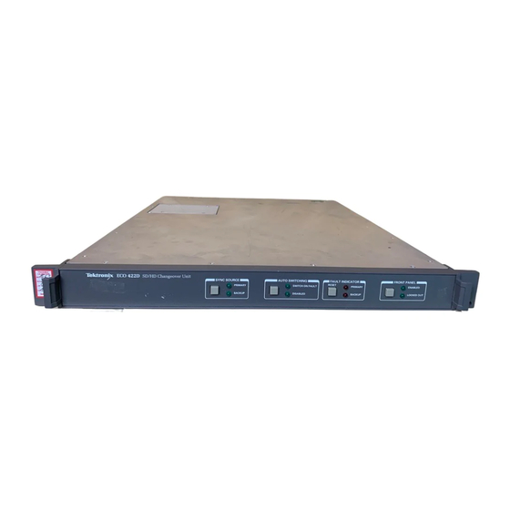
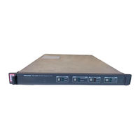
Tektronix ECO422D Manuals
Manuals and User Guides for Tektronix ECO422D. We have
5
Tektronix ECO422D manuals available for free PDF download: Instruction Manual, Technical Reference, Installation And Safety Instructions
Tektronix ECO422D Technical Reference (142 pages)
Video Sync Pulse Generator and ECO422D SD/HD changeover Unit System Integration
Brand:
Tektronix
| Category:
Control Unit
| Size: 6 MB
Table of Contents
Table of Contents
5
Important Safety Information
10
General Safety Summary
10
Service Safety Summary
12
Terms in this Manual
13
Symbols and Terms on the Product
13
Preface
15
Stay Genlock
15
Supported Products
15
Related Documentation
21
Table I: ECO422D SD/HD Changeover Unit Documentation
21
Table II: SPG600/300 Sync Pulse Generators Documentation
21
Table III: SPG8000 Master Sync / Clock Reference Generator Documentation
22
Table IV: TG700 TV Signal Generator Platform Documentation
23
Table V: TG8000 Multiformat Test Signal Generator Documentation
24
Physical, Power, and Environmental Specifications
25
ECO422D Specifications
25
Table 1: ECO422D Physical Specifications
25
Table 2: ECO422D Power Specifications
25
Table 3: ECO422D Environmental Specifications
26
SPG600/300 Specifications
27
Table 4: SPG600/300 Physical Specifications
27
Table 5: SPG600/300 Power Specifications
27
Figure 1: SPG600 Dimensions
28
Figure 2: SPG300 Dimensions
29
Table 6: SPG600/300 Environmental Specifications
30
SPG8000 Specifications
31
Table 7: SPG8000 Physical Specifications
31
Table 8: SPG8000 Power Specifications
31
Figure 3: SPG8000 Dimensions
32
Table 9: SPG8000 Environmental Specifications
33
TG700 and TG8000 Specifications
34
Table 10: TG700 and TG8000 Physical Specifications
34
Table 11: TG700 and TG8000 Power Specifications
34
Figure 4: TG700 Dimensions
35
Figure 5: TG8000 Dimensions
36
Table 12: TG700 and TG8000 Environmental Specifications
37
Installation
39
ECO422D Installation
39
Figure 6: ECO422D Front Rail Mount
39
Figure 7: ECO422D Deep Rackmount
40
Figure 8: ECO422D Shallow Rackmount
40
Figure 9: ECO422D Assembly of Rackmounting Hardware
41
Figure 10: ECO422D Installing or Removing the Rack Slides
42
Figure 11: ECO422D User Configuration Switches (Default Position)
43
Table 13: Switch Functions
44
Table 14: Factory Settings of Channel Configuration Switches (S1 - S11)
44
Table 15: Truth Table for ECO422D Switching
46
SPG600/300 Installation
50
Table 16: SPG600 Tools Required for Rackmount Installation
50
Figure 12: Assembly and Mounting of Rails
51
Figure 13: Installing or Removing the Instrument into or from the Rack
53
SPG8000 Installation
54
Figure 14: Installing or Removing the SPG8000 into or from the Rack
55
TG700 and TG8000 Installation
59
Figure 15: TG700 and TG8000 Slot Numbering (TG8000 Shown)
61
Figure 16: Removing the Blank Panel
62
Figure 17: Installing a Module
63
Figure 18: Securing the Module
63
Figure 19: Removing the Module
64
Figure 20: Mainframe Internal Frequency Calibration Menu
66
Figure 21: Mainframe Gain Calibration Menu (TG700 Only)
66
Instrument Connections
67
ECO422D Connections
67
Figure 22: ECO422D Rear Panel
67
Table 17: ECO422D Input Ratings
67
Figure 23: ECO422D Remote Connector Pins
68
Table 18: ECO422D Remote Connector Pinout
68
Figure 24: ECO422D Wiring Required to Conform with SMPTE Fault Reporting
69
SPG600/300 Connections
70
Figure 25: SPG600 Rear Panel (with Options 02 and 03)
70
Figure 26: SPG300 Rear Panel (with Option 02)
70
SPG8000 Connections
73
Figure 27: SPG8000 Rear Panel
73
Table 19: GPI Port - Connector Pin Assignments
76
Table 20: GPI/LTC Port - Connector Pin Assignments
78
TG700 and TG8000 Connections
79
Figure 28: TG700 Rear Panel
79
Figure 29: TG8000 Rear Panel
79
Table 21: Pin Assignments of the Mainframe GPI Connector
80
Figure 30: AG7 Module Connectors
81
Figure 31: Location of J452 on the AG7 Module
81
Figure 32: AGL7 Module Connectors
82
Figure 33: Location of J040 and J960 on the AGL7 Module
83
Figure 34: ATG7 Module Connectors
84
Figure 35: AVG7 Module Connectors
84
Figure 36: AWVG7 Module Connectors
85
Figure 37: BG7 Module Connectors
85
Figure 38: DVG7 Module Connectors (Option BK)
86
Figure 39: GPS7 Module Connectors
87
Table 22: GPS7 Module LTC/GPI Connector Pin Assignments
88
Figure 40: Simplified GPS Antenna System
89
Figure 41: HD3G7 Module Connectors
91
Figure 42: HDLG7 Module Connectors
92
Figure 43: HDVG7 Module Connectors (Option BK)
93
Figure 44: SDI7 Module Connectors
94
Video System Installation
97
SPG300 SD System Installation
97
Table 23: Connections for an SD System Using Two Spg300'S and an ECO422D
98
SPG600 SD System Installation
99
Table 24: Connections for an SD System Using Two Spg600'S and an ECO422D
100
SPG8000 SD/HD/3G with Option GPS System Installation
101
Figure 47: Connections for an SD/HD/3G System with GPS Using Two Spg8000'S and an ECO422D
102
Table 25: Connections for a System Using Two Spg8000'S with Option GPS and an ECO422D
103
SPG8000 SD/HD/3G Without Option GPS System Installation
104
Figure 48: Connections for a System Using Two Spg8000'S Without GPS and an ECO422D
105
Table 26: Connections for a System Using Two Spg8000'S Without GPS and an ECO422D
106
TG700 and TG8000 SD/HD System Installation
107
And an ECO422D
108
Table 27: Connections for an SD/HD System Using Two Tg700'S or Tg8000'S and an ECO422D
109
TG700 or TG8000 SD/HD/3G with GPS System Installation
110
HDVG7 Modules) and an ECO422D
111
Table 28: Connections for an SD/HD System with GPS Using Two Tg700'S or Tg8000'S
112
HDVG7 Module and DVG7 Module) and an ECO422D
114
Table 29: Connections for an SD/HD System with GPS Using Two Tg700'S or Tg8000'S (HDVG7 Module and DVG7 Module) and an ECO422D
115
SDI7 Modules) and an ECO422D
117
Table 30: Connections for an SD/HD System with GPS Using Two Tg700'S or Tg8000'S (Two SDI7 Modules) and an ECO422D
118
Power on / Power off Procedures
119
ECO422D Power on / Power off
119
SPG8000/600/300 and TG700/TG8000 Power on / Power off
120
Network Operation
121
ECO422D Networking
121
SPG600/300 Networking
121
SPG8000 Networking
121
TG700 and TG8000 Networking
123
Appendix A: Using Stay Genlock
127
Overview of Facility Timing
127
Figure 53: Dual Sync Pulse Generators with Emergency Changeover Unit
128
Figure 54: System Timing and Output Timing Adjustment
129
About Stay Genlock
130
Effect of Random Noise on HD-SDI Timing Jitter
132
Figure 57: Effect of Random Noise on the Genlock Input
133
Effect of Hum on HD-SDI Timing Jitter
134
Figure 58: Effect of Hum on the Genlock Input
135
Enabling Stay Genlock ® on the SPG600/300
136
Enabling Stay Genlock ® on the SPG8000
137
Enabling Stay Genlock ® on the TG700 and TG8000
138
Advertisement
Tektronix ECO422D Instruction Manual (167 pages)
SD/HD Changeover Unit Signal Generator
Brand:
Tektronix
| Category:
Portable Generator
| Size: 2 MB
Table of Contents
Table of Contents
7
General Safety Summary
11
Figure 1- 1: Front Panel of the ECO422D
19
Product Description 1
19
Figure 1- 2: Rear Panel of the ECO422D
19
Accessories 1
20
Figure 1- 3: Front Rail Mount
21
Figure 1- 4: Deep Rackmount
21
Getting Started
22
Figure 1- 7: Installing or Removing the Rack Slides
23
Table 1- 1: Power Cord Identification
25
Configuration 1
25
Figure 1- 8: Example of ECO422D Connections
26
Cable Installation
26
Figure 1- 9: Default Position of the User Configuration and Mode Switches
28
Table 1- 2: Default Configuration of Switches
29
Table 1- 3: Channel Configuration Switch Log (S1 - S11)
29
Figure 1- 10: Setup for the Functional Check
30
Functional Check and First Time Operation 1
30
Figure 2- 1: Front-Panel Controls
35
Controls and Indicators 2
35
Figure 2- 2: Default Position of the User Configuration and Mode Switches
36
Table 2- 1: Factory Settings of Channel Configuration Switches (S1 - S11)
37
Figure 2- 3: Rear Panel of the ECO422D
38
Connectors 2
38
Figure 2- 4: Remote Connector Pins
39
Fault Reporting
39
Table 2- 2: Remote Connector Pin-Out
39
Operating Basics 2
39
Figure 2- -5: Wiring Required to Conform with SMPTE
40
State Machine Description 2
41
Table 2- 3: Truth Table for ECO422D Switching
42
Figure 2- -6: Setup for Adjusting R265 (the User Level for
43
Exterior Cleaning 2
44
Introduction 3
47
Table 3- 1: General Characteristics
48
Figure 3- 1: Typical Eye-Pattern of 20 M of Belden 1694A Cable
49
Figure 3- 2: Typical Eye-Pattern of Channels 1- 6 HD Output
49
Table 3- 2: Signal Loss Detection
50
Table 3- 3: Power Supply
51
Table 3- 4: Mechanical (Physical) Characteristics
51
Table 3- 5: Environmental Characteristics
52
Table 3- 6: Certifications and Compliances
53
Figure 1- 5: Shallow Rackmount
22
Figure 1- 6: Assembly of Rackmounting Hardware
22
Specifications
61
Theory of Operation
61
Figure 4- 1: Block Diagram of the ECO422D
62
ECO422D Block Level Description 4
62
Figure 4- 2: Block Diagram of the Input Comparator
63
ECO422D Detailed Circuit Description 4
63
Figure 4- 3: Block Diagram for the Control and Remote Circuit
64
Control and Remote 4 of the A2 Main Board 4
64
Figure 4- 4: Reference Voltage and Selector Switch Farm Block Diagram
67
Reference Voltage and Selector Switch Farm 5 of the A2 Main Board 4
67
Calibration Data Report 5
71
Performance Verification
73
Equipment Required 5
77
Figure 5- 1: Setup to Check Black Burst Levels
78
Performance Verification Procedure 5
78
Figure 5- 2: Setup to Check the Component Serial Digital Video Levels
82
Figure 5- -3: Setup to Check the Serial Digital Video
85
Figure 5- 4: Setup to Check the Serial Audio Levels
87
Preparation 7
99
Table 7- 1: Static-Sensitive Components
101
Table 7- 2: Assemblies in the ECO422D
105
Removal/Replacement Instructions 7
107
Repackaging Instructions 7
109
Parts Ordering Information 8
113
Using the Replaceable Electrical Parts List 8
114
Replaceable Electrical Parts 8
115
Corrective Maintenance 7
102
Tektronix Service Offerings 7
104
Replaceable Electrical Parts
116
Appendix A: Options
166
Table A- 1: Power Cord Identification
167
Tektronix ECO422D Instruction Manual (128 pages)
SD/HD Changeover Unit
Brand:
Tektronix
| Category:
Switch
| Size: 1 MB
Table of Contents
Instruction Manual
1
Table of Contents
7
Environmental Considerations
15
Figure 1- 1: Front Panel of the ECO422D
21
Product Description 1
21
Accessories 1
22
Figure 1- 2: Rear Panel of the ECO422D
22
Installation 1
23
Figure 1- 3: Front Rail Mount
23
Figure 1- 4: Deep Rackmount
24
Figure 1- 5: Shallow Rackmount
24
Figure 1- 6: Assembly of Rackmounting Hardware
25
Figure 1- 7: Installing or Removing the Rack Slides
26
Configuration 1
28
Figure 1- 8: Example of ECO422D Connections
29
Table 1- 1: Default Configuration of Switches
31
Figure 1- 9: Default Position of the User Configuration and Mode Switches
31
Table 1- 2: Channel Configuration Switch Log (S1 - S11)
32
Functional Check and First Time Operation 1
33
Figure 1- 10: Setup for the Functional Check
33
Controls and Indicators 2
39
Figure 2- 1: Front-Panel Controls
39
Figure 2- 2: Default Position of the User Configuration and Mode Switches
40
Table 2- -1: Factory Settings of Channel Configuration
41
Connectors 2
42
Operating Basics 2
43
Fault Reporting
44
Figure 2- 4: Remote Connector Pins
44
Figure 2- 3: Rear Panel of the ECO422D
43
Table 2- 2: Remote Connector Pin-Out
44
Figure 2- -5: Wiring Required to Conform with SMPTE
45
State Machine Description 2
46
Table 2- 3: Truth Table for ECO422D Switching
47
Figure 2- -6: Setup for Adjusting R265 (the User Level for
48
Figure 2- 7: Selection Switches and User Level Control Locations
49
Exterior Cleaning 2
50
Introduction 3
53
Table 3- 1: General Characteristics
54
Figure 3- 1: Typical Eye-Pattern of 20 M of Belden 1694A Cable
55
Figure 3- 2: Typical Eye-Pattern of Channels 1- 6 HD Output
56
Table 3- 2: Signal Loss Detection
57
Table 3- 3: Power Supply
58
Table 3- 4: Mechanical (Physical) Characteristics
58
Table 3- 5: Environmental Characteristics
59
Table 3- 6: Certifications and Compliances
60
Theory of Operation
67
Logic Conventions
67
ECO422D Block Level Description 4
68
Figure 4- 1: ECO422D Block Diagram
68
ECO422D Option ELSW Block Level Description 4
69
Figure 4- 2: ECO422D Option ELSW Block Diagram
69
Calibration Data Report 5
73
Performance Verification
75
Equipment Required 5
79
Performance Verification Procedure 5
80
Figure 5- 1: Setup to Check Black Burst Levels
81
Figure 5- 2: Setup to Check the Component Serial Digital Video Levels
85
Figure 5- 3: Setup to Check the Serial Digital Video Composite Levels
87
Figure 5- 4: Setup to Check the Serial Audio Levels
90
Figure 5- 5: Setup to Check the Component Serial Digital Video Levels
92
Preparation 7
101
Table 7- 1: Static-Sensitive Components
103
Corrective Maintenance 7
104
Tektronix Service Offerings 7
106
Remove the Connector Board 7
108
Advertisement
Tektronix ECO422D Instruction Manual (122 pages)
SD/HD Changeover Unit Signal Generators S/N C050000 and above
Brand:
Tektronix
| Category:
Portable Generator
| Size: 2 MB
Table of Contents
Table of Contents
7
General Safety Summary
11
Table I: Product Documentation
16
Figure 1- 1: Front-Panel Controls
19
Controls and Indicators 1
19
Figure 1- 2: Default Position of the User Configuration and Mode Switches
20
Table 1- 1: Factory Settings of Channel Configuration Switches (S1 - S11)
21
Connectors 1
23
Fault Reporting
24
Figure 1- 4: Remote Connector Pins
24
Figure 1- 3: Rear Panel of the ECO422D
23
Operating Basics 1
24
Table 1- 2: Remote Connector Pin-Out
24
Figure 1- -5: Wiring Required to Conform with SMPTE
25
State Machine Description 1
26
Table 1- 3: Truth Table for ECO422D Switching
27
Figure 1- -6: Setup for Adjusting R265 (the User Level for
28
Figure 1- 7: Selection Switches and User Level Control Locations
29
Introduction 2
33
Specifications
34
Table 2- 1: General Characteristics
34
Figure 2- 1: Typical Eye-Pattern of 20 M of Belden 1694A Cable
36
Figure 2- 2: Typical Eye-Pattern of Channels 1- 6 HD Output
36
Table 2- 2: Signal Loss Detection
37
Table 2- 3: Power Supply
38
Table 2- 4: Mechanical (Physical) Characteristics
38
Table 2- 5: Environmental Characteristics
39
Logic Conventions 3
45
ECO422D Block Level Description 3
46
Figure 3- 1: ECO422D Block Diagram
46
ECO422D Option ELSW Block Level Description 3
47
Figure 3- 2: ECO422D Option ELSW Block Diagram
47
Calibration Data Report 4
51
Performance Verification
53
Equipment Required 4
57
Performance Verification Procedure 4
58
Figure 4- 1: Setup to Check Black Burst Levels
59
Figure 4- 4: Setup to Check the Serial Audio Levels
68
Adjustment Procedure
75
Service Options 6
79
Table 6- 1: Static-Sensitive Components
81
Corrective Maintenance 6
82
Tektronix Service Offerings 6
84
Removal/Replacement Procedures 6
86
Table 6- 2: Chassis Replacement Tools List
86
Table 6- 3: Tightening Specifications for Chassis Components
89
Repackaging Instructions
100
Replaceable Electrical Parts 7
101
Replaceable Electrical Parts
103
Tektronix ECO422D Installation And Safety Instructions (36 pages)
SD/HD Changeover Unit Signal Generators
Brand:
Tektronix
| Category:
Portable Generator
| Size: 0 MB
Table of Contents
Table of Contents
5
General Safety Summary
7
Preface
9
Product Description
9
Product Documentation
10
Compliance Information
11
EMC Compliance
11
Safety Compliance
12
Environmental Considerations
14
Operating Requirements
15
Electrical Ratings
15
Input Ratings
16
Environmental Ratings
16
Physical Specifications
17
Front-Panel Controls and Connectors
18
Rear-Panel Controls and Connectors
19
Installation
22
Mechanical Installation
22
Electrical Installation
26
User Switch Configuration
28
Power-On and Power-Off Procedure
33
Functional Check and First Time Operation
34
Advertisement
Related Products
Tektronix ECO 422
Tektronix ECO8000 Series
Tektronix ECO8020
Tektronix ECO170A
Tektronix ECO800UP
Tektronix ECO802UP
Tektronix 067-0885-00
Tektronix 067-1049-00
Tektronix 067-1056-00
Tektronix 070-8667-04
Tektronix Categories
Test Equipment
Measuring Instruments
Amplifier
Portable Generator
Printer
More Tektronix Manuals
Login
Sign In
OR
Sign in with Facebook
Sign in with Google
Upload manual
Upload from disk
Upload from URL