Tektronix ECO422D Technical Reference
Video sync pulse generator and eco422d sd/hd changeover unit system integration
Hide thumbs
Also See for ECO422D:
- Instruction manual (167 pages) ,
- Installation and safety instructions (36 pages) ,
- Instruction manual (122 pages)
Table of Contents
Advertisement
Quick Links
Download this manual
See also:
Instruction Manual
Advertisement
Table of Contents

Subscribe to Our Youtube Channel
Related Manuals for Tektronix ECO422D


Summary of Contents for Tektronix ECO422D
- Page 1 Video Sync Pulse Generator and ECO422D SD/HD Changeover Unit System Integration Technical Reference *P077056303* 077-0563-03...
- Page 3 Video Sync Pulse Generator and ECO422D SD/HD Changeover Unit System Integration Technical Reference www.tektronix.com 077-0563-03...
- Page 4 Copyright © Tektronix. All rights reserved. Licensed software products are owned by Tektronix or its subsidiaries or suppliers, and are protected by national copyright laws and international treaty provisions. Tektronix products are covered by U.S. and foreign patents, issued and pending. Information in this publication supersedes that in all previously published material.
-
Page 5: Table Of Contents
ECO422D power on / power off ................SPG8000/600/300 and TG700/TG8000 power on / power off .......... Network operation....................ECO422D networking..................SPG600/300 networking ..................SPG8000 networking..................TG700 and TG8000 networking ................Video Sync Pulse Generator and ECO422D SD/HD Changeover Unit System Integration... - Page 6 Effect of hum on HD-SDI timing jitter..............Enabling Stay GenLock on the SPG600/300 ............® Enabling Stay Genlock on the SPG8000 ............... ® Enabling Stay GenLock on the TG700 and TG8000 ..........® Index Video Sync Pulse Generator and ECO422D SD/HD Changeover Unit System Integration...
- Page 7 Figure 22: ECO422D rear panel ................. Figure 23: ECO422D remote connector pins..............Figure 24: ECO422D wiring required to conform with SMPTE fault reporting ......Figure 25: SPG600 rear panel (with options 02 and 03) ............Figure 26: SPG300 rear panel (with option 02)..............
- Page 8 Figure 46: Connections for an SD system using two SPG600’s and an ECO422D......Figure 47: Connections for an SD/HD/3G system with GPS using two SPG8000’s and an ECO422D. Figure 48: Connections for a system using two SPG8000’s without GPS and an ECO422D ....
- Page 9 Table 24: Connections for an SD system using two SPG600’s and an ECO422D ......Table 25: Connections for a system using two SPG8000’s with Option GPS and an ECO422D ..Table 26: Connections for a system using two SPG8000’s without GPS and an ECO422D....
-
Page 10: Important Safety Information
Read the safety sections of the other component manuals for warnings and cautions related to operating the system. When incorporating this equipment into a system, the safety of that system is the responsibility of the assembler of the system. Video Sync Pulse Generator and ECO422D SD/HD Changeover Unit System Integration... - Page 11 Do not operate in an explosive atmosphere. Keep product surfaces clean and dry. Remove the input signals before you clean the product. Video Sync Pulse Generator and ECO422D SD/HD Changeover Unit System Integration...
-
Page 12: Service Safety Summary
Disconnect power, remove battery (if applicable), and disconnect test leads before removing protective panels, soldering, or replacing components. Verify safety after repair. Always recheck ground continuity and mains dielectric strength after performing a repair. viii Video Sync Pulse Generator and ECO422D SD/HD Changeover Unit System Integration... -
Page 13: Terms In This Manual
find out the nature of the potential hazards and any actions which have to be taken to avoid them. (This symbol may also be used to refer the user to ratings in the manual.) The following symbol(s) may appear on the product: Video Sync Pulse Generator and ECO422D SD/HD Changeover Unit System Integration... - Page 14 Important safety information Video Sync Pulse Generator and ECO422D SD/HD Changeover Unit System Integration...
-
Page 15: Preface
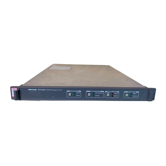
Supported products The information in this manual covers the Tektronix products described below. ECO422D SD/HD The ECO422D is a highly versatile sync changeover unit designed for use in a serial SD/HD digital television environment. The ECO422D will accommodate Changeover Unit component or composite serial digital video signals, AES/EBU digital audio, tri-level sync, and analog black-burst signals. - Page 16 However, in the unlikely event both sync sources are faulty, the ECO422D will not alternate between the two sources. If necessary, this function may be overridden with the manual sync source selection.
- Page 17 GPS signal is interrupted, and the Holdover Recovery mode will ensure a shock-free re-alignment of frequency and phase when the GPS signal is restored. Video Sync Pulse Generator and ECO422D SD/HD Changeover Unit System Integration xiii...
- Page 18 Time code is available as VITC on black outputs (GPS7, BG7), as Ancillary Time Code (ATC) (HDVG7, HD3G7), from four independent LTC outputs (GPS7), and as a response to time requests on a Simple Network Time Protocol (SNTP version 3.0) Server. Video Sync Pulse Generator and ECO422D SD/HD Changeover Unit System Integration...
- Page 19 Full frame test and custom patterns can be generated for the AVG7, AWVG7, DVG7, and HDVG7 modules. Simple full frame patterns are available on the software CD-ROM (version 3.1 or higher). Video Sync Pulse Generator and ECO422D SD/HD Changeover Unit System Integration...
- Page 20 The clock/frame trigger output can be used to trigger an oscilloscope to be synchronous with the video output. Video Sync Pulse Generator and ECO422D SD/HD Changeover Unit System Integration...
-
Page 21: Related Documentation
Describes how to service the instrument to the module level (such as circuit boards and fuses), lists the product specifications, and provides a procedure for verifying the performance of the instrument Video Sync Pulse Generator and ECO422D SD/HD Changeover Unit System Integration xvii... -
Page 22: Table Iii: Spg8000 Master Sync / Clock Reference Generator Documentation
(memory) devices in the product for customers with data security concerns. Release Notes 077-0751-xx Describes the new features, improvements, and limitations of the instrument firmware xviii Video Sync Pulse Generator and ECO422D SD/HD Changeover Unit System Integration... -
Page 23: Table Iv: Tg700 Tv Signal Generator Platform Documentation
(memory) devices in the product for customers with data security concerns. Release Notes 077-0228-xx (English) Describes the new features, improvements, and limitations of the instrument firmware 077-0443-xx (Japanese) Video Sync Pulse Generator and ECO422D SD/HD Changeover Unit System Integration... -
Page 24: Table V: Tg8000 Multiformat Test Signal Generator Documentation
Describes how to clear or sanitize the data Instructions storage (memory) devices in the product for customers with data security concerns. Release Notes 077-0689-xx Describes the new features, improvements, and limitations of the instrument firmware Video Sync Pulse Generator and ECO422D SD/HD Changeover Unit System Integration... -
Page 25: Physical, Power, And Environmental Specifications
Table 2: ECO422D power specifications Characteristic Description AC power source Voltage range 100 to 240 VAC Frequency range 50/60 Hz Power consumption 20 W typical Maximum power 40 W Video Sync Pulse Generator and ECO422D SD/HD Changeover Unit System Integration... -
Page 26: Table 3: Eco422D Environmental Specifications
. One hour per axis Second Manual Handling (Shock) Drop on all sides once from a height of 24 inches Drop on the bottom from a height of 48 inches Video Sync Pulse Generator and ECO422D SD/HD Changeover Unit System Integration... -
Page 27: Spg600/300 Specifications
AC power source Rating voltage 100 V to 240 V Frequency range 50/60 Hz Power consumption SPG600: 85 VA, 35 W SPG300: 65 VA, 30 W < 20 A Surge current Video Sync Pulse Generator and ECO422D SD/HD Changeover Unit System Integration... -
Page 28: Figure 1: Spg600 Dimensions
Physical, power, and environmental specifications Figure 1: SPG600 dimensions Video Sync Pulse Generator and ECO422D SD/HD Changeover Unit System Integration... -
Page 29: Figure 2: Spg300 Dimensions
Physical, power, and environmental specifications Figure 2: SPG300 dimensions Video Sync Pulse Generator and ECO422D SD/HD Changeover Unit System Integration... -
Page 30: Table 6: Spg600/300 Environmental Specifications
Nonoperating 22.3 m/s (2.28 G ), 5 Hz to 500 Hz, 10 minutes per axis, three axes Shock, Nonoperating 294 m/s (30 G), half-sine, 11 ms duration Video Sync Pulse Generator and ECO422D SD/HD Changeover Unit System Integration... -
Page 31: Spg8000 Specifications
50/60 Hz Power consumption 130 VA (maximum) on active power supply input 130 VA on backup supply input during 5 s daily load test Surge current < 40 A Video Sync Pulse Generator and ECO422D SD/HD Changeover Unit System Integration... -
Page 32: Figure 3: Spg8000 Dimensions
Physical, power, and environmental specifications Figure 3: SPG8000 dimensions Video Sync Pulse Generator and ECO422D SD/HD Changeover Unit System Integration... -
Page 33: Table 9: Spg8000 Environmental Specifications
, 5 Hz to 500 Hz, 10 minutes per axis, three axes Shock Operating Half-sine mechanical shocks, 30 g peak amplitude, 11 ms duration, 3 drops in each direction of each axis (18 total) Video Sync Pulse Generator and ECO422D SD/HD Changeover Unit System Integration... -
Page 34: Tg700 And Tg8000 Specifications
fluctuations do not exceed 10% of the operating voltage range. Frequency range TG700: 48 Hz to 63 Hz TG8000: 50/60 Hz Maximum power 120 VA Maximum current 1.2 A Video Sync Pulse Generator and ECO422D SD/HD Changeover Unit System Integration... -
Page 35: Figure 4: Tg700 Dimensions
Surge current ≤ 40 A peak for equal or less than 5 line cycles, after the instrument has been turned off for at least 30 seconds Figure 4: TG700 dimensions Video Sync Pulse Generator and ECO422D SD/HD Changeover Unit System Integration... -
Page 36: Figure 5: Tg8000 Dimensions
Physical, power, and environmental specifications Figure 5: TG8000 dimensions Video Sync Pulse Generator and ECO422D SD/HD Changeover Unit System Integration... -
Page 37: Table 12: Tg700 And Tg8000 Environmental Specifications
10 min, three axes Nonoperating (2.28 G ), 5 Hz to 500 Hz, 22.3 m/s 10 min, three axes Shock, Nonoperating 294 m/s (30 G), half-sine, 11 ms duration Video Sync Pulse Generator and ECO422D SD/HD Changeover Unit System Integration... - Page 38 Physical, power, and environmental specifications Video Sync Pulse Generator and ECO422D SD/HD Changeover Unit System Integration...
-
Page 39: Installation
17.75 inches to allow clearance for the slide-out tracks. Rack slides conveniently mount in any rack that has a front-to-rear rail spacing between 15.5 and 28 inches. The ECO422D requires six inches of clearance between the instrument rear panel and any rear cabinet panel for connector space and to provide adequate air circulation. -
Page 40: Figure 7: Eco422D Deep Rackmount
Installation Figure 7: ECO422D deep rackmount Figure 8: ECO422D shallow rackmount Video Sync Pulse Generator and ECO422D SD/HD Changeover Unit System Integration... -
Page 41: Figure 9: Eco422D Assembly Of Rackmounting Hardware
3. To completely remove the instrument from the rack, first be sure to disconnect all cabling. 4. Press both stop latches (visible in the stop-latch holes), and then carefully slide the instrument free from the rackmount tracks. Video Sync Pulse Generator and ECO422D SD/HD Changeover Unit System Integration... -
Page 42: Figure 10: Eco422D Installing Or Removing The Rack Slides
This does not apply to the three Option ELSW channels, which are buffered. To avoid this problem, work on an output only when the ECO422D is not in operation. Disconnect the output cable from the ECO422D before working on the cable, and verify proper termination before reconnecting the cable to the ECO422D. -
Page 43: Figure 11: Eco422D User Configuration Switches (Default Position)
CAUTION. Make sure that any channel that is not in use has checking disabled. If checking is not disabled, errors will always be generated and the ECO422D will not operate properly. No error checking also allows the maximum voltage, current, and frequency to pass through the ECO422D. -
Page 44: Table 13: Switch Functions
8 / S8 Serial Digital Video (Component) √ 9 / S9 Serial Digital Video (Component) √ 10 / S10 Serial Digital Audio √ 11 / S11 Serial Digital Audio Video Sync Pulse Generator and ECO422D SD/HD Changeover Unit System Integration... - Page 45 For Normal operation, the user cannot switch to a bad signal whether the instrument is in manual or auto switch mode. For example, the ECO422D is in manual mode and the Primary signal is bad, while the Backup signal is good. If the user presses the Sync Source button, the output will be the Backup signal.
-
Page 46: Table 15: Truth Table For Eco422D Switching
Installation State machine description The following is a truth table that gives the various states the ECO422D outputs based on the state of the inputs. Note that Primary is set to check a given level. Table 15: Truth table for ECO422D switching... - Page 47 Installation O Manual – Resulting output signal with the ECO422D set to “Manual” (no switching on error). It can either output Primary or Backup. 0 – Bad signal. 1 – Good signal. ↑ – Switch (change the current output signal).
- Page 48 10. Set the step attenuator to 3 dB of attenuation (or whatever attenuation is required for your application). 11. Check to see that the sync source has not changed to Backup and no faults are on the Primary channel. Video Sync Pulse Generator and ECO422D SD/HD Changeover Unit System Integration...
- Page 49 Installation 12. Slowly adjust R265 until the ECO422D switches to the Backup sync source and a fault occurs on the Primary channel. Press the Reset button to verify that the fault is still preset. If the Primary fault indicator LED goes out, continue adjusting the potentiometer.
-
Page 50: Spg600/300 Installation
Verify that the rack does not become unstable with the instrument fully extended. Do not leave the instrument extended when finished accessing the rear panel. Video Sync Pulse Generator and ECO422D SD/HD Changeover Unit System Integration... -
Page 51: Figure 12: Assembly And Mounting Of Rails
4. Repeat steps 2 and 3 to assemble the left rail assembly. Figure 12: Assembly and mounting of rails Video Sync Pulse Generator and ECO422D SD/HD Changeover Unit System Integration... - Page 52 4. When adjusting is completed, tighten all rail assembly 10-32 screws using 28 inch-lbs of torque. 5. If the instrument has knob screws on the front corners, tighten them so that they are secured in the rack. Video Sync Pulse Generator and ECO422D SD/HD Changeover Unit System Integration...
-
Page 53: Figure 13: Installing Or Removing The Instrument Into Or From The Rack
3. Tilt both lever handles upward simultaneously to allow them to clear the stops. (See Figure 13.) 4. Pull the instrument past the stops and out of the rack. Video Sync Pulse Generator and ECO422D SD/HD Changeover Unit System Integration... -
Page 54: Spg8000 Installation
3. Retighten any loose screws and push the instrument all the way into the rack. If the tracks do not slide smoothly, readjust the rail assemblies. 4. When adjusting is completed, tighten all rail assembly 10-32 screws using 28 inch-lbs of torque. Video Sync Pulse Generator and ECO422D SD/HD Changeover Unit System Integration... -
Page 55: Figure 14: Installing Or Removing The Spg8000 Into Or From The Rack
6. To remove the instrument from the rack, loosen the knob screws. Figure 14: Installing or removing the SPG8000 into or from the rack Video Sync Pulse Generator and ECO422D SD/HD Changeover Unit System Integration... - Page 56 See the SPG8000 Technical Reference manual for instructions on how to calibrate the oven oscillator when a GPS signal is not available. NOTE. Perform the internal oscillator frequency calibration at least once a year to compensate for oscillator drift. Video Sync Pulse Generator and ECO422D SD/HD Changeover Unit System Integration...
- Page 57 If the value is less than ±0.10e–6, then no calibration is required. Press the BACK button to exit the DIAGNOSTICS menu. Video Sync Pulse Generator and ECO422D SD/HD Changeover Unit System Integration...
- Page 58 The instrument will display the stored calibration value. 13. Press the ENTER button. 14. Press the BACK button to exit the calibration menu when the calibration is complete. Video Sync Pulse Generator and ECO422D SD/HD Changeover Unit System Integration...
-
Page 59: Tg700 And Tg8000 Installation
Do not touch module components or connector pins. Do not use any devices capable of generating or holding a static charge in the work area where you remove, install, or handle modules. Video Sync Pulse Generator and ECO422D SD/HD Changeover Unit System Integration... - Page 60 The TG700 Power Supply module is user replaceable and must be installed only in the position shown in the following figure. The TG700 Power Supply module cannot be installed in a TG8000 mainframe. Video Sync Pulse Generator and ECO422D SD/HD Changeover Unit System Integration...
-
Page 61: Figure 15: Tg700 And Tg8000 Slot Numbering (Tg8000 Shown)
figure. The TG8000 Power Supply module cannot be installed in a TG700 mainframe. Figure 15: TG700 and TG8000 slot numbering (TG8000 shown) Video Sync Pulse Generator and ECO422D SD/HD Changeover Unit System Integration... -
Page 62: Figure 16: Removing The Blank Panel
(See page 40, Removing a module.) Figure 16: Removing the blank panel CAUTION. Be careful not to damage the parts and cables inside of the module when you insert the module into the mainframe. Video Sync Pulse Generator and ECO422D SD/HD Changeover Unit System Integration... -
Page 63: Figure 17: Installing A Module
firmly engaged with the Main board of the mainframe. Figure 17: Installing a module 5. Tighten the two screws to secure the module to the mainframe. (See Figure 18.) Figure 18: Securing the module Video Sync Pulse Generator and ECO422D SD/HD Changeover Unit System Integration... -
Page 64: Figure 19: Removing The Module
4. Pull the module slowly toward you while supporting the terminations or BNC cables attached to the connectors. (See Figure 19.) Figure 19: Removing the module Video Sync Pulse Generator and ECO422D SD/HD Changeover Unit System Integration... - Page 65 GPS or a reference video signal. This stored frequency value is used when the instrument boots up and when there is a loss of signal lock and the instrument is configured to switch to internal timing. Video Sync Pulse Generator and ECO422D SD/HD Changeover Unit System Integration...
-
Page 66: Figure 20: Mainframe Internal Frequency Calibration Menu
To run the gain calibration, the instrument must be locked to a GPS reference. Figure 21: Mainframe gain calibration menu (TG700 only) Press the ENTER button to start the gain calibration routine or press the CANCEL button to exit the menu. Video Sync Pulse Generator and ECO422D SD/HD Changeover Unit System Integration... -
Page 67: Instrument Connections
WARNING. WARNING. To prevent personal injury, do not connect power to the ECO422D if the top cover is not installed. Dangerous potentials are present on the Power Supply board. Video Sync Pulse Generator and ECO422D SD/HD Changeover Unit System Integration... -
Page 68: Figure 23: Eco422D Remote Connector Pins
Toggle sync source (input) (Active low) Operates the same as the Sync Source button on the front panel. A low pulse will cause the ECO422D to toggle between Primary and Backup as the output signal. Indicate primary sync source active (Active high) Indicates that the Primary signals are the sync source. -
Page 69: Figure 24: Eco422D Wiring Required To Conform With Smpte Fault Reporting
Fault reporting + Normally open, indicates that everything is good. It will close in the cases of: loss of power to the ECO422D or one (or more) input signals have a fault. The fault Fault reporting – is latched and will remain until the fault is cleared. This fault reporting system... -
Page 70: Spg600/300 Connections
Instrument connections SPG600/300 connections Figure 25: SPG600 rear panel (with options 02 and 03) Figure 26: SPG300 rear panel (with option 02) Video Sync Pulse Generator and ECO422D SD/HD Changeover Unit System Integration... - Page 71 Serial digital black or serial digital test signal outputs. By default, the SDI 1 connector outputs a serial digital black signal, and the SDI 2 connector outputs a serial digital test signal. Use the System menu to change the output configuration. Video Sync Pulse Generator and ECO422D SD/HD Changeover Unit System Integration...
- Page 72 By default, these connectors output an AES/EBS serial digital audio. (XLR connector) Use the System menu to change the output configuration. WORD CLK 48 kHz word clock signal output. Video Sync Pulse Generator and ECO422D SD/HD Changeover Unit System Integration...
-
Page 73: Spg8000 Connections
Backup power supply The standard instrument includes one Power Supply module. With Option DPW, a second hot-swappable redundant (backup) Power Supply module is installed. (Option DPW only) Video Sync Pulse Generator and ECO422D SD/HD Changeover Unit System Integration... - Page 74 AES 5+6: Outputs channels 5 and 6 of the selected AES/EBU serial digital audio signal. AES 7+8: Outputs channels 7 and 8 of the selected AES/EBU serial digital audio signal. DARS: Outputs a DARS (muted audio) signal. Video Sync Pulse Generator and ECO422D SD/HD Changeover Unit System Integration...
- Page 75 Displays solid red if the connected antenna is shorted. A shorted antenna will not damage the GPS7 module. If a splitter is used on the antenna, it may Video Sync Pulse Generator and ECO422D SD/HD Changeover Unit System Integration...
-
Page 76: Table 19: Gpi Port - Connector Pin Assignments
GPI out 2 GPI input +5 V (1 k source resistance, so very limited current) GPI out 3 GPI preset select 3 GPI preset select 2 GPI preset select 1 Video Sync Pulse Generator and ECO422D SD/HD Changeover Unit System Integration... - Page 77 For correct operation if you use a VGA-to-BNC breakout cable, pins 6, 7, 8, and 10 must be internally grounded together in the cable and to the connector shell. Video Sync Pulse Generator and ECO422D SD/HD Changeover Unit System Integration...
-
Page 78: Table 20: Gpi/Ltc Port - Connector Pin Assignments
LTC 1 negative Ground +5 V (1 k source resistance, so very limited current) LTC 3 positive LTC 2 positive H BNC LTC 1 positive V BNC LTC 4 positive Video Sync Pulse Generator and ECO422D SD/HD Changeover Unit System Integration... -
Page 79: Tg700 And Tg8000 Connections
Dangerous potentials are present on the Power circuit board. The generator operates from an AC line frequency, over the range of 100 - 240 VAC (±10%), without the need for configuration. Video Sync Pulse Generator and ECO422D SD/HD Changeover Unit System Integration... -
Page 80: Table 21: Pin Assignments Of The Mainframe Gpi Connector
10 kΩ) Timing: Ignores pulses < 40 ms and always detects pulses > 60 ms Output Low < 0.4 V or ground (when sinking 100 ma; maximum on-resistance 4 Ω) Video Sync Pulse Generator and ECO422D SD/HD Changeover Unit System Integration... -
Page 81: Figure 30: Ag7 Module Connectors
CMOS compatible. Install the jumper on pins 1+2 of J452 to set the clock output level to 1V. Figure 31: Location of J452 on the AG7 module Video Sync Pulse Generator and ECO422D SD/HD Changeover Unit System Integration... -
Page 82: Figure 32: Agl7 Module Connectors
60 ms. The AGL7 module alarm output is available only when the mainframe GPI is enabled and the GPI ALARM OUTPUT menu item is set to Enable. Video Sync Pulse Generator and ECO422D SD/HD Changeover Unit System Integration... -
Page 83: Figure 33: Location Of J040 And J960 On The Agl7 Module
CW connector. NOTE. The word clock signal automatically follows the format of the Black 1 signal. Figure 33: Location of J040 and J960 on the AGL7 module Video Sync Pulse Generator and ECO422D SD/HD Changeover Unit System Integration... -
Page 84: Figure 34: Atg7 Module Connectors
CH 1: Outputs the selected analog component or composite video signal. CH 2: Outputs the selected analog component or composite video signal. CH 3: Outputs the selected analog component or composite video signal. Video Sync Pulse Generator and ECO422D SD/HD Changeover Unit System Integration... -
Page 85: Figure 36: Awvg7 Module Connectors
BLACK 4: Outputs the selected black burst or HDTV trilevel sync signal output. Option CB enables this connector to also output a 10 field ID or color bars signal. Video Sync Pulse Generator and ECO422D SD/HD Changeover Unit System Integration... -
Page 86: Figure 38: Dvg7 Module Connectors (Option Bk)
BLACK 2: Outputs the selected serial digital black signal (Option BK only). NOTE. The SIGNAL 1 and SIGNAL 2 connectors output the same test signal, and the BLACK 1 and BLACK 2 connectors output the same black signal. Video Sync Pulse Generator and ECO422D SD/HD Changeover Unit System Integration... -
Page 87: Figure 39: Gps7 Module Connectors
For correct operation if you use a VGA-to-BNC breakout cable, pins 6, 7, 8, and 10 must be internally grounded together in the cable and to the connector shell. Video Sync Pulse Generator and ECO422D SD/HD Changeover Unit System Integration... -
Page 88: Table 22: Gps7 Module Ltc/Gpi Connector Pin Assignments
NOTE. You can use the menus to independently set the format and timing of the three black outputs and to enable VITC to be applied to the output signal. Video Sync Pulse Generator and ECO422D SD/HD Changeover Unit System Integration... -
Page 89: Figure 40: Simplified Gps Antenna System
A simplified typical system is shown in the following figure to help you with planning and understanding the trade-offs of one set up versus another. (See Figure 40.) Figure 40: Simplified GPS antenna system Video Sync Pulse Generator and ECO422D SD/HD Changeover Unit System Integration... - Page 90 GPS7 end. For more complex systems, a variety of booster amplifiers, powered and passive splitters, DC blocks, and filters are available from a number of vendors. Video Sync Pulse Generator and ECO422D SD/HD Changeover Unit System Integration...
-
Page 91: Figure 41: Hd3G7 Module Connectors
field two. The frame pulse selection produces the once per field pulse for all other formats. NOTE. When the SECONDARY OUTPUT selection is set to Test Pattern the SIGNAL 1 and SIGNAL 2 connectors output the same test signal. Video Sync Pulse Generator and ECO422D SD/HD Changeover Unit System Integration... -
Page 92: Figure 42: Hdlg7 Module Connectors
HD SDI IN connector. LINK B: Outputs the selected HD-SDI dual-link video test signal or an upconverted version of the signal on the HD SDI IN connector. Video Sync Pulse Generator and ECO422D SD/HD Changeover Unit System Integration... -
Page 93: Figure 43: Hdvg7 Module Connectors (Option Bk)
SIGNAL 2: Outputs the selected serial digital video signal. BLACK 1: Outputs the selected serial digital black signal (Option BK only). BLACK 2: Outputs the selected serial digital black signal (Option BK only). Video Sync Pulse Generator and ECO422D SD/HD Changeover Unit System Integration... -
Page 94: Figure 44: Sdi7 Module Connectors
SIGNAL 2B: This output can be configured to output a test pattern, where it produces the same output as the Signal 2A output, or to output a Black signal in the same format as the Signal 2A output. Video Sync Pulse Generator and ECO422D SD/HD Changeover Unit System Integration... - Page 95 59.94, 29.97, and 23.98 fps) (Option 3G only) 148.5 MHz for signal formats such as 50p and 60p; 148.35 MHz for signal formats such as 59.94p. Video Sync Pulse Generator and ECO422D SD/HD Changeover Unit System Integration...
- Page 96 Instrument connections Video Sync Pulse Generator and ECO422D SD/HD Changeover Unit System Integration...
-
Page 97: Video System Installation
ELSW, channels 4-6 can accept only a black-burst or tri-level sync signal. Although the signal connections shown in this section support an ECO422D that has Option ELSW installed, the connections are valid for an ECO422D that does not have the option installed. -
Page 98: Table 23: Connections For An Sd System Using Two Spg300'S And An Eco422D
Video system installation Figure 45: Connections for an SD system using two SPG300’s and an ECO422D Table 23: Connections for an SD system using two SPG300’s and an ECO422D Connection number SPG300 SPG300 ECO422D (See Figure 45.) External signal primary connector... -
Page 99: Spg600 Sd System Installation
AES/EBU audio – Four BNC and two XLR outputs (can be set Analog audio) Word clock output Figure 46: Connections for an SD system using two SPG600’s and an ECO422D Video Sync Pulse Generator and ECO422D SD/HD Changeover Unit System Integration... -
Page 100: Table 24: Connections For An Sd System Using Two Spg600'S And An Eco422D
Video system installation Table 24: Connections for an SD system using two SPG600’s and an ECO422D Connection number SPG600 SPG600 ECO422D (See Figure 46.) External signal primary connector backup connector connector WORD CLK 1 PRIMARY WORD CLK 1 BACKUP SDI 2... -
Page 101: Spg8000 Sd/Hd/3G With Option Gps System Installation
SPG8000 SD/HD/3G with Option GPS system installation The following illustration shows how to connect two SPG8000's with Option GPS and an ECO422D for an SD/HD/3G video system. This system will occupy 2U in an equipment rack. Inputs. The following inputs are available. The example signal connections illustration uses a GPS signal reference input. -
Page 102: Figure 47: Connections For An Sd/Hd/3G System With Gps Using Two Spg8000'S And An Eco422D
Video system installation Figure 47: Connections for an SD/HD/3G system with GPS using two SPG8000’s and an ECO422D Video Sync Pulse Generator and ECO422D SD/HD Changeover Unit System Integration... -
Page 103: Table 25: Connections For A System Using Two Spg8000'S With Option Gps And An Eco422D
Video system installation Table 25: Connections for a system using two SPG8000’s with Option GPS and an ECO422D Connection number SPG8000 SPG8000 ECO422D (See Figure 48.) External signal primary connector backup connector connector SDI 2A 1 PRIMARY SDI 1A 2 PRIMARY... -
Page 104: Spg8000 Sd/Hd/3G Without Option Gps System Installation
SPG8000 SD/HD/3G without Option GPS system installation The following illustration shows how to connect two SPG8000’s without Option GPS and an ECO422D for an SD/HD/3G video system. This system will occupy 2U in an equipment rack. Inputs. The following inputs are available. The example signal connections illustration uses a Master Clock reference input. -
Page 105: Figure 48: Connections For A System Using Two Spg8000'S Without Gps And An Eco422D
Video system installation Figure 48: Connections for a system using two SPG8000’s without GPS and an ECO422D Video Sync Pulse Generator and ECO422D SD/HD Changeover Unit System Integration... -
Page 106: Table 26: Connections For A System Using Two Spg8000'S Without Gps And An Eco422D
Video system installation Table 26: Connections for a system using two SPG8000’s without GPS and an ECO422D Connection number SPG8000 SPG8000 ECO422D (See Figure 48.) External signal primary connector backup connector connector SDI 2A 1 PRIMARY SDI 1A 2 PRIMARY... -
Page 107: Tg700 And Tg8000 Sd/Hd System Installation
TG700 and TG8000 SD/HD system installation The following illustration shows how to connect two TG700’s or two TG8000’s and an ECO422D for an SD/HD video system. For this system, the TG700 or TG8000 has the following modules installed: AG7, AGL7, DVG7, and HDVG7. -
Page 108: And An Eco422D
Video system installation Figure 49: Connections for an SD/HD system using two generators (TG700’s with SDI7 modules shown) and an ECO422D Video Sync Pulse Generator and ECO422D SD/HD Changeover Unit System Integration... -
Page 109: Table 27: Connections For An Sd/Hd System Using Two Tg700'S Or Tg8000'S And An Eco422D
Video system installation Table 27: Connections for an SD/HD system using two TG700’s or TG8000’s and an ECO422D Connection number TG700 or TG8000 TG700 or TG8000 ECO422D (See Figure 49.) External signal primary connector backup connector connector HDVG7 – BLACK 1 1 PRIMARY HDVG7 –... -
Page 110: Tg700 Or Tg8000 Sd/Hd/3G With Gps System Installation
Up to seven channels of Black video outputs Up to four HD-SDI video outputs (two standard, two additional with option BK) AES/EBU audio – Five BNC outputs Word clock output Video Sync Pulse Generator and ECO422D SD/HD Changeover Unit System Integration... -
Page 111: Hdvg7 Modules) And An Eco422D
Video system installation Figure 50: Connections for an SD/HD system with GPS using two generators (TG700’s shown with HDVG7 modules) and an ECO422D Video Sync Pulse Generator and ECO422D SD/HD Changeover Unit System Integration... -
Page 112: Table 28: Connections For An Sd/Hd System With Gps Using Two Tg700'S Or Tg8000'S
BG7 – BLACK 1 10 PRIMARY BG7 – BLACK 1 10 BACKUP BG7 – BLACK 2 11 PRIMARY BG7 – BLACK 2 11 BACKUP GPS antenna GPS7 – Antenna GPS7 – Antenna Video Sync Pulse Generator and ECO422D SD/HD Changeover Unit System Integration... - Page 113 Up to four SD-SDI video outputs (two standard, two additional with option BK) Up to four HD-SDI video outputs (two standard, two additional with option BK) AES/EBU audio – Five BNC outputs Word clock output Video Sync Pulse Generator and ECO422D SD/HD Changeover Unit System Integration...
-
Page 114: Hdvg7 Module And Dvg7 Module) And An Eco422D
Video system installation Figure 51: Connections for an SD/HD system with GPS using two generators (TG700’s shown with HDVG7 module and DVG7 module) and an ECO422D Video Sync Pulse Generator and ECO422D SD/HD Changeover Unit System Integration... -
Page 115: Table 29: Connections For An Sd/Hd System With Gps Using Two Tg700'S Or Tg8000'S (Hdvg7 Module And Dvg7 Module) And An Eco422D
BG7 – BLACK 1 10 PRIMARY BG7 – BLACK 1 10 BACKUP BG7 – BLACK 2 11 PRIMARY BG7 – BLACK 2 11 BACKUP GPS antenna GPS7 – Antenna GPS7 – Antenna Video Sync Pulse Generator and ECO422D SD/HD Changeover Unit System Integration... - Page 116 GPS7, and SDI7. This system will occupy 3U in an equipment rack. NOTE. The ECO422D is not compliant to the 3G-SDI video standard. Only SD or HD signals should be connected to the ECO422D. This installation example allows you to use the generator to output SD/HD/3G SDI signals from the second channel of the SDI7 modules without redundancy.
-
Page 117: Sdi7 Modules) And An Eco422D
Video system installation Figure 52: Connections for an SD/HD system with GPS using two generators (TG700’s shown with SDI7 modules) and an ECO422D Video Sync Pulse Generator and ECO422D SD/HD Changeover Unit System Integration... -
Page 118: Table 30: Connections For An Sd/Hd System With Gps Using Two Tg700'S Or Tg8000'S (Two Sdi7 Modules) And An Eco422D
BG7 – BLACK 1 10 PRIMARY BG7 – BLACK 1 10 BACKUP BG7 – BLACK 2 11 PRIMARY BG7 – BLACK 2 11 BACKUP GPS antenna GPS7 – Antenna GPS7 – Antenna Video Sync Pulse Generator and ECO422D SD/HD Changeover Unit System Integration... -
Page 119: Power On / Power Off Procedures
3. When power is first applied, the front panel AUTO SWITCHING DISABLED LED will flash during the power-on delay. 4. When the ECO422D has completed the power-on delay, the SWITCH ON FAULT LED should come on. The length of the power-on delay is user adjustable. Use S13 to adjust the delay in approximately 30 second increments, from zero delay to approximately eight minutes. -
Page 120: Spg8000/600/300 And Tg700/Tg8000 Power On / Power Off
3. After connecting the power, make sure that the fan on the rear panel is working. If the fan is not working, turn off the power by disconnecting the power cable from the AC power source, and then contact your local Tektronix Field Office or representative. -
Page 121: Network Operation
Ethernet cable to connect between the Ethernet port on the SPG8000 and the Ethernet hub port of your local network. By connecting to an Ethernet network, you can access the SPG8000 using any PC on the network. Video Sync Pulse Generator and ECO422D SD/HD Changeover Unit System Integration... - Page 122 SYSTEM : NET SETUP : DHCP. 4. Press the left (◄) or right (►) arrow button to select Disable, and then press the ENTER button. Video Sync Pulse Generator and ECO422D SD/HD Changeover Unit System Integration...
-
Page 123: Tg700 And Tg8000 Networking
Refer to the PC Tools Technical Reference for detailed information about how to upload and download files using the Ethernet port. Video Sync Pulse Generator and ECO422D SD/HD Changeover Unit System Integration... - Page 124 Refer to your network administrator or to the user documentation supplied with your network server operating system (OS) for detailed information about DHCP server functions. Video Sync Pulse Generator and ECO422D SD/HD Changeover Unit System Integration...
- Page 125 NETWORK PARAMETERS submenu if you connect the generator to your local Ethernet network. 3. Verify the Ethernet connection by using a ping command from the PC. Video Sync Pulse Generator and ECO422D SD/HD Changeover Unit System Integration...
- Page 126 Network operation Video Sync Pulse Generator and ECO422D SD/HD Changeover Unit System Integration...
-
Page 127: Appendix A: Using Stay Genlock
® Digital video systems require synchronization and test signal sources with low jitter and high stability. The AGL7 and GPS7 modules of the Tektronix TG700 and TG8000 generators, the SPG600/300 Sync Pulse Generators and the SPG8000 Master Sync / Master Clock Reference Generators include the Stay GenLock technology, which provides a robust reference signal solution for broadcast and post-production facilities. -
Page 128: Figure 53: Dual Sync Pulse Generators With Emergency Changeover Unit
Appendix A: Using Stay GenLock ® Figure 53: Dual sync pulse generators with emergency changeover unit Video Sync Pulse Generator and ECO422D SD/HD Changeover Unit System Integration... -
Page 129: Figure 54: System Timing And Output Timing Adjustment
Individual SPG outputs can also be adjusted relative to the SPG clock for additional control. (See Figure 54.) Figure 54: System timing and output timing adjustment Video Sync Pulse Generator and ECO422D SD/HD Changeover Unit System Integration... -
Page 130: About Stay Genlock
® About Stay GenLock ® Stay GenLock is a digital genlock technology developed by Tektronix for the TG700 and TG8000 generators, SPG600/300 Sync Pulse Generators and the SPG8000 Master Sync / Master Clock Reference Generator. It provides additional robustness and stability for genlocked SPGs, as in a master/slave configuration. - Page 131 SPG without any disturbance to the sync and reference signals. Figure 56: Stable color burst with Stay Genlock (left) and rotating color burst without Stay Genlock (right) Video Sync Pulse Generator and ECO422D SD/HD Changeover Unit System Integration...
-
Page 132: Effect Of Random Noise On Hd-Sdi Timing Jitter
At –30 dB, the black burst input is unacceptable as a genlock reference. Using Stay Genlock, the timing jitter of the HD-SDI signal shows a very small increase as the noise level of the genlock reference signal increases beyond acceptable limits. Video Sync Pulse Generator and ECO422D SD/HD Changeover Unit System Integration... -
Page 133: Figure 57: Effect Of Random Noise On The Genlock Input
Appendix A: Using Stay GenLock ® Figure 57: Effect of random noise on the genlock input Video Sync Pulse Generator and ECO422D SD/HD Changeover Unit System Integration... -
Page 134: Effect Of Hum On Hd-Sdi Timing Jitter
HD-SDI output signal. Stay Genlock effectively rejects effects of big hum as demonstrated at the 0 dB hum level. (See Figure 58.) Video Sync Pulse Generator and ECO422D SD/HD Changeover Unit System Integration... -
Page 135: Figure 58: Effect Of Hum On The Genlock Input
Appendix A: Using Stay GenLock ® Figure 58: Effect of hum on the genlock input Video Sync Pulse Generator and ECO422D SD/HD Changeover Unit System Integration... -
Page 136: Enabling Stay Genlock ® On The Spg600/300
3. In the SPG Setup window, click the Genlock tab. 4. In the Lock Loss Action section, click Stay Current Frequency. 5. Click Apply to enable the setting change. 6. Close the SPG Setup window. Video Sync Pulse Generator and ECO422D SD/HD Changeover Unit System Integration... -
Page 137: Enabling Stay Genlock ® On The Spg8000
“shock” to the system. Fast Slew: Adjusts the instrument timing to match the recovered GPS signal at a rate 25 times faster than the legal rate without jumping. Video Sync Pulse Generator and ECO422D SD/HD Changeover Unit System Integration... -
Page 138: Enabling Stay Genlock ® On The Tg700 And Tg8000
1. Press the front-panel MODULE button until the GPS7 main menu appears. 2. Use the up (▲) or down (▼) arrow button to display REFERENCE, and then press the ENTER button to enter the Reference submenu. Video Sync Pulse Generator and ECO422D SD/HD Changeover Unit System Integration... - Page 139 “shock” to the system. Fast Slew: Adjusts the module timing to match the recovered GPS signal at a rate 25 times faster than the legal rate without jumping. Video Sync Pulse Generator and ECO422D SD/HD Changeover Unit System Integration...
- Page 140 Appendix A: Using Stay GenLock ® Video Sync Pulse Generator and ECO422D SD/HD Changeover Unit System Integration...
- Page 141 Rear-panel connectors, 69 CH 1 connector, 60 Ethernet port, 52 SIGNAL 1 connector, 69 CH 2 connector, 60 SIGNAL 2 connector, 69 CH 3 connector, 60 Rear-panel connectors, 60 Video Sync Pulse Generator and ECO422D SD/HD Changeover Unit System Integration...
- Page 142 SIGNAL 1A connector, 70 NETWORK SETUP SIGNAL 1B connector, 70 submenu, 100 SIGNAL 2A connector, 70 SIGNAL 2B connector, 70 TRIG OUT connector, 71 Setting Ethernet parameters, 100 Oven calibration, 32, 41 Video Sync Pulse Generator and ECO422D SD/HD Changeover Unit System Integration...
Need help?
Do you have a question about the ECO422D and is the answer not in the manual?
Questions and answers