Sign In
Upload
Manuals
Brands
Suzuki Manuals
Motorcycle
Intruder VS1400
Suzuki Intruder VS1400 Manuals
Manuals and User Guides for Suzuki Intruder VS1400. We have
3
Suzuki Intruder VS1400 manuals available for free PDF download: Service Manual, Owner's Manual
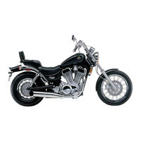
Suzuki Intruder VS1400 Service Manual (292 pages)
Brand:
Suzuki
| Category:
Motorcycle
| Size: 19 MB
Table of Contents
View of Suzuki VS1400GLF
3
Group Index
4
General Information
5
Serial Number Locations
6
Furl and Oil Recommendations
6
Final Gear Oil/Front Fork Oil
7
Brake and Clutch Fluid
7
Breaking-In Procedures
7
Cylinder Identification
7
Special Materials
8
Precautions and General Instructions
10
Use of Genuine Suzuki Parts
10
Specifications
11
Periodic Maintenance and Tune-Up Procedures
12
Periodic Maintenance Schedule
13
Battery Maintenance
14
Air Cleaner Maintenance
15
Spark Plug Maintenance
16
Engine Oil Change and Oil Filter Maintenance
18
Carburetor Maintenance
19
Necessary Amount of Engine Oil
19
Automatic De-Compression Cable Maintenance
20
Fuel Line Maintenance
21
Clutch Maintenance
21
Clutch Fluid Level
21
Bleeding Air from the Clutch Fluid Circuit
21
Final Gear Oil
22
Brake Maintenance
23
Brake Fluid Level
23
Bleeding Air from the Brake Fluid Circuit
24
Tire Tread Condition
25
Tire Pressure
26
Steering Maintenance
26
Front Fork Maintenance
26
Chassis Bolts and Nuts
27
Periodic Maintenance and Tune-Up Procedures - Illustrations
28
Lubrication Points
29
Engine
30
Compression Check
31
Engine Components Removable with the Engine in Place
32
Engine Removal
33
Engine Reinstallation
40
Engine Disassembly
42
Bearings and Oil Seals (Except for Crankshaft)
56
Engine Components Inspection and Servicing
57
Cylinder Head Disassembly and Servicing
57
Cylinder Head Cover Distortion
60
Rocker Arm Shaft O.D.
60
Rocker Arm I.D.
60
Cylinder Head Distortion
60
Valve Face Wear/Stem Runout
61
Valve Head Radial Runout
61
Valve Guide - Valve Stem Clearance
62
Valve Stem Wear
62
Valve Guide Servicing
62
Valve Stem Width
64
Valve Seat Servicing
64
Valve Stem End Condition
66
Valve Springs (Refer to Service Data)
66
Lash Adjuster Inspection
67
Cam Chain Tensioner
69
Cam Chain 20-Pitch Length
69
Camshaft
69
Cam Height
70
Camshaft Runout
70
Camshaft Journal Wear
70
Cylinder Distortion
71
Cylinder Bore
72
Piston Diameter
72
Piston-Cylinder Clearance
72
Piston Ring-Groove Clearance
73
Piston Ring - Free End Gap and End Gap
73
Oversize Piston Rings/Oil Rings/Side Rail
74
Piston Pin and Pin Bore
74
Conrod Small End Bore I.D.
75
Conrod Big End Thrust Clearance
75
Conrod-Crank Pin Bearing Selection
76
Conrod I.D. Specification
77
Crank Pin O.D. Specification
77
Bearing Thickness Table
78
Bearing Assembly
78
Crankshaft
79
Crankcase-Crankshaft Bearing - Oil Clearance
79
Crankshaft Thrust Clearance
80
List of Thrust Shims
81
Clutch
81
Clutch Dirve Plates and Driven Plates
81
Clutch Spring Free Lendth
82
Clutch Bearings/Cylinder
82
Clutch Cylinder Reassembly
83
Generator and Signal Generator
83
Starter Clutch
84
Transmission, Transmission Gears and Related Parts
87
Gear-Shifting Fork Clearance
88
Countershaft Reassembly
88
Driveshaft Reassembly
89
Engine Reassembly
90
Camshaft Timing
106
No 1 (Rear) Cylinder
107
No 2 (Front) Cylinder
108
Cam Shaft Timing
109
Cylinder Head Bolt/Cylinder Head Cover Bolt Diagrams
112
Gasket Position Diagram
113
Liquid Gasket Applying Places of Cylinder Head Cover
113
Shaft Drive
114
Shaft Drive Diagram
115
Secondary Bevel Gears Construction - Exploded Diagram
116
Secondary Drive Bevel Gear Removal and Disassembly
117
Secondary Driven Bevel Gear
118
Secondary Driven Bevel Gear Inspection
119
Damper Spring Check
119
Secondary Bevel Gears Reassembly
119
Secondary Drive Bevel Gear
119
Secondary Gears Shim Adjustment - Backlash
121
Tooth Contact
123
Final Assembly and Remounting
124
Secondary Bevel Gears Reassembly Information
125
Final Bevel Gears Construction
126
Final Gear Case Breather Circuit
127
Air and Gear Oil Flow in Final Gear Case Breather Circuit
127
Breather Circuit
127
Air/Oil Passage
127
Final Bevel Gears Removal and Disassembly
128
Final Gear Case
128
Propeller Shaft
128
Final Drive Bevel Gear
129
Driven Bevel Gear
130
Final Bevel Gears Inspection/Reassembly
133
Drive Bevel Gear
134
Final Gear Case and Bearing Case
135
Final Gear Shim Adjustment
138
Final Gear Bearing Case Shim Clearance
138
Final Bevel Gears Assembly and Remounting
141
Final Bevel Gears Reassembly Information
144
Fuel and Lubrication System
145
Fuel System Description and Diagram
146
Fuel System When Starting Engine/After Starting Engine
147
Fuel Cock
147
Main Cock
147
Sub Cock
148
Fuel Pump
148
Fuel Pump Relay
149
Carburetor Construction
150
No 1 (Rear) Carburetor
151
Carburetor Specifications
152
Diaphragm and Piston Operation
153
Slow System
154
Transient Enrichment System
154
Main System
155
Starter System
156
Float System
156
Carburetor Disassembly
157
Front Carburetor Disassembly
158
Rear Carburetor Disassembly
159
Carburetor Inspection
164
Carburetor Reassembly
165
Balancing Carburetors
166
Lubricatin System and Cooling System
169
Oil Pressure
169
Lubrication System Chart
171
Lubrication System Diagram
172
Cooling System Chart
173
Cooling System Diagram
174
Electrical System
175
Charging System Description
176
Function of Regulator
176
Charging System Inspection
178
Charging Output Check
178
AC Generator No-Load Performance
178
AC Generator Continuity Check
179
Regulator/Rectifier
179
Ignition System Description
180
Ignition System Inspection
181
Ignition Coils/Pick up Coil Check
181
Ignitor Unit (Transistor Unit) Check
182
Side Stand and Neutral Relay Check
184
Diode Check
184
Automatic De-Compression Control and Starter System Description/Operation
185
Starter Motor Removal/Disassembly/Inspection
186
Commutator Check
186
Bearings Check
186
Armature Coil Check
187
Starter Motor Reassembly
187
Housing End (Inside)/Screw
188
Starter Relay Inspection
188
Decompression Solenoid Control Unit
189
Timer I/II Inspection
189
De-Comp. Solenoid Inspection/Removal
191
Speedometer and Instrument Panel Removal and Disassembly
192
Speedometer and Instrument Panel Inspection
194
Lamps Diagrams
196
Switches
197
Oil Pressure Switch
198
Battery Removal
198
Battery Remounting/Specifications/Initial Charging
199
Battery Servicing
201
Recharging Operation
201
Chassis
202
Front Wheel Diagram/Removal/Disassembly
203
Brake Disc
204
Wheel Bearings Inspection
204
Axle Shaft/Wheel Rim/Tire Inspection
205
Front Wheel Reassembly
206
Front Brake
208
Brake Pad Replacement
208
Caliper Removal and Disassembly
208
Caliper and Disc Inspection
210
Caliper Reassembly
211
Master Cylinder Removal and Disassembly
211
Master Cylinder Inspection
213
Master Cylinder Reassembly
214
Front Fork Removal
214
Front Fork Disassembly
215
Front Fork Inspection
218
Inner Tube and Outer Tube/Damper Rod Ring Inspection
218
Front Fork Reassembly
218
Oil Lock Piece Installation
219
Damper Rod Bolt
219
Outer Tube Metal, Oil Seal and Dust Seal
219
Fork Oil
219
Fork Spring
220
Inner Tube
220
Handlebar and Steering Stem Diagram/Disassembly
221
Handlebar and Steering Stem Inspection/Reassembly
224
Stem Unit
225
Handlebar Holder
225
Handlebars
226
Rear Brake
227
Brake Pad Repacement (Rear Brake)
228
Caliper Removal and Disassembly (Rear Brake)
228
Cylinder and Piston Inspection
230
Rubber Part Inspection
230
Caliper Reassembly (Rear Brake)
231
Master Cylinder Removal and Disassembly (Rear Brake)
233
Cylinder Inspection
234
Piston, Cup Set and Rubber Parts Inspection
235
Master Cylinder Reassembly and Remounting
235
Rear Wheel Diagram/Removal/Disassembly
236
Rear Wheel Disassembly
237
Rear Wheel Inspection/Reassembly
238
Rear Suspension and Swingarm Diagram/Removal
240
Bearing/Dust Seal/Rear Shock Absorber Inspection
242
Swingarm and Rear Shock Absorber Reassembly
243
Clutch Master Cylinder Diagram
244
Clutch Master Cylinder Removal and Disassembly
245
Master Cylinder Inspection (Rear Wheel)
246
Master Cylinder Reassembly (Rear Wheel)
247
Servicing Information
248
Troubleshooting
249
Engine - Troubleshooting
249
Shaft Drive - Troubleshooting
251
Carburetor - Troubleshooting
252
Electrical - Troubleshooting
253
Battery/Chassis - Troubleshooting
254
Brakes - Troubleshooting
255
Wiring Diagram (for West Germany)
256
Wiring Diagram (for UK and Belgium)
257
Wiring Diagram (the Others)
258
Harness Routing Diagram
259
Starter Motor Lead Diagram
260
Generator Stator Diagram
261
Fuel Hose Routing Diagram
262
Oil Hose Routing Diagram
263
Front Brake Hose Routing Diagram
264
Bear Brake Hose Routing Diagram
265
Cable Routing Diagram
266
Location of Clutch/Front Brake Master Cylinder
268
Special Tools
269
Engine - Tightening Torque
274
Secondary and Final/Chassis - Tightening Torque
276
Tightening Torque Chart for Other Bolts and Nuts
277
Valve + Guide Service Data
278
Camshaft + Cylinder Head Service Data
279
Cylinder + Piston + Piston Ring Service Data
279
Conrod + Crankshaft Service Data
280
Oil Pump/Clutch/Transmission Service Data
281
Shaft Drive/Carburetor Service Data
282
Electrical Service Data
283
Wattage Service Data
284
Brake + Wheel Service Data
284
Suspension/Ture Pressure/Fuel + Oil Service Data
285
Clutch Set Bolts, Spacers and Springs
287
Modification of Pull Back Handlebars
288
Modification of the Fuel Hoses and Their Routing
289
Fuel Hose Routing
290
Advertisement
Suzuki Intruder VS1400 Owner's Manual (163 pages)
Brand:
Suzuki
| Category:
Motorcycle
| Size: 4 MB
Table of Contents
Table of Contents
7
The Sport of Motorcycling
9
Fuel, Engine Oil and Coolant Recommendation
20
Controls, Equipment and Adjust- Ments
25
Controls, Equipment and Adjustments
25
Location of Parts
26
Key
29
Ignition Switch
30
Steering Lock
31
Instrument Panel
32
Left Handlebar
34
Right Handlebar
35
Fuel Tank Cap
38
Fuel Valve
39
Choke Lever
41
Gearshift Lever
42
Helmet Holder
43
Rear Brake Pedal
43
Side Stand
44
Rear Suspension
46
Break-In and Inspection before Riding
47
Riding Tips
53
Starting the Engine
54
Starting off and Shifting
55
Using the Transmission
57
Riding on Hills
58
Stopping and Parking
59
Carrying a Passenger
61
Accessory Use and Motorcycle Loading
63
Inspection and Maintenance
69
Maintenance Schedule
70
Notice
70
Tools
75
General Lubrication
76
Battery
77
Air Cleaner
80
Spark Plug
90
Engine Oil
92
Carburetor
99
Clutch
102
Final Gear Oil
104
Brakes
106
Tires
112
Spoke Nipple Tightness
115
Side Stand/Ignition Inter-Lock System
116
Front Wheel Removal
118
Rear Wheel Removal
120
Light Bulb Replacement
123
Fuses/Output Terminal
128
Troubleshooting
131
Storage Procedure and Appear- Ance Care
137
Storage Procedure and Appearance Care
137
Motorcycle
138
Fuel
139
Battery
140
Engine
140
External
141
Tires
141
Maintenance During Storage
142
Procedure for Returning to Service
142
Corrosion Prevention
143
Motorcycle Cleaning
145
Inspection after Cleaning
147
Consumer Information
149
Emission Control Warranty
150
Tampering with Noise Control System Prohibited
151
Serial Number Location
152
Reporting Safety Defects
153
Location of Labels
154
Specifications
156
Index
160
Suzuki Intruder VS1400 Owner's Manual (68 pages)
Brand:
Suzuki
| Category:
Motorcycle
| Size: 22 MB
Table of Contents
Break-In (Running-In) Information
2
Table of Contents
3
Consumer Information
4
Accessory Information and Precautions Safety Tips
5
Safe Riding Recommendation for Motorcycle Riders
6
Serial Number Location
7
Table of Contents
8
Controls
8
Location of Parts
9
Handlebar View
9
Vehicle Left Side View
9
Vehicle Right Side View
10
Key
10
Ignition Switch
10
Steering Lock
11
Instrument Panel
11
Left Handlebar
12
Right Handlebar
13
Fuel Tank Cap
14
Fuel Valve
15
Fuel Valve
16
Off Position
16
Choke Handle
16
Gearshift Level
17
Rear Brake Pedal
17
Helmet Holder
17
Side Stand
18
Rear Suspension Spring Adjustment
19
Suspension Adjustment
19
Fuel and Oil Recommendation
20
Fuel/Oil Recommendation
21
Engine Oil
21
Final Gear Oil
22
SAE Engine Oil Viscosity
22
Jaso T903
22
Energy Conserving
22
Break-In (Running-In) and Inspection before Riding
23
Avoid Constant Low Speed
24
Vary the Engine Speed
24
Breaking in the New Tires
24
Maximum Engine Speed Recommendation
24
Inspection before Riding
25
Allow Engine to Circulate before Riding
25
Observe Your First and most Critical Service
25
Riding Tips
26
Starting the Engine
27
Starting off
27
Using the Transmission
28
Riding on Hills
29
Stopping and Parking
29
Inspection and Maintenance
30
Maintenance Schedule
31
Maintenance Chart
32
Lubrication Points
33
Tool
33
Battery
34
Air Cleaner
36
Spark Plugs
40
Plug Replacement Guide
40
Engine Oil Info
41
Engine Oil and Filter Change
41
Engine Level Check
41
Idle Speed Adjustment
44
Carburetor
44
Clutch
45
Throttle Cable Adjustment
45
Final Gear Oil Change
46
Brakes
47
Brake Fluid
47
Brake Pads
48
Rear Brake Pedal Adjustment
49
Rear Brake Light Switch
49
Tires
50
Tire Pressure and Loading
50
Spoke Nipple Tightness
50
Tire Conditon and Type
51
Cold Tire Inflation Pressure
51
Side Standing/Ignition Interlock Switch
52
Front Wheel Removal
52
Rear Wheel Removal
54
Light Bulb Replacement
55
Headlight
55
Tail/Brake Light
56
License Plate Light
56
Turn Signal Light
57
Headlight Beam Adjustment
57
Output Terminal
58
Fuse List
58
Fuses/Output Terminal Fuses
58
Troubleshooting
59
Fuel Supply Check
60
Motorcycle Cleaning and Storage Procedure
61
Ignition System Check
61
Engine Stalling
61
Washing the Motorcycle
62
Waxing the Motorcycle
62
Inspection after Cleaning
62
Storage Procedure
63
Specifications
65
Index
67
Advertisement
Advertisement
Related Products
Suzuki VS750
Suzuki Intruder VS700
Suzuki Intruder VS800
Suzuki V Storm
Suzuki Vstrom
Suzuki Vstrom DL650 K4
Suzuki Vstrom DL650A K9
Suzuki Vstrom DL1000 K9
Suzuki Intruder VS600GL
Suzuki V-STROM 800
Suzuki Categories
Motorcycle
Automobile
Motorcycle Accessories
Outboard Motor
Offroad Vehicle
More Suzuki Manuals
Login
Sign In
OR
Sign in with Facebook
Sign in with Google
Upload manual
Upload from disk
Upload from URL