Sign In
Upload
Manuals
Brands
ST Manuals
Motherboard
STM32H5
User Manuals: ST STM32H5 Discovery Kit
Manuals and User Guides for ST STM32H5 Discovery Kit. We have
5
ST STM32H5 Discovery Kit manuals available for free PDF download: Application Note, User Manual, Getting Started
ST STM32H5 Application Note (56 pages)
Brand:
ST
| Category:
Microcontrollers
| Size: 3 MB
Table of Contents
General Information
2
Table 2. Glossary
2
Overview
5
Security Purpose
5
Figure 1. Corrupted Connected Device Threat
5
Table 3. Assets to be Protected
6
Attack Types
7
Introduction to Attack Types
7
Software Attacks
8
Table 4. Attacks Types and Costs
8
Hardware Attacks
9
Non-Invasive Attacks
10
Silicon Invasive Attacks
11
Iot System Attack Examples
12
Figure 2. Iot System
12
List of Attack Targets
13
Device Protections
16
Configuration Protection
16
Trustzone ® for Armv8-M Architecture
16
Dual-Core Architecture
17
Figure 3. Armv8-M Trustzone® Execution Modes
17
Figure 4. Simplified Diagram of Dual-Core System Architecture
17
Memory Protections
18
Figure 5. Memory Types
18
System Flash Memory
19
User Flash Memory
19
Embedded SRAM
19
External Flash Memories
20
STM32 Memory Protections
21
Software Isolation
21
Debug Port and Other Interface Protection
21
Boot Protection
22
System Monitoring
22
Secure Applications
23
Secure Firmware Install (SFI)
23
Root and Chain of Trust
23
Stmicroelectronics Proprietary SBSFU Solution
23
Secure Boot (SB)
23
Secure Firmware Update (SFU)
24
Figure 6. Secure Boot FSM
24
Configurations
25
Arm TF-M Solution
25
Figure 7. Secure Server/Device SFU Architecture
25
Product Certifications
26
Table 8. Basic Feature Differences of Trustzone-Based Secure Software
26
STM32 Security Features
27
Overview of Security Features
27
Static and Dynamic Protections
27
Security Features by STM32 Devices
27
Table 10. Security Features for STM32L0/1/4/4+, STM32WB, STM32WL Devices
28
Readout Protection (RDP)
29
Table 11. Security Features for STM32L5, STM32U5, STM32H503/5, Stm32H72X/73/74X/75, Stm32H7Ax/7Bx, STM32F7 Devices
29
Figure 8. Example of RDP Protections (STM32L4 Series)
30
Lifecycle Management-Product State
31
Table 12. RDP Protections
31
One-Time Programmable (OTP)
32
Trustzone
32
Core State
33
Secure Attribution Unit (SAU)
33
Figure 9. Trustzone® Implementation at System Level
33
Memory and Peripheral Protections
34
Flash Memory Write Protection (WRP)
34
Execute-Only Firmware (PCROP)
34
Secure Hide Protection (HDP)
35
Firewall
35
Figure 10. HDP Protected Firmware Access
35
Figure 11. Firewall FSM
36
Figure 12. Firewall Application Example
36
Memory Protection Unit (MPU)
37
Table 13. Attributes and Access Permission Managed by MPU
37
Customer Key Storage (CKS)
38
Table 14. Process Isolation
38
Figure 13. Dual-Core Architecture with CKS Service
38
Antitamper (Tamp)/Backup Registers (BKP)
39
Clock Security System (CSS)
39
Power Monitoring (PVD)
39
Memory Integrity Hardware Check
39
Independent Watchdog (IWDG)
40
Device ID
40
Cryptography
40
Hardware Accelerators
40
Cryptolib Software Library
40
On-The-Fly Decryption Engine (OTFDEC)
41
Figure 14. Typical OTFDEC Configuration
41
Guidelines
42
Table 15. Security Use Cases
42
Conclusion
44
Appendix A Cryptography - Main Concepts
45
Secret Key Algorithms
45
Figure 15. Symmetric Cryptography
45
Public Key Algorithms (PKA)
46
Figure 16. Signature
46
Figure 17. PKA Encryption
46
Hash Algorithms
47
MAC or Signature and Certificate
47
Figure 18. Message Hashing
47
Figure 19. MAC Generation with Secrete Key Algorithm
47
Figure 20. Signature Generation with Public Key Algorithm
48
Revision History
49
Table 1. Applicable Products
49
Table 16. Document Revision History
49
Table 5. Memory Types and Associated Protection
50
Table 6. Scope of STM32 Embedded Memory Protection Features
50
Table 7. Software Isolation Mechanism
50
Table 9. Security Features for STM32C0, STM32F0/1/2/3/4, STM32G0/4 Devices
50
Advertisement
ST STM32H5 User Manual (44 pages)
Nucleo-144 board (MB1404)
Brand:
ST
| Category:
Computer Hardware
| Size: 10 MB
Table of Contents
Figure 1. NUCLEO-H563ZI Top View
1
Figure 2. NUCLEO-H563ZI Bottom View
1
Features
2
Ordering Information
3
Products and Codification
3
Table 1. Ordering Information
3
Table 2. Codification Explanation
3
Development Environment
4
System Requirements
4
Development Toolchains
4
Demonstration Software
4
Conventions
5
Table 3. ON/OFF Convention
5
Quick Start
6
Getting Started
6
Table 4. Default Jumper Configuration
6
Hardware Layout and Configuration
7
Figure 3. Hardware Block Diagram
7
STM32H5 Nucleo-144 Board Layout
8
Figure 4. STM32H5 Nucleo-144 Board Top Layout
8
Figure 5. STM32H5 Nucleo-144 Board Bottom Layout
9
Mechanical Drawing
10
Figure 6. STM32H5 Nucleo-144 Board Mechanical Drawing (in Millimeters)
10
Embedded STLINK-V3EC
11
Table 5. JP1 Configuration
12
Table 6. MIPI20 Debug Connector (CN5) Pinout
12
Figure 7. Connecting an External Debug Tool to Program the On-Board STM32
12
Power Supply
14
Power Supply Input from STLINK-V3EC USB Connector: 5V_STLK (Default Configuration)
14
Figure 8. Power Supply Input from STLINK-V3EC USB Connector with PC (5 V, 500 Ma Maximum)
14
External Power Supply Input from VIN (7 to 12 V, 800 Ma Maximum)
15
External Power Supply Input 5V_EXT (5 V, 1.3 a Maximum)
15
Table 7. External Power Sources VIN (7 to 12 V)
15
Table 8. Power Supply Input from 5V_EXT (5 V, 1.3 A)
15
Figure 9. Power Supply Input from VIN (7 to 12 V, 800 Ma Maximum)
15
External Power Supply Input from a USB Charger (5 V)
16
Table 9. External Power Source CHGR (5 V)
16
Figure 10. Power Supply Input from 5V_EXT (5 V, 1.3 a Maximum)
16
Figure 11. Power Supply Input from STLINK-V3EC USB Connector with a USB Charger (5 V)
16
External Power Supply Input from the USB User Connector (5 V, 3 a Maximum)
17
Table 10. External Power Source USB User (5 V, 3 A)
17
Figure 12. Power Supply Input from USB User Connector (5 V, 3 A)
17
External Power Supply Input 3V3_EXT (3.3 V, 1.3 a Maximum)
18
Debugging/Programming When Not Using an External Power Supply
18
Table 11. External Power Source 3V3_EXT (3.3 V, 1.3 a Maximum)
18
Figure 13. Power Supply Input from 3V3_EXT (3.3 V)
18
Clock Sources
19
HSE Clock (High-Speed External Clock)
19
LSE Clock (Low-Speed External Clock): 32.768 Khz
19
Board Functions
20
Leds
20
Push-Buttons
20
MCU Voltage Selection 1V8/3V3
21
Current Consumption Measurement (IDD)
21
Virtual COM Port (VCP): LPUART1/USART3
21
Table 12. USART3 Connection
21
Table 13. LPUART1 Connection
21
USB Type-C ® FS
22
USB FS Device
22
Ucpd
22
Table 14. Hardware Configuration for the USB Interface
22
Ethernet
23
Table 15. Hardware Configuration for the UCPD Feature
23
Table 16. Ethernet Pin Configuration
23
Solder Bridges and Jumpers
24
Table 17. Solder Bridge and Jumper Configuration
24
Board Connectors
28
STLINK-V3EC USB Type-C ® Connector (CN1)
28
Table 18. STLINK-V3EC USB Type-C ® Connector (CN1) Pinout
28
Figure 14. USB Type-C ® Connector (CN1) Front View
28
User USB Type-C ® Connector (CN13)
29
Ethernet RJ45 Connector (CN14)
29
Table 19. User USB Type-C ® Connector (CN13) Pinout
29
Figure 15. USB Type-C ® Connector (CN13) Front View
29
Table 20. Ethernet Connector (CN14) Pinout
30
Figure 16. Ethernet RJ45 Connector (CN14) Front View
30
Expansion Connectors
31
ST Zio Connectors
31
Figure 17. STM32H5 Nucleo-144 Board
31
Table 21. Zio Connector (CN7) Pinout
32
Table 22. Zio Connector (CN8) Pinout
32
Table 23. Zio Connector (CN9) Pinout
33
Table 24. Zio Connector (CN10) Pinout
33
ST Morpho Connector
34
Table 25. Pin Assignment of the ST Morpho Connector
34
NUCLEO-H563ZI Product Information
36
Product Marking
36
NUCLEO-H563ZI Product History
37
Board Revision History
37
Table 26. Product History
37
Table 27. Board Revision History
37
Federal Communications Commission (FCC) and ISED Canada Compliance
38
Statements
38
FCC Compliance Statement
38
ISED Compliance Statement
38
Revision History
39
Table 28. Document Revision History
39
Table of Contents
40
List of Tables
42
List of Figures
43
ST STM32H5 User Manual (37 pages)
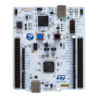
Nucleo-64 board MB1814
Brand:
ST
| Category:
Motherboard
| Size: 10 MB
Table of Contents
Figure 1. NUCLEO-H503RB Top View
1
Figure 2. NUCLEO-H503RB Bottom View
1
Features
2
Ordering Information
3
Products and Codification
3
Table 1. Ordering Information
3
Table 2. Codification Explanation
3
Development Environment
4
System Requirements
4
Development Toolchains
4
Conventions
5
Table 3. ON/OFF Convention
5
Quick Start
6
Getting Started
6
Default Board Configuration
6
Table 4. Default Jumper Configuration
6
Figure 3. Default Jumper Settings
7
Hardware Layout and Configuration
8
Figure 4. Hardware Block Diagram
8
PCB Layout
9
Figure 5. Top Layout
9
Figure 6. Bottom Layout
9
Mechanical Drawing
10
Figure 7. STM32H5 Nucleo-64 Board Mechanical Drawing (in Millimeters)
10
Embedded STLINK-V3EC
11
Description
11
Drivers
11
STLINK-V3EC Firmware Upgrade
11
Using an External Debug Tool to Program and Debug the On-Board STM32
12
Table 5. JP1 Configuration
12
Figure 8. Connecting an External Debug Tool to Program the On-Board STM32
12
Table 6. STDC14/MIPI10 Debug Connector (CN4) Pinning
13
Figure 9. STDC14/MIPI10 Connector (CN4)
13
Power Supply and Power Selection
14
Figure 10. Power Supply Input from STLINK-V3EC USB Connector with PC (5 V, 500 Ma Maximum)
14
Table 7. External Power Sources VIN (7 to 12 V)
15
Figure 11. Power Supply Input from VIN (7 to 12 V, 800 Ma Maximum)
15
Table 8. Power Supply Input from E5V (5 V, 500 Ma Maximum)
16
Table 9. External Power Source VBUS_STLK (5 V, 500 Ma)
16
Figure 12. Power Supply Input from E5V (5 V, 500 Ma Maximum)
16
Table 10. External Power Source 3V3
17
Figure 13. Power Supply Input from STLINK-V3EC USB Connector with a USB Charger (5 V, 500 Ma Maximum)
17
Figure 14. Power Supply Input from External 3V3
17
Table 11. External Power Source VBUSC (5 V, 500 Ma Maximum)
18
Figure 15. Power Supply Input from USB User Connector (5 V, 500 Ma)
18
Programming/Debugging When the Power Supply Is Not from STLINK-V3EC (STLK)
19
Clock Sources
20
LSE Clock (Low-Speed External Clock) - 32.768 Khz
20
HSE Clock (High-Speed External Clock) - 24 Mhz
20
Board Functions
21
Leds
21
Push-Buttons
21
Table 12. LED Indicators
21
Current Consumption Measurement (IDD)
22
Virtual COM Port (VCP): USART1/USART3
22
USB Full Speed (Device Mode)
22
Table 13. USART Configuration
22
Table 14. Host and Device Configurations
23
Table 15. USB Type-C ® Connector (CN3) Pinout
23
Figure 16. USB Type-C ® Connector (CN3) Front View
23
Expansion Connectors
24
ARDUINO ® uno V3
24
Figure 17. ARDUINO ® Connectors
24
Table 16. ARDUINO ® Connectors Pinout
25
ST Morpho Connector (CN7 and CN10)
26
Figure 18. ST Morpho Connectors (CN7 and CN10)
26
Table 17. Pin Assignment of the ST Morpho Connector
27
STM32H5 Nucleo-64 I/O Assignment
28
Table 18. STM32H5 Nucleo-64 I/O Assignment
28
NUCLEO-H503RB Product Information
30
Product Marking
30
NUCLEO-H503RB Product History
30
Board Revision History
30
Table 19. Product History
30
Table 20. Board Revision History
30
Federal Communications Commission (FCC) and ISED Canada Compliance
31
Statements
31
FCC Compliance Statement
31
ISED Compliance Statement
31
Revision History
32
Table 21. Document Revision History
32
Table of Contents
33
List of Tables
35
List of Figures
36
Advertisement
ST STM32H5 Application Note (26 pages)
Debug authentication (DA) for MCUs
Brand:
ST
| Category:
Microcontrollers
| Size: 1 MB
Table of Contents
Table 1. Applicable Products
1
Figure 1. Debug Authentication Interface
1
General Information
2
Table 2. Terms and Abbreviations
2
Table 3. Synthesis Table for SMT32H5 Products
3
Table 4. Synthesis Table for Stm32H7Rx/7Sx Products
3
Overview
4
Debug Authentication Provisioning Overview
4
Debug Authentication Using Password Overview
4
Debug Authentication Using Certificates Overview
4
Figure 2. Debug Authentication Using a Password
4
Figure 3. Debug Authentication Using Certificate
5
STM32 Debug Authentication Services Description
6
Discovery Service
6
Discovery Service Details
6
CLI Command for Discovery Command
6
Full Regression Service
6
Full Regression Details
6
Table 5. Discovery Service Availability
6
STM32 Series Full Regression Support
7
CLI Commands for Full Regression
7
Partial Regression Service
7
Partial Regression Service Details
7
Table 6. STM32 Series Full Regression Support
7
Partial Regression Service and EEPROM Emulation
8
Partial Regression Service and HDP Areas
8
Partial Regression Service and WRP
8
STM32 Series Partial Regression Support
8
CLI Command for Partial Regression
8
Debug Reopening Service
8
Debug Reopening Service Details
8
Table 7. STM32 Series Partial Regression Support
8
Table 8. Debug Connection Vs Product State
8
Debug Reopening and Stirot
9
STM32 Debug Reopening Support
9
Table 9. STM32 Debug Reopening Support
9
CLI Commands to Reopen Debug on STM32H5
10
CLI Commands to Reopen Debug on Stm32H7Rx/7Sx
10
Close Debug Service
10
Close Debug Details
10
STM32 Close Debug Support
11
CLI Command for Close Debug Command
11
Forced Download Service
11
Forced Download Details
11
Stm32H7Rx/7Sx Series Forced Download Support
11
CLI Command for Forced Download
11
Table 10. STM32 Close Debug Support
11
Table 11. Stm32H7Rx/7Sx Series Forced Download Support
11
Debug Authentication Activation
12
Provisioning
12
Introduction
12
Debug Authentication Using Password
12
Debug Authentication Using Certificates
12
Permission Mask
12
Debug Authentication Trigger
13
STM32 Debug Authentication Protocol Description
14
Physical Link
14
STM32 Debug Authentication Protocol Overview
14
Figure 4. DBGMCU Usage
14
Debug Authentication Using Password
15
Debug Authentication Using a Certificate Chain
15
Sequence Diagram
15
Figure 5. Debug Authentication Using Password
15
Certificates and Certificate Chains
16
Permission Masks
16
Figure 6. Debug Authentication Using a Root Certificate
16
Certificates and Product Series/Device Filtering
17
Figure 7. Example of a Forbidden Action
17
Figure 8. Example of an Authorized Action
17
Debug Authentication Ecosystem Overview
18
Debug Authentication Provisioning
18
Table 12. da Configuration Xml File Details
18
Table 13. Debug Authentication Configuration Obk File Details
18
Figure 9. Debug Authentication Ecosystem During Provisioning Phase
18
Launch Debug Authentication Service (Certificate Method)
19
Table 14. Debug Authentication Certificates Generation Xml File Details
19
Figure 10. Debug Authentication Ecosystem for Service Launch
19
STM32 Debug Authentication Restrictions
20
Debug Authentication and WWDG
20
Revision History
21
Table 15. Document Revision History
21
Table of Contents
22
List of Tables
24
List of Figures
25
ST STM32H5 Getting Started (25 pages)
Brand:
ST
| Category:
Computer Hardware
| Size: 1 MB
Table of Contents
Figure 1. Debug Authentication Interface
1
General Information
2
Table 1. Terms and Abbreviations
2
Overview
3
Debug Authentication Provisioning Overview
3
Debug Authentication Using Password Overview
3
Debug Authentication Using Certificates Overview
3
Figure 2. Debug Authentication Using a Password
3
Figure 3. Debug Authentication Using Certificate
4
STM32H5 Debug Authentication Services Description
5
Discovery Service
5
Discovery Service Details
5
CLI Command for Discovery Command
5
Full Regression Service
5
Full Regression Details
5
STM32H5 Series Full Regression Support
6
CLI Commands for Full Regression
6
Partial Regression Service
6
Partial Regression Service Details
6
Partial Regression Service and EEPROM Emulation
6
Partial Regression Service and HDP Areas
6
Partial Regression Service and WRP
6
Table 2. STM32H5 Series Full Regression Support
6
STM32H5 Series Partial Regression Support
7
CLI Command for Partial Regression
7
Debug Reopening Service
7
Debug Reopening Service Details
7
Table 3. STM32H5 Series Partial Regression Support
7
Table 4. Debug Connection Vs Product State
7
Debug Reopening and Stirot
8
STM32H5 Debug Reopening Support
8
CLI Commands for Reopen Debug Command
8
Table 5. STM32H5 Debug Reopening Support
8
Close Debug Service
9
Close Debug Details
9
STM32H5 Close Debug Support
9
CLI Command for Close Debug Command
9
Table 6. STM32H5 Close Debug Support
9
Debug Authentication Activation
10
Provisioning
10
Introduction
10
Debug Authentication Using Password
10
Debug Authentication Using Certificates
10
Permission Mask
10
Debug Authentication Trigger
11
STM32H5 Debug Authentication Protocol Description
12
Physical Link
12
STM32H5 Debug Authentication Protocol Overview
12
Figure 4. DBGMCU Usage
12
Debug Authentication Using Password
13
Debug Authentication Using a Certificate Chain
13
Sequence Diagram
13
Figure 5. Debug Authentication Using Password
13
Certificates and Certificate Chains
14
Permission Masks
14
Figure 6. Debug Authentication Using a Root Certificate
14
Certificates and Product Series/Device Filtering
15
Figure 7. Example of a Forbidden Action
15
Figure 8. Example of an Authorized Action
15
Debug Authentication Ecosystem Overview
16
Debug Authentication Provisioning
16
Table 7. da Configuration Xml File Details
16
Table 8. Debug Authentication Configuration Obk File Details
16
Figure 9. Debug Authentication Ecosystem During Provisioning Phase
16
Launch Debug Authentication Service (Certificate Method)
17
Table 9. Debug Authentication Certificates Generation Xml File Details
17
Figure 10. Debug Authentication Ecosystem for Service Launch
17
Synthesis Table
18
Table 10. Synthesis Table
18
STM32H5 Debug Authentication Restrictions
19
Debug Authentication and WWDG
19
Revision History
20
Table 11. Document Revision History
20
Table of Contents
21
List of Tables
23
List of Figures
24
Advertisement
Related Products
ST STM32H747I-EVAL
ST STM32H757I-EVAL
ST STM32H747I-DISCO
ST STM32H747XI MCU
ST STM32H7B3I-EVAL
ST STM32H7 Nucleo-144
ST STM32H735G-DK
ST STM32H753I-EVAL
ST STM32H743I-EVAL
ST STM32-MICRIUM
ST Categories
Motherboard
Computer Hardware
Microcontrollers
Control Unit
Controller
More ST Manuals
Login
Sign In
OR
Sign in with Facebook
Sign in with Google
Upload manual
Upload from disk
Upload from URL