Sign In
Upload
Manuals
Brands
SICK Manuals
Measuring Instruments
Master Data Analyzer
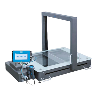
User Manuals: SICK Master Data Analyzer Compact
Manuals and User Guides for SICK Master Data Analyzer Compact. We have
1
SICK Master Data Analyzer Compact manual available for free PDF download: Operating Instructions Manual
SICK Master Data Analyzer Operating Instructions Manual (128 pages)
Track and trace systems
Brand:
SICK
| Category:
Measuring Instruments
| Size: 4 MB
Table of Contents
Table of Contents
3
1 About These Operating Instructions
7
Purpose of this Document
7
Information Depth
7
Abbreviations Used
7
Symbols Used
8
2 Safety
9
Qualified Safety Personnel
9
Applications of the System
9
Intended Use
10
General Safety Notes and Protective Measures
11
Safety Notes and Symbols
11
Additional Operating Instructions
12
General Safety Notes
12
Danger Due to Electrical Current
13
Dangers Connected with Handling of the Device
13
Risks During Transport and Installation
14
Risks During Operation
15
Protective Devices
17
Fig. 1: Protective Devices
17
Protective Equipment
18
The Operating Entity's Responsibilities
18
Work Station
18
Fig. 2: Work Station
18
Protecting the Environment
19
Disposal after Final Decommissioning
19
Power Consumption
19
3 System Description
20
Scope of Delivery
20
System Components
21
Fig. 3: System Components
21
Fig. 4: Hand-Held Scanner
21
Fig. 5: Electronic Scales
22
Fig. 6: MLG-2 Light Grids
22
Fig. 7: Measurement Gantry with Light Grids
23
Fig. 8: Wire Draw Encoder
23
Fig. 9: Controller MSC800
24
Fig. 10: Display
24
Fig. 11: IP Camera (MDA650 Image/Mda800 Image Only)
24
Fig. 12: Housing
25
Fig. 13: WLAN Module
25
The System's Operating Principle
26
Fig. 14: Measurement Process for each Operating Mode
26
Fig. 15: Marked Measurement Field on the Glass Panel
27
Fig. 16: Operating Principle - Bar Code Reading
27
Fig. 17: Operating Principle - Volume Measurement
28
Fig. 18: Operating Principle - Weighing Process
29
Fig. 19: Operating Principle - Visualization of Measurement Results
30
Project Planning
31
Status Indicators
32
Status Indicators - Light Grids
32
Fig. 20: Status Indicators - Light Grids
32
Status Indicators - Hand-Held Scanner (Only in Operating Mode with Bar Code Scanning)
33
Fig. 21: Status Indicators - Hand-Held Scanner
33
Status Indicators - Display
34
Status Indicators - IP Camera
34
Fig. 22: Status Indicators - IP Camera
34
Fig. 23: Status Indicators - Display
34
Status Indicators - Electronic Scales
35
Status Indicators - WLAN Module
35
Fig. 24: Status Indicators - WLAN Module
35
Interfaces
36
4 Transport, Assembly, and Mounting
37
Accepting the Delivery
37
Checking Delivery for Visible Transport Damage
37
Packaging
37
Transporting the MDA to Its Location of Use
38
Fig. 25: Transporting with a Lifting Device
38
Unpacking and Setting up the Device
39
Unpacking the MDA
39
Checking Delivery for Hidden Transport Damage
40
Fig. 26: Lifting the MDA from the Transport Pallet
40
Setting up the MDA
41
Fig. 27: Risk of Crushing When Settings down the MDA
41
Removing the Transport Locks
43
Fig. 28: Removing the Transport Locks on the Electronic Scales
43
Mounting
44
Mounting the WLAN Module
44
Ready to Go
44
Fig. 29: Mounting the WLAN Module
44
5 Electrical Installation
45
Connections on the MDA
46
Components Connected as Standard
46
Connections on the Controller Housing
46
Fig. 30: Hand-Held Scanner Connected as Standard
46
Fig. 31: Connections on the Controller Housing
46
Connecting the MDA to the Supply Voltage
47
Fig. 32: Connecting the MDA to the Voltage Supply
47
Connecting the MDA to the Target Network
48
Connecting the Sliding Table with Rechargeable Battery
48
Fig. 33: Connecting the MDA to the Ethernet
48
Connecting the WLAN Adapter
49
Fig. 34: Connecting the WLAN Adapter
49
6 Commissioning
50
Starting the MDA
50
Checking Operational Readiness
50
Starting up the MDA
50
Fig. 35: Checking Whether Objects Are Detected
51
Preparing the Configuration PC
52
Establishing a Connection with the Configuration PC
52
Service and Data Interface
52
Fig. 36: Connection with the Configuration PC
52
Fig. 37: Service and Data Interface
52
Installing SOPAS
53
Launching SOPAS
54
Adding the MDA to the SOPAS Project
55
Starting the Device Search
55
Loading Device Drivers into the SOPAS Project
57
Transferring the Controller to a SOPAS Project
57
Fig. 38: Loading Device Drivers into the SOPAS Project
57
Setting the Controller to Online
59
Fig. 39: Loading Standard Parameters into the SOPAS Project
59
Configuring the MDA in SOPAS
60
Incorporating the MDA Controller into the Customer's Network
61
Issuing the Data Interface IP Address
61
Testing the Server Connection
62
Storing Connection Data for the Customer Server
63
Saving Data Permanently
64
Performing a Test Run
65
Setting up the IP Camera
66
Fig. 40: Integration of the IP Camera
66
Configuring the WLAN Module
67
Fig. 41: Connecting the Configuration PC to the WLAN Module
67
7 Operation
68
Safety Information
68
Steps for Preparing for Your First Measurement
70
Adjusting the Display and Operating Position
70
Fig. 42: Adjusting the Display and Operating Position of the Monitor
70
Starting up the MDA
71
Structure of the Measurement Window
72
Moving the Measurement Gantry to a Start Position
74
Fig. 43: Measurement Gantry in Start/End Position
74
Positioning a Measuring Object
75
Fig. 44: Measuring Object on the Glass Panel
75
Fig. 45: Placing the Entire Measuring Object on the Measurement Field
75
Performing Measurements
76
Scanning the Bar Code (Only for the Operating Mode with Bar Code Scanning)
76
Starting the Measurement Process
76
Fig. 46: Scanning the Bar Code with the Hand-Held Scanner
76
Weighing the Object (Only for the Operating Mode Without Bar Code Scanning)
78
Measuring the Volume
79
Fig. 47: Moving the Measurement Gantry over the Object
79
Checking the Measurement Results
80
Reading Measurement Data
80
Checking Measurements with the 2D Display
81
Displaying the Measuring Object in a Live View
81
Transmitting Measurement Results
82
Direct Data Output if the Device Is Connected to a Server
82
Saving Measurement Data Internally (Only for Operating Mode with Bar Code Scanning)
82
Displaying the Transmission Status
83
Displaying the Transmission Status (Only for Operating Mode Without Bar Code Scanning)
84
Restoring a Server Connection Manually
85
Performing New Measurements
86
Fig. 48: Moving the Measurement Gantry to the End Position
86
Repeating Incorrect Measurements
88
Object was Positioned Incorrectly
88
Volume Measurement Without Bar Code (Only for Operating Mode with Bar Code Scanning)
89
Volume Measurement Without a Stable Weight (Only for Operating Mode Without Bar Code Scanning)
90
Performing Mobile Measurements
91
Using the Sliding Table with Rechargeable Battery
91
Configuration
92
Logging into the Configuration Area
92
Correcting the Zero Point
93
General Settings
93
Performing Teach-In
93
Selecting a Language
93
Display Settings
95
8 Maintenance and Repairs
96
Maintenance and Repairs
97
Visual Inspection for Mechanical and Electrical Damage
98
Cleaning the Light Grids
99
Fig. 49: Cleaning - Light Grids
99
Cleaning the Display
100
Fig. 50: Cleaning - Touchscreen Display
100
Cleaning the Glass Panel
101
Cleaning the Internal Housing Area
101
Fig. 51: Cleaning - Internal Housing Area (Preliminary Work)
102
Fig. 52: Cleaning - Internal Housing Area (Removing the Glass Panel)
102
Cleaning the IP Camera's Dust Shield Housing
103
Replacing Components
104
Replacing the Display
105
Replacing the Hand-Held Scanner (Only in Operating Mode with Bar Code Scanning)
105
Fig. 53: Replacing Components - Hand-Held Scanner
105
Fig. 54: Replacing Components - Display (Removing the Cables)
105
Replacing the Glass Panel
106
Fig. 55: Replacing Components - Display (Dismantling/Mounting)
106
Fig. 56: Cleaning - Internal Housing Area (Preliminary Work)
107
Fig. 57: Cleaning - Internal Housing Area (Removing the Glass Panel)
107
Replacing the IP Camera
108
Fig. 58: Replacing Components: IP Camera - Removing the Dust Shield Housing
108
Fig. 59: Replacing Components: IP Camera -Unplugging the Ethernet Cable from the IP Camera
108
Fig. 60: Replacing Components: IP Camera - Removing the IP Camera from the
108
Replacing the WLAN Module
109
Fig. 61: Replacing Components - WLAN Module
109
9 Fault Diagnosis
110
Response to Faults
110
Fault Indicators
110
Dealing with Status Messages
110
Status Indicator on the Display
110
Overview of Status Messages
111
Status Indicators for Components
114
SICK Support
115
10 Technical Specifications
116
Data Sheets
116
Data Sheet for the Idm26X Hand-Held Scanner (Wired)
116
System Data Sheet
116
IP Camera Axis M3005-V
117
WLAN Ethernet Port Adapter FL WLAN EPA
117
Dimensional Drawings
118
Spare Parts List
118
Fig. 62: Dimensional Drawings of the MDA650/MDA800
118
Data Interface
119
11 Appendix
120
List of Tables
120
Appendix 11
121
List of Figures
121
Keywords Index
123
Advertisement
Advertisement
Related Products
SICK ALIS
SICK airWiper
SICK Master Data Analyzer Vision
SICK AOS102
SICK AOS104
SICK AFS60 PROFINET
SICK ATM60-C4H13X13
SICK AHS36 CANopen Inox
SICK AHS/AHM36 SAE J1939
SICK Gas Cell AGK848
SICK Categories
Accessories
Security Sensors
Measuring Instruments
Scanner
Barcode Reader
More SICK Manuals
Login
Sign In
OR
Sign in with Facebook
Sign in with Google
Upload manual
Upload from disk
Upload from URL