Sign In
Upload
Manuals
Brands
Royal Enfield Manuals
Motorcycle
Classic 500 2009
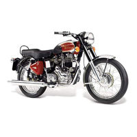
Royal Enfield Classic 500 2009 Manuals
Manuals and User Guides for Royal Enfield Classic 500 2009. We have
1
Royal Enfield Classic 500 2009 manual available for free PDF download: Service Manual
Royal Enfield Classic 500 2009 Service Manual (230 pages)
Brand:
Royal Enfield
| Category:
Motorcycle
| Size: 8.5 MB
Table of Contents
Important Notice
3
Preparation for Service
3
Safety
3
Use of Genuine Spare Parts
3
Table of Contents
4
Engine Dismantling
4
Section Four
4
Section Six
4
Section Three
4
Section Two
4
Section Two
6
General
6
Four Stroke Cycle Operation
7
Unit Construction Engine
7
Salient Features of the Unit Construction
7
Basic Terminology of IC Engines
8
Clearance Volume
8
Cubic Capacity / Displacement
8
Stroke
8
Total Volume
9
Compression Ratio
9
Volumetric Efficiency
9
Horse Power (Hp or Ps)
9
Ihp
10
Fhp
10
Bhp
10
Torque
10
Ignition Timing
11
Idling Speed
11
Gear Ratio
11
Final Drive Ratio
11
Technical Specifications
12
Engine and Engine Systems
12
Identification of Chassis & Engine No.
15
List of Special Tools & Its Application
16
Control Cables & Wiring Harness Routing
21
Under Tank and Seat Top View
21
Under Tank Lh View
21
Under Tank Rh View
21
General Vehicle Information
22
Harness Routing Steering Rh
22
Magneto Wires Routing
22
Plug Wire Routing
22
Handle Bar Instrument Panel & Cable Routing
23
Horn Wire Routing
23
Fuse Carriers Arrangement (Classic 500)
23
Fuse Carriers Arrangement (Classic 350)
23
Throttle Body Mounting
24
Tail Lamp & Trafficator Wires Routing
24
Ecu Mounting
24
Tci Unit Mounting
24
Section Three 03
25
Service Data
25
Section Three
25
Wear Limits
26
Service Limits of Components
26
New Min
26
New Min.
30
Clutch Spring Length
31
Lay Shaft 1St Gear Inner Diameter
31
Lay Shaft 2Nd Gear Inner Diameter
31
New Max.
31
Pivot Cam Plate Outside Diameter
31
Classic 500 Classic 350 New Min. 0.06
32
Clutch Cable -Free Play
32
Drive Chain : Slackness
32
Duplex Chain - Length Across 21 Pins
32
Rear Sprocket Chain Pull off
32
Brake Lining Thickness
33
Drive Chain Length Across 21 Pins
33
New Min.
33
Sprocket
33
Wheel Rim: Face out / Run out
33
Caliper Piston Outer Diameter
34
Front Fork Assembly Spring : Length
34
Main Tube - Run out
34
Master Cylinder Piston OD
34
New Max. 0.07
34
Service Limit
35
Spark Plug Gap
35
Swing Arm Bush & Spacer
35
Tyre Tread : Depth
35
Periodical Maintenance Chart
36
Air Filter Cleaning
37
Engine Oil
37
Oil Level Check
37
Spark Plug Cleaning
37
Draining Procedure
38
Fitting Procedure
38
Oil Change
38
Rear Wheel Chain Slackness Adjustment
39
Brake Cam Greasing
40
Brake Pedal Play Adjustment
40
Pedal Free Play 20 to 30 MM
40
Rear Brake Switch Adjustment
40
Front Fork
41
Rear Shock Absorbers Adjustment
41
Disc Brake Fluid Level Check
42
Steering Play Adjustment
42
Clutch Cable Free Play
43
Steering Ball Race Lubrication
43
Adjustment at Handle Bar End (Classic 500)
44
Primary Chain Tension Adjustment
44
Throttle Cable Assy Replacement (Classic 500)
44
Throttle Cable Play Adjustment
44
Checking Procedure of Throttle Position Sensor (Tps) Cable
45
Throttle Cable Assy Replacement (Classic 350)
46
CV Carburetor Drain and Tuning Procedure
47
Engine Compression Test
47
Float Height Adjustment
47
Decarbonising Cylinder Head
48
Cylinder Head and Valves
49
Inspect the Valve Seat Face
49
Service Limit
49
Valve Seat Inspection
49
Valve Seat Refacing
50
The Parts Detail of Cylinder Head Assembly
51
Valve Timing Cum Eccentric Cam Spindle
52
Eccentric Cam Spindle Adjustment
52
Battery Electrolyte Level Checking
53
Specific Gravity Checking
53
Terminal Cleaning
53
Section Four
54
Engine Lubrication System
55
Upper Cylinder Lubrication
55
Lower Cylinder Lubrication
55
Lubrication Oil
56
Oil Pump : Trochoid Type
57
What Is Hydraulic Tappet
58
Benefit of Hydraulic Tappet
58
Cut Section View of Rhvl
58
Working Principle
59
Precautionary Measures
59
Auto Decompressor
60
Auto Decompressor - Working Principle
60
Benefits of Auto Decompressor
60
Electric Starting System & Sprag Mechanism
61
Auto Chain Tensioner Assembly
62
Engine Breather System
63
Inlet Manifold & Throttle Body
64
Crankcase RH - Coverside View
65
Crankcase LH - Inside View
67
Crankcase RH - Inside View
69
Description Qty
70
Flange Hex Nut - M8
70
Stud, M8 X
70
Engine Cover RH
71
Crankcase LH - Coverside View
73
Hex Socket Head Cap Screw, M5 X
74
Jack Shaft
74
Needle Bearing
74
Stud M6 X 106
74
Engine Cover LH
75
Gear Train Assembly
77
Gear Shifting / Kick Starter
79
Cylinder Head, Barrel, Piston & Crankshaft
81
Crank Shaft Assy.
81
Piston Assy.
81
Damper Pad Position Details
83
Engine
54
Section Five
84
Engine Dismantling Procedure
84
Engine Disassembly
85
Dismantling Procedure
86
Clutch Cable Removal
87
Removal of Throttle Cable
87
Removal of Throttle Body
87
Removal of Silencer and Exhaust Pipe
88
Battery Removal
88
Removal of E-Start Motor
89
Removal of Drive Chain
90
Removal of Side Stand
90
Removal of Rear Brake Switch
90
Engine Oil Drain
91
Cylinder Head Assembly
91
Removal of Valves
92
Cylinder Barrel Sub Assy.
93
Removal of Cover Rh Sub Assembly
94
Components for Dismantling from Crankcase Rh
97
Removal of Rotor Assembly
97
Dismantling Procedure of Auto Decompressor
98
Dismantling Cover Lh Sub Assembly
102
Components for Dismantling from Crankcase Lh
103
Removal of Clutch Assy
103
Dismantling of Clutch Assembly
104
Gear Train Removal
110
Dismantling of Layshaft Sub Assembly
112
Layshaft Sub Assembly
112
Main Shaft Sub Assembly
113
Dismantling of Mainshaft Sub Assembly
113
Removal of Sleeve Gear Assembly
114
Removal of Sleeve Gear Sub Assembly
114
Removal of Kick Starter Assembly
114
Removal of Kick Starter Sub Assembly
115
Vital Parts
116
Bearings
116
Gears / Sprockets
116
Unidirectional Fittings List
117
Torque Specification - Engine
118
Engine Assembly
120
Assembly of Engine Bearings
120
Crankcase Lh
120
Crankcase Rh
121
Assembling of Gear Rocker Shaft Sub Assembly
125
Assembling of Layshaft Sub Assembly
126
Assembling of Mainshaft Sub Assembly
127
Assembly of Clutch
135
Assembling Procedure of Auto Decompressor
140
Valve Timing
141
Assembly Procedure of Cam Gears
141
Piston Sub Assembly
145
Cleaning
145
Cylinder Barrel
147
Cylinder Head
147
Valve Leakage Test
151
Engine Mangement System
154
Section Six
154
Engine Dismantling Inspection & Assembly
84
Section Six 06
155
Section Eight
155
Function of Components in EMS
156
Electronic Control Unit (Ecu)
156
Alternator
156
Throttle Body Assembly
156
Ecu Pin Configuration
157
Fuel Injector
158
The Advantages of Fuel Injection
158
Exploded View of Fuel Injector
158
Assembled between Throttle Body and Cylinder Head
158
Fuel Pump Module
159
Low Fuel Sensor
159
Malfunction Indicator Lamp (Mil)
159
Assembled on the Headlamp Casing
159
Throttle Body Module
160
Assembled between Air Filter and Inlet Manifold
160
Throttle Position Sensor (Tps)
161
The Ecu Uses the Throttle Valve Position to Know
161
Manifold Pressure Sensor (Map)
161
Manual Bi Starter
161
Engine Oil Temperature Sensor
162
Crank Position Sensor
162
Assembled on the Cylinder Head
162
Assembled on the Engine RH Cover
162
Roll over Sensor
163
Assembled under the Seat
163
Level 1 Visual
164
Level 2 Test Pin
164
Level 3 Dol
165
Instructions (Do’s & Don’ts) on EMS
166
Trouble Shooting - EMS
167
Engine Management System (EMS)
155
Engine Management System - Functional Diagram
155
Section Six 07
169
CV Carburetor
169
CV Carburetor - Exploded View
170
Function of Carburetor
171
Carburetor Performs Three Important Functions
171
Carburetor Removal
171
Dismantling Proceedure - Carburetor
172
Torque Specification
173
Assembling Proceedure - Carburetor
174
Installation of Carburetor
175
Carburetor Tuning Procedure
176
Carburetor Maintenance
177
Procedure for Setting Idling Speed and Co%
177
Maintenance Tips
177
Service Guidelines
177
Trouble Shooting
178
Chassis, Wheels & Brakes
179
Torque Specification - Chassis
180
Front Wheel Removal
182
Front Wheel Bearings Removal
182
Disc Brake
183
Draining Old Brake Fluid
183
General Instructions
183
Overhauling Caliper and Master Cylinder
184
Bleeding Procedure
185
Normal Method
185
Bleeding Proceedure
186
Reverse Bleeding Method
186
Disassembly of Master Cylinder
187
Reassembly of Master Cylinder
189
Disassembly of Wheel Caliper
191
Caliper Assembly
193
Wheel Disc Inspection
196
Rear Wheel Removal
196
Brake Drum Assembly
197
Suspension & Steering
199
Section Nine
199
Front Fork Disassembly
201
Removal of Fork Seals
201
Front Fork Assembly
202
Steering Disassembly
202
Reassembly of Steering
203
Gas Filled Shock Absorber
204
Section Ten
204
Removal and Assembly of Rear Shock Absorber
205
Swing Arm
205
Recharging of Shock Absorbers
205
Center Stand
208
Electricals
209
Electricals
210
Electrical Symbols
210
Battery Construction
210
Initial Charge (New Battery) Electrolyte
211
Temperature of Electrolyte
212
Soaking Period
212
Charging a New Battery
212
Recharging Used Batteries
212
Maintenance
213
Spark Plug Maintenance
214
Specific Gravity
214
Check Voltage with Voltmeter
214
Measuring Instrument
215
Starter Coil
215
Pulsar Coil
215
Ignition Coil
215
Checking Procedure of Electrical Components
216
Suppressor Cap - M14
216
Battery
216
Relay Starter
216
E- Starter Motor
217
Rr Unit
217
IC Flasher
217
Electrical Parts Inspection
218
Clutch Switch
218
Starter Switch
218
Starter Relay
218
Complete Wiring Diagram - Classic 500
219
Complete Wiring Diagram - Classic 350
220
Trouble Shooting - Electricals
221
Trouble Shooting
222
Section Eleven
222
Advertisement
Advertisement
Related Products
Royal Enfield Thunderbird 500 2018
Royal Enfield Bullet 500 2017
Royal Enfield Bullet 500CC
Royal Enfield 500 BULLET 1955
Royal Enfield 500 TWIN 1957
Royal Enfield 500 TWIN 1956
Royal Enfield 500 TWIN 1955
Royal Enfield 500 BULLET 1956
Royal Enfield 500 BULLET 1959
Royal Enfield 500 BULLET 1960
Royal Enfield Categories
Motorcycle
Diagnostic Equipment
Motorcycle Accessories
Control Unit
Engine
More Royal Enfield Manuals
Login
Sign In
OR
Sign in with Facebook
Sign in with Google
Upload manual
Upload from disk
Upload from URL