Sign In
Upload
Manuals
Brands
Rotax Manuals
Engine
IM-912 ULS 3
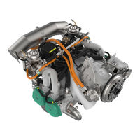
User Manuals: Rotax IM-912 ULS 3 Aircraft Engine
Manuals and User Guides for Rotax IM-912 ULS 3 Aircraft Engine. We have
1
Rotax IM-912 ULS 3 Aircraft Engine manual available for free PDF download: Installation Manual
Rotax IM-912 ULS 3 Installation Manual (136 pages)
Brand:
Rotax
| Category:
Engine
| Size: 4 MB
Table of Contents
1 Table of Contents
3
2 Index
7
3 Preface
9
Remarks
9
Engine Serial Number
9
ROTAX Authorized Distributors for Aircraft Engines
9
4 Safety
11
Repeating Symbols
11
Safety Information
11
Instruction
13
Technical Documentation
14
5 List of the Effective
17
6 Table of Amendments
19
7 Description of Design
21
Designation of Type
21
Standard Engine Design
21
Auxiliary Equipment
22
Engine Components, Engine Views, Definition of Main Axes
24
8 Technical Data
27
Operating Limits
27
Installation Dimensions
28
Weight
28
Centre of Gravity of Engine and Standard Equipment
29
Moments of Inertia
29
9 Preparations for Engine Installation
31
Transport
31
State of Delivery
31
Engine Preservation
31
Protective Covering
32
10 Engine Suspension and Position
33
Definition of Attachment Points
34
Permissible Fitting Positions
35
General Directives for Engine Suspension
38
11 Exhaust System
39
Requirements on the Exhaust System
40
Operating Limits
41
General Directives for Exhaust-System
42
Data for Optional Components of Exhaust System
43
12 Cooling System
47
Description of the System
47
Operating Limits
48
BRP-Rotax
48
Coolant Types
49
Check Cooling System - Efficiency of the Cooling System
50
1) Measurement of Cylinder Head Temperature and Exit Temperature
50
Determination of Operating Limits, Coolant and Necessary Modification on Radiator Installation
52
Requirements on the Cooling System
54
Size and Position of Connections
55
Water Inlet Bend
57
Feasible Location of Radiator
58
Overflow Bottle
59
General Directives for the Cooling System
61
Coolant Capacity
63
Cooling Air Ducting
63
1)General Directives for Ducting of the Cooling Air
64
Data for Optional Components of Cooling System
65
13 Lubrication System
67
Description of the System
67
Limits of Operation
68
Checking of the Lubrication System
69
1) Measuring of the Vacuum
69
2) Measuring of the Pressure in the Crankcase
70
Requirements on the Oil- and Venting Lines
71
Connecting Dimensions and Location of Connections
72
1) Oil Circuit (Engine)
72
2) Oil Tank
75
Feasible Position and Location of the Oil Tank
76
Feasible Position and Location of the Oil Cooler
77
General Notes on Oil Cooler
77
Filling Capacity
77
Purging of Lubrication System
78
Inspection for Correct Priming of Hydraulic Valve Tappets
79
Replacement of Components
80
Data for Optional Components of Oil System
81
14 Fuel System
83
Description of System
83
Operating Limits
85
Requirements of the Fuel System
86
Connecting Dimensions, Location of Joints and Directives for Installation
87
1) Fuel Manifold
87
2) Fuel Pressure Control
88
3) Check Valve
89
15 Carburetor
91
Requirements on the Carburetor
91
1) Drainage Piping on Airbox and Drip Trays
92
Connections for Bowden-Cable Actuation and Limit Load
94
Requirements on Cable Actuation
96
Requirements on the Throttle Lever
97
16 Air Intake System
99
Operating Limits
99
Requirements on the Air Intake System
100
1) Requirements on the Intake Air Ducting
100
2) Airfilter
100
3) Airbox
101
Data for Optional Components of Air Intake System
104
17 Electric System
107
Requirements on Circuit Wiring
107
1) Electromagnetic Compatibility (EMC/EMI)
108
Wiring Diagram
108
Technical Data and Connection of the Electric Components
110
1) Integrated Generator
110
2) Rectifier-Regulator
110
3) Electronic Modules
112
4) Ignition Switches (MAG Switch)
112
5) Electric Starter
114
6) Starter Relay
115
7) External Alternator (Optional Extra)
116
8) Connection of the Electric Rev-Counter (Tachometer)
118
9) Battery
119
10) Capacitor (Option Electric Fuel Pump)
119
11) Starting Equipment at the Electronic Modules (Optional Extra)
119
18 Propeller Drive
121
Technical Data
121
19 Vacuum Pump
123
Technical Data
123
20 Hydraulic Governor for Constant Speed Propeller
125
Technical Data
125
21 Connections for Instrumentation
127
Sensor for Cylinder Head Temperature
127
Sensor for Oil Temperature
128
Oil Pressure Sensor
129
Mechanical Rev Counter (Tach Drive)
130
Monitoring of the Intake Manifold Pressure
131
Air Temperature in the Airbox (Optional)
132
22 Preparations for Trial Run of Engine
133
Advertisement
Advertisement
Related Products
Rotax SI-912 i-001R5
Rotax 377
Rotax 377 UL
Rotax SI-916 i-003R1
Rotax SI-915 i-003R2
Rotax SI-912 i-004R3
Rotax 122
Rotax 125 DD2 MAX EVO
Rotax 125 JUNIOR MAX evo
Rotax 125 Max
Rotax Categories
Engine
Lubrication systems
Outboard Motor
Boat
Aircrafts
More Rotax Manuals
Login
Sign In
OR
Sign in with Facebook
Sign in with Google
Upload manual
Upload from disk
Upload from URL