Sign In
Upload
Manuals
Brands
Rigol Manuals
Test Equipment
DS70504
Rigol DS70504 Manuals
Manuals and User Guides for Rigol DS70504. We have
3
Rigol DS70504 manuals available for free PDF download: User Manual, Manual, Quick Manual
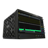
Rigol DS70504 User Manual (321 pages)
Brand:
Rigol
| Category:
Test Equipment
| Size: 20.36 MB
Table of Contents
Table of Contents
3
1 Safety Requirement
17
General Safety Summary
17
Safety Notices and Symbols
19
Measurement Category
19
Ventilation Requirement
20
Working Environment
20
Care and Cleaning
22
Environmental Considerations
22
Keep Hands Clear
23
2 Product Features
24
3 Document Overview
26
4 Quick Start
28
General Inspection
28
Appearance and Dimensions
28
Figure 4.1 Front View
28
To Prepare for Use
29
To Connect to AC Power
29
Figure 4.2 Side View
29
Turn-On Checkout
30
Figure 4.3 to Connect to AC Power
30
To Set the System Language
31
To Connect the Probe
31
Figure 4.4 to Connect the Passive Probe
31
Figure 4.5 to Connect the Probe Head to the PA of the Active Probe
32
Function Inspection
33
Figure 4.6 to Connect the Active Probe
33
Figure 4.7 to Use the Compensation Signal
34
Figure 4.8 Waveform Signal
34
Probe Compensation
35
Product Overview
35
Figure 4.9 Probe Compensation
35
Front Panel Overview
36
Figure 4.10 Front Panel
36
Rear Panel Overview
38
Figure 4.11 Rear Panel
38
User Interface
41
Figure 4.12 User Interface
41
Secondary 3.5-Inch Touch Screen
43
Figure 4.13 Smart Quick-Responsive Keyboard Interface
44
Figure 4.14 Flip Screen Adjustment Interface
46
Touch Screen Gestures
47
Tap
47
Pinch&Stretch
48
Drag
48
Figure 4.15 Tap Gesture
48
Figure 4.16 Pinch&Stretch Gesture
48
Parameter Setting Method
49
Figure 4.17 Drag Gesture
49
Figure 4.18 English Input Interface
50
Figure 4.19 Chinese Input Interface
51
Figure 4.20 String Keypad
53
Figure 4.21 Numeric Keypad
54
To Use the Built-In Help System
55
Figure 4.22 Help Information
55
To View the Option Information and the Option Installation
56
5 To Set the Vertical System
58
To Enable or Disable the Analog Channel
58
Figure 5.1 Vertical Menu for Channel
58
To Adjust the Vertical Scale
59
To Adjust the Vertical Offset
61
Channel Coupling
62
BW Limit
62
Input Impedance
63
Table 5.1 BW Limit
63
Waveform Invert
64
Figure 5.2 Input Impedance Modification
64
Probe
65
Figure 5.3 Waveform Invert
65
Figure 5.4 Probe Setting Menu
65
Figure 5.5 RP7000/PVA7000/PVA8000 Series Probe Setting Menu
66
Table 5.2 Probe Ratio
66
Amplitude Unit
68
Figure 5.6 Selfcal
68
Bias
69
Channel Delay
69
Channel Label
70
Figure 5.7 Zero Offset
70
6 To Set the Horizontal System
71
Figure 6.1 Horizontal System Menu
71
To Adjust the Horizontal Time Base
72
To Adjust the Horizontal Position
72
Delayed Sweep
73
Figure 6.2 Delayed Sweep Mode
74
7 To Set the Sample System
75
Acquisition Mode
75
Figure 7.1 Horizontal System Menu
75
Sampling Mode
77
Sample Rate
77
Memory Depth
78
Figure 7.2 Memory Depth
79
Anti-Aliasing
80
Horizontal Expansion
80
XY Mode
81
Figure 7.3 XY Setting Menu
81
Figure 7.4 Measurement Schematic Diagram of Phase Deviation
82
8 To Trigger the Oscilloscope
84
Trigger Source
84
Trigger Level
85
Trigger Mode
86
Figure 8.1 Schematic Diagram of the Acquisition Memory
86
Trigger Coupling
87
Trigger Holdoff
88
Figure 8.2 Trigger Holdoff
88
Noise Rejection
89
Trigger Type
89
Edge Trigger
89
Figure 8.3 Edge Trigger Setting Menu
90
Pulse Trigger
91
Figure 8.4 Positive Pulse Width/Negative Pulse Width
92
Figure 8.5 Pulse Trigger Setting Menu
93
Slope Trigger
95
Figure 8.6 Positive Slope Time/Negative Slope Time
95
Figure 8.7 Slope Trigger Setting Menu
96
Video Trigger
98
Figure 8.8 Video Trigger Setting Menu
99
Table 8.1 Video Standard
100
Pattern Trigger
101
Figure 8.9 Pattern Trigger
102
Figure 8.10 Pattern Trigger Setting Menu
102
Duration Trigger
104
Figure 8.11 Duration Trigger
104
Figure 8.12 Duration Trigger Setting Menu
105
Timeout Trigger
107
Figure 8.13 Timeout Trigger
107
Figure 8.14 Timeout Trigger Menu
108
Runt Trigger
109
Figure 8.15 Runt Trigger
110
Figure 8.16 Runt Trigger Setting Menu
110
Window Trigger
112
Figure 8.17 Window Trigger Setting Menu
113
Delay Trigger
115
Figure 8.18 Delay Trigger
115
Figure 8.19 Delay Trigger Setting Menu
116
Setup/Hold Trigger
118
Figure 8.20 Setup/Hold Trigger
119
Figure 8.21 Setup/Hold Trigger Setting Menu
120
Nth Edge Trigger
122
Figure 8.22 Nth Edge Trigger
122
Figure 8.23 Nth Edge Trigger Setting Menu
123
RS232 Trigger (Option)
124
Figure 8.24 Schematic Diagram of RS232 Protocol
125
Figure 8.25 RS232 Trigger Setting Menu
125
I2C Trigger (Option)
127
Figure 8.26 Schematic Diagram of I2C Protocol
127
Figure 8.27 I2C Trigger Setting Menu
128
Figure 8.28 bin Format Setting
130
Figure 8.29 Hex Format Setting
130
SPI Trigger (Option)
131
Figure 8.30 Sequential Chart of SPI Bus
132
Figure 8.31 SPI Trigger Setting Menu
132
CAN Trigger (Option)
135
Figure 8.32 Data Frame Format of the CAN Bus
135
Figure 8.33 CAN Trigger Setting Menu
136
Figure 8.34 Sample Position
137
Flexray Trigger (Option)
139
Figure 8.35 Frame Format of Flexray Bus
139
Figure 8.36 Flexray Trigger Setting Menu
140
LIN Trigger (Option)
142
Figure 8.37 Data Frame Format of the LIN Bus
142
Figure 8.38 LIN Trigger Setting Menu
143
Figure 8.39 Sample Position
144
I2S Trigger (Option)
145
Figure 8.40 Sequential Chart of I2S Bus
146
Figure 8.41 I2S Trigger Setting Menu
146
MIL-STD-1553 Trigger (Option)
149
Figure 8.42 Formats of the Command Word, Data Word, and Status Word of
150
Figure 8.43 MIL-STD-1553 Trigger Setting Menu
151
Trigger Output Connector
154
9 Math Operation
155
Figure 9.1 Math Operation Menu
156
Arithmetic Operation
157
Figure 9.2 Waveform Display Window of the Operation Results
157
Figure 9.3 Arithmetic Operation Menu
158
Figure 9.4 Operation Result Display Window
159
Function Operation
160
Figure 9.5 Function Operation Menu
161
Figure 9.6 Operation Result Display Window
162
FFT Operation
163
Figure 9.7 FFT Operation Menu
164
Figure 9.8 FFT Operation Window
165
Table 9.1 Window Function
166
Figure 9.9 Peak Search
168
Logic Operation
169
Figure 9.10 Logic Operation Menu
169
Table 9.2 Logic Operation
170
Figure 9.11 Operation Result Display Window
171
Digital Filter
172
Figure 9.12 Digital Filter Menu
173
Figure 9.13 Operation Result Display Window
174
10 Measure
176
Measurement Parameter
176
Time Parameters
177
Figure 10.1 Time Parameters
177
Count Values
178
Delay and Phase Parameters
179
Figure 10.2 Delay and Phase Parameters
179
Voltage Parameters
181
Figure 10.3 Voltage Parameters
181
Other Parameters
182
To Select the Measurement Item
183
Figure 10.4 Vertical Measurement Items
184
Figure 10.5 Horizontal Measurement Items
185
Measurement Settings
186
Figure 10.6 Other Measurement Items
186
Figure 10.7 Measurement Settings
187
Remove the Measurement Results
190
Auto Measurement
190
Cursor Measurement
192
Figure 10.8 Cursor
192
Manual Mode
193
Figure 10.9 Cursor Measurement Result
193
Figure 10.10 Manual Mode Setting Menu
194
Track Mode
196
Figure 10.11 Manual Cursor Measurement Example
196
Figure 10.12 Track Mode Setting Menu
197
Figure 10.13 Track Measurement (before Horizontal Expansion)
198
XY Mode
199
Figure 10.14 Track Measurement (after Horizontal Expansion)
199
Figure 10.15 XY Mode
199
11 Digital Voltmeter (DVM)And Frequency Counter
201
Digital Voltmeter (DVM)
201
Measurement Settings
202
Figure 11.1 DVM Setting Menu
202
Remove the Measurement
203
Frequency Counter
203
Measurement Settings
204
Figure 11.2 Frequency Counter Setting Menu
204
Reset Statistics
205
Remove the Measurement
205
12 Real-Time Eye Analysis (Option)
206
Figure 12.1 Eye Diagram Setting Menu
206
To Enable or Disable the Eye Analysis Function
207
To Select the Source of the Eye Diagram
207
Threshold Settings
207
Figure 12.2 Eye Measurement Result
207
To Set Clock Recovery
208
To Set the Data Rate
209
Eye Measurement Result
209
Figure 12.3 Diagram of Eye Measurement Parameters
210
To Set the Display-Related Parameters
211
13 Jitter Analysis (Option)
212
Figure 13.1 Jitter Setting Menu
212
To Enable or Disable the Jitter Function
213
To Set Parameters
213
To View the Jitter Measurement
214
14 Reference Waveform
216
To Enable Ref Function
216
Figure 14.1 Reference Waveform Menu
216
To Set the Reference Waveform
217
To Set the Ref Waveform Display
217
Export and Import Operation
218
Figure 14.2 Disk Management Interface
219
15 Pass/Fail Test
221
To Enable or Disable the Pass/Fail Test Function
221
Figure 15.1 Pass/Fail Test Menu
221
To Start or Stop the Pass/Fail Test Operation
222
To Select the Source
222
Mask
222
To Set the Output Form of the Test Results
223
To Enable or Disable the Display of the Statistics of the Test Results
224
16 RTSA (Option)
225
Basic Settings
225
Figure 16.1 Basic Setting Menu
225
Freq
226
Span
227
Ampt
228
Peak Search
229
Figure 16.2 Peak Search Menu
229
17 Protocol Decoding
231
Parallel Decoding
231
Figure 17.1 Schematic Diagram of Parallel Decoding
232
Figure 17.2 Parallel Decoding Menu
232
Clock Setting (CLK)
233
Bus Setting
233
Table 17.1 Bus Setting
233
Display-Related Setting
234
Event Table
234
RS232 Decoding (Option)
235
Figure 17.3 Parallel Decoding Event Table
235
Figure 17.4 Schematic Diagram of RS232 Serial Bus
236
Figure 17.5 Schematic Diagram of Negative Logic
236
Source Setting
237
Figure 17.6 RS232 Decoding Menu
237
To Set Data Package
238
Display-Related Setting
239
Event Table
239
I2C Decoding (Option)
240
Figure 17.7 RS232 Decoding Event Table
240
Figure 17.8 I2C Serial Bus
240
Source Setting
241
Figure 17.9 I2C Decoding Menu
241
Display-Related Setting
242
Event Table
242
Figure 17.10 I2C Decoding Event Table
243
Figure 17.11 SPI Serial Bus
244
Figure 17.12 SPI Decoding Menu
244
SPI Decoding (Option)
244
To Set the Source
245
To Set Mode and Data
245
Display-Related Setting
246
Event Table
247
Figure 17.13 SPI Decoding Event Table
247
LIN Decoding (Option)
248
Signal Configuration
248
Figure 17.14 LIN Decoding Menu
248
Display-Related Setting
249
Event Table
249
Figure 17.15 LIN Decoding Event Table
250
CAN Decoding (Option)
251
Signal Configuration
251
Figure 17.16 CAN Decoding Menu
251
Figure 17.17 Sample Position
252
Display-Related Setting
253
Event Table
253
Figure 17.18 CAN Decoding Event Table
254
Figure 17.19 Flexray Decoding Menu
255
Flexray Decoding (Option)
255
Signal Configuration
256
Figure 17.20 Sample Position
256
Display-Related Setting
257
Event Table
257
Figure 17.21 Flexray Decoding Event Table
257
I2S Decoding (Option)
258
Source Setting
259
Figure 17.22 I2S Decoding Menu
259
Bus Setting
260
Display-Related Setting
260
Event Table
261
Figure 17.23 I2S Decoding Event Table
261
1553B Decoding (Option)
262
Figure 17.24 1553B Decoding Menu
262
To Set the Data Channel Source and the Threshold
263
Display-Related Setting
263
Event Table
263
Figure 17.25 1553B Decoding Event Table
264
18 Bus Analysis (Option)
266
ETH Bus Analysis
266
Figure 18.1 ETH Bus Analysis Configuration Menu
266
USB Bus Analysis
267
Figure 18.2 USB Bus Analysis Configuration Menu
268
19 Multi-Pane Windowing
270
Figure 19.1 "Add Window" Interface
270
20 Waveform Recording and Playing
272
Common Settings
272
Figure 20.1 Waveform Recording Interface
272
Record Options
273
Play Option
274
Figure 20.2 Play Operation Interface
275
21 Display Control
277
Display Type
277
Figure 21.1 Display Setting Menu
277
Persistence Time
278
Intensity
278
Figure 21.2 Vector Display
278
To Set the Screen Grid
279
Display Setting
279
Show Scale
279
Color Grade
279
Waveform Freeze
279
22 Storage
281
To Enter the Storage Menu
281
To Save a File
281
Save Image
281
Figure 22.1 Image Saving Setting Menu
282
Save Wave
283
Figure 22.2 Waveform Saving Setting Menu
284
Save Setup
285
Figure 22.3 Setup Saving Setting Menu
286
Binary Data Format (.Bin)
287
Table 22.1 File Header
287
Table 22.2 Waveform Header
288
Table 22.3 Waveform Data Header
289
Load a File
290
Figure 22.4 Load Setting Menu
291
System Upgrade
291
Disk Management
292
Figure 22.5 Upgrade Menu
292
Figure 22.6 Disk Management Interface
293
Factory Settings
294
Table 22.4 Factory Settings
299
23 System Utility Function Setting
302
I/O Setting
302
Object Missing
304
About this Oscilloscope
305
Other Setting
305
Selfcal
306
Option List
306
Figure 23.1 Self-Calibration Menu
306
Quick Settings
307
Figure 23.2 Quick Settings Menu
307
Self-Check
309
Figure 23.3 Key Test Interface
309
Figure 23.4 Touch Screen Test Interface
310
Figure 23.5 Touch-Enabled Gesture Operation Interface
311
Figure 23.6 Board Test Interface
312
24 Remote Control
313
Remote Control Via USB
314
Remote Control Via LAN
314
Remote Control Via GPIB
315
Figure 24.1 Search for the Available Device
316
Figure 24.2 Confirm the Available Device
316
25 Troubleshooting
317
26 Appendix
319
Appendix A: Options and Accessories
319
Appendix B Warranty
320
Advertisement
Rigol DS70504 Manual (43 pages)
Digital Oscilloscope
Brand:
Rigol
| Category:
Test Equipment
| Size: 2.13 MB
Table of Contents
Table of Contents
3
Safety Requirement
7
General Safety Summary
7
Safety Notices and Symbols
8
Specification
10
Document Overview
12
Overview
14
Test Preparations
14
Test Result Record
15
Specifications
16
Performance Verification Test
17
Impedance Test
17
Specification
17
Test Connection Diagram
18
Test Procedures
18
Test Record Form
19
DC Gain Accuracy Test
20
Specification
20
Test Connection Diagram
20
Test Procedures
20
Test Record Form
23
DC Offset Accuracy Test
26
Specification
26
Test Connection Diagram
26
Test Procedures
26
Test Record Form
27
Bandwidth Test
29
Specification
29
Test Connection Diagram
29
Test Procedures
30
Test Record Form
31
Timebase Accuracy Test
31
Specification
31
Test Connection Diagram
32
Test Procedures
32
Test Record Form
33
Random Noise Test
33
Test Procedures
34
Test Record Form
34
Appendix: Test Record Form
36
Rigol DS70504 Quick Manual (27 pages)
High-End Digital Oscilloscope
Brand:
Rigol
| Category:
Test Equipment
| Size: 3.78 MB
Table of Contents
Safety Requirement
3
General Safety Summary
3
Safety Notices and Symbols
3
Care and Cleaning
4
Document Overview
5
General Inspection
6
Product Overview
7
Front Panel Overview
7
Rear Panel Overview
8
User Interface
9
To Prepare for Use
10
To Connect to AC Power
10
Turn-On Checkout
10
To Set the System Language
11
To Connect the Probe
11
Function Inspection
14
Probe Compensation
15
Touchscreen Gestures
17
To Use the Built-In Help System
20
Parameter Setting Method
21
Fuse Replacement
23
Remote Control
24
More Product Information
25
Advertisement
Advertisement
Related Products
Rigol DS7034
Rigol DS7054
Rigol DS7024
Rigol DS7014
Rigol DS70000 Series
Rigol DS7000 Series
Rigol DS70304
Rigol DS1042MD
Rigol DS1102M
Rigol DS1102Z-E
Rigol Categories
Test Equipment
Measuring Instruments
Power Supply
Portable Generator
Inverter
More Rigol Manuals
Login
Sign In
OR
Sign in with Facebook
Sign in with Google
Upload manual
Upload from disk
Upload from URL