Sign In
Upload
Manuals
Brands
Ricoh Manuals
All in One Printer
A265
Ricoh A265 Manuals
Manuals and User Guides for Ricoh A265. We have
3
Ricoh A265 manuals available for free PDF download: Service Manual
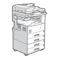
Ricoh A265 Service Manual (860 pages)
Brand:
Ricoh
| Category:
All in One Printer
| Size: 13.82 MB
Table of Contents
Table of Contents
11
Important Safety Notices
25
Laser Safety
26
Overall Information
27
Overall Machine Information
29
Specifications
31
Overall Machine Information
31
Machine Configuration
35
System Components
35
Copier Options
37
Fax and Printer Options
37
Installable Option Table
37
Scanner Option
37
Paper Path
38
Mechanical Component Layout
39
Electrical Component Descriptions
41
Drive Layout
44
Copy Process
45
Overview
45
Board Structure
47
Overview
47
Description
48
Detailed Descriptions
49
Detailed Section Descriptions
51
Scanning
51
Overview
51
Scanner Drive
52
Original Size Detection in Platen Mode
53
Image Processing
55
Overview
55
Sbu (Sensor Board Unit)
56
Auto Image Density
57
In the IPU
57
In the SBU
57
Service Mode" Original Types
57
Ipu (Image Processing Unit)
58
Overview
58
Image Processing Modes
59
Image Processing Path
61
SP Modes for each Image Processing Step
62
Auto Shading
68
Black Line Erase Compensation
68
White Line Erase Compensation
68
Main Scan Magnification/Reduction
70
Mirroring for ADF Mode
70
Filtering
71
Scanner Gamma
74
Gradation Processing
75
ID Gamma (Γ) Correction
75
Line Width Correction
77
Memory Controller and Enhanced Memory Board (Emb)
78
Fine Character and Image (FCI)
79
Printer Gamma Correction
79
Video Control Unit (Vcu)
79
Laser Exposure
80
Overview
80
Auto Power Control (Apc)
81
Ld Safety Switch
82
Overview
83
Photoconductor Unit (Pcu)
83
Drive
84
New Pcu Detection
85
Drum Charge
86
Overview
86
Charge Roller Voltage Correction
87
Correction for Environmental Conditions
87
ID Sensor Pattern Production Timing
88
Drum Charge Roller Cleaning
89
Development
90
Overview
90
Drive
91
Developer Mixing
92
Development Bias
93
Toner Bottle Replenishment Mechanism
94
Toner Supply
94
Toner Supply Mechanism
95
Overview
96
Toner Density Control
96
Toner Density Measurement
98
Toner Density Sensor Initial Setting
98
Toner Supply Determination
98
Toner Supply Reference Voltage (Vref) Determination
98
Vsp/Vsg Detection
98
Toner Supply Motor on Time Determinations
99
ID Sensor
100
TD Sensor
100
Toner Near End Detection
100
Toner Near End/End Detection and Recovery
100
Toner Supply in Abnormal Sensor Conditions
100
Toner End Detection
101
Toner End Recovery
101
Toner Near End Recovery
101
Drum Cleaning
102
Drum Cleaning and Toner Recycling
102
Toner Recycling
103
Overview
104
Paper Feed
104
Paper Feed Drive Mechanism
105
Paper Feed and Separation Mechanism
106
Paper Lift Mechanism
107
Paper End Detection
108
Paper Height Detection
109
Feed Pressure Adjustment for Paper Size
110
Overview
110
Paper Size Thresholds
110
Effect of the Amount of Remaining Paper
111
Feed Pressure Adjustment
111
Paper Size Detection
113
Special Paper Setting
114
End Fence
115
Side and End Fences
115
Side Fences
115
Paper Registration
116
Image Transfer and Paper Separation
117
Overview
117
Image Transfer Current Timing
118
Paper Separation Mechanism
119
Transfer Roller Cleaning
119
Image Fusing and Paper Exit
120
Overview
120
Fusing Drive and Release Mechanism
121
Fusing Entrance Guide Shift Mechanism
122
Cleaning Mechanism
123
Pressure Roller
123
Fusing Temperature Control
124
Temperature Control
124
Fusing Lamp Control
125
Overheat Protection
126
Paper Exit
126
Energy Saver Modes
127
Overview
127
Energy Saver Mode
128
Entering the Energy Saver Mode
128
Return to Stand-By Mode
128
What Happens in Energy Saver Mode
128
Entering the Low Power Mode
129
Low Power Mode
129
Return to Stand-By Mode
129
What Happens in Low Power Mode
129
Auto off Mode
130
Disabling Auto off Mode
130
Entering Auto off Mode
130
Returning to Stand-By Mode
130
What Happens in Auto off Mode
130
Entering Night Stand-By and Night Modes
131
Night Mode
131
What Happens in Night Stand-By and Night Modes
131
Returning to Stand-By Mode
132
Installation Procedure
135
Installation Requirements
135
Environment
135
Machine Level
135
Minimum Space Requirements
136
Power Requirements
137
Copier Installation
138
Power Sockets for Peripherals
138
Installation Flow Chart
139
Accessory Check
140
Installation Procedure
141
Paper Tray Unit Installation
145
Accessory Check
145
Lct Installation
148
Accessory Check
148
Auto Reverse Document Feeder Installation
151
Accessory Check
151
Installation Procedure
151
Interchange Unit Installation
154
Component Check
154
Installation Procedure
155
1-Bin Tray Unit Installation
157
Component Check
157
Installation Procedure
157
Shift Tray
160
Component Check
160
Installation Procedure
160
By-Pass Feed Unit Installation
162
Components Check
162
Installation Procedure
162
Duplex Unit Installation
164
Accessory Check
164
Installation Procedure
165
Bridge Unit Installation
167
Accessory Check
167
Installation Procedure
167
1,000-Sheet Finisher Installation
169
Copier Feature Expander Installation
172
Platen Cover Installation
173
Key Counter Installation
174
Anti-Condensation Heater
176
Tray Heater
177
Tray Heater (Optional Paper Tray Unit)
179
Tray Heater (Optional Lct)
182
Service Tables
185
General Caution
187
Pcu (Photoconductor Unit)
187
Scanner Unit
187
Transfer Roller Unit
187
Fusing Unit
188
Laser Unit
188
Others
188
Paper Feed
188
Service Program Mode
189
Service Program Access Procedure
189
Service Program Mode Operation
189
Accessing Copy Mode from Within an SP Mode
190
How to Select the Program Number
190
To Input a Value or Setting for an SP Mode
190
Service Program Mode Tables
191
Test Pattern Printing (Sp4-417 and Sp5-902)
246
Input Check (Sp5-803)
247
Input Check Table
247
Output Check (Sp5-804)
252
Output Check Table
252
Copy Jam History Display (Sp7-903)
254
Smc Data Lists (Sp5-992)
255
Original Jam History Display (Sp7-905)
256
Memory All Clear (Sp5-801)
257
Using a Flash Memory Card
257
Without Using a Flash Memory Card
257
Program Download (SP5-827)
258
Program Upload/Download
258
Program Upload (SP5-826)
259
Nvram Data Download
260
NVRAM Data Download (SP5-825)
260
NVRAM Data Upload (SP5-824)
261
(Sp4-301)
262
Aps and Platen/Df Cover Sensor Output Display
262
Df Aps Sensor Output Display (Sp6-901)
263
Nip Band Width Measurement
264
Display Language (Sp5-808)
265
Serial Number Input (Sp5-811)
265
ID Sensor Error Analysis (Sp2-221)
266
User Tools
267
How to Enter and Exit User Tools
267
System Setting Table
267
User Tools Table
267
Copy Setting Table
268
Leds
269
Bicu
269
Iob
269
Special Tools and Lubricants
269
Lubricants
269
Special Tools
269
Rom History
270
Rom History - Bicu
270
Preventive Maintenance
273
Preventive Maintenance Schedule
275
Pm Table
275
By-Pass Unit A899
302
Replacement and Adjustment
279
Exposure Glass
281
Replacement and Adjustment
281
Scanner Unit
281
Scanner Exterior/Operation Panel
282
Lens Block Assembly
283
Original Size Sensors/Lamp Stabilizer
284
Exposure Lamp
285
Scanner Motor
286
Scanner Wires
287
Caution Decal Locations
290
Laser Unit
290
Laser Unit
291
Ld Unit
292
Polygon Mirror Motor
292
Laser Synchronization Detector
293
Pcu
294
Photoconductor Unit (Pcu)
294
Transfer Roller Unit
295
Transfer Unit
295
Image Density Sensor
296
Fusing Unit
297
Fusing/Exit
297
Thermistor
297
Thermofuse
298
Hot Roller and Fusing Lamp
299
Pressure Roller/Cleaning Roller
300
Paper Exit Sensor/Paper Overflow Sensor
301
Paper Feed
302
Paper End Sensor
303
Paper Tray Lift Motors
304
Registration Clutch
305
Paper Feed Clutches
306
Relay Clutches
307
Paper Size Detector/Special Paper Sensor
308
Registration Sensor
309
Relay Sensors
310
Pcbs and Other Items
311
I/O Board
312
Main Motor
313
Copy Adjustments: Printing/Scanning
315
Blank Margin
316
Parallelogram Image Adjustment
317
Scanning
318
Standard White Density Adjustment
319
Adf Image Adjustment
320
Troubleshooting
323
Sc Code Descriptions
324
SC194: IPU White Level Detection Error
326
SC546: Unstable Fusing Temperature
331
SC620: Communication Error between IOB and ADF
332
SC760: ADF Gate Abnormal
336
SC921: EMB (Copier Feature Expander) Hardware Error
337
SC980: Program Loading Error
337
SC990: Communication Error between BICU and IOB
337
SC999: Program Version Error
337
Paper Feed Troubleshooting
338
Skewed Image
339
Adjust the Toner Density Control
340
Dirty Background
340
If the Toner Density Is too High
340
If the Toner Density Is too Low
340
Toner Density
340
Electrical Component Defects
341
Sensors
341
Switches
343
Blown Fuse Conditions
344
Auto Recirculating Document Feeder A858
345
Overall Machine Information
347
Specifications
347
Mechanical Component Layout
348
Electrical Component Layout
349
Electrical Component Description
350
Drive Layout
351
Detailed Section Descriptions
352
Original Size Detection
352
Pick-Up and Separation
355
Original Transport and Exit
356
Single-Sided Originals
356
Double-Sided Originals
357
Original Trailing Edge Sensor
358
Stamp
359
Lt Sideways (Single-Sided Original Mode)
360
Timing Charts
360
Lt Sideways Stamp Mode
361
Lt Sideways (Double-Sided Original Mode)
362
Lt Sideways Stamp Mode
363
Condition of Jam Detection
364
Overall Electrical Circuit
365
Paper Tray Unit A860
393
Duplex A896
436
Df Exit Table and Cover
366
Replacement and Adjustment
366
Original Feed Unit
367
Left Cover
368
Pick-Up Roller
369
Feed Belt
370
Separation Roller
371
Original Set/Original Reverse Sensor
372
Original Length, Widthsensor Board and Trailing Edge Sensor
373
Df Feed Clutch/Df Pick-Up Solenoid/ Transport Df Feed Motors
374
Registration Sensor
375
Stamp Solenoid and Original Exit Sensor
376
Overall Machine Information
379
Mechanical Component Layout
380
Electrical Component Layout
381
Electrical Component Description
382
Drive Layout
383
Detailed Description
384
Paper Lift Mechanism
385
Paper End Detection
387
Paper Height Detection
388
Paper Size Detection
390
Side and End Fences
391
Replacement and Adjustment
392
Tray Main Board Replacement
393
Relay Clutch Replacement
394
Upper Paper Feed Clutch Replacement
395
Lower Paper Feed Clutch Replacement
396
Lift Motor Replacement
397
Paper End Sensor Replacement
398
Paper Size Switch Replacement
399
Overall Machine Information
403
Mechanical Component Layout
404
Electrical Component Layout
405
Electrical Component Descriptions
406
Detailed Section Descriptions
407
Reverse Roller and Pick-Up Roller Release
408
Tray Lift
409
Near End/End Detection
410
Right Tray Side Fence
411
Right Tray Paper End Detection
412
Replacement and Adjustment
413
Changing the Tray Paper Size
414
Tray Lift Motor
415
Tray Motor
416
Paper Feed Clutch and Relay Clutch
417
Paper Feed Unit
418
Upper Limit, Right Tray Paper End, and Relay Sensors
419
Rear Fence Motor
420
Pick-Up/Paper Feed/Reverse Rollers
421
Overall Machine Information
425
Electrical Component Layout
426
DETAILED Descriptions
427
Paper Size Detection
428
Replacement and Adjustment
429
Paper Size Sensor Board
430
Paper Feed Clutch
431
Overall Machine Information
435
Mechanical Component Layout
436
Drive Layout
437
Detailed Description
438
Replacement and Adjustment
439
1 Bin Tray Unit A898
444
Overall Machine Information
443
Mechanical Component Layout
444
Electrical Component Layout
445
Electrical Component Description
446
Drive Layout
447
Detailed Descriptions
448
Up to A4 Lengthwise/Lt Lengthwise
449
Feed in and Exit Mechanism
450
Replacement and Adjustment
451
Entrance Sensor Replacement
452
Exit Sensor Replacement
453
Overall Information
457
Mechanical Component Layout
458
Electrical Component Layout
459
Detailed Section Descriptions
460
Replacement and Adjustment
461
Junction Gate Mechanism
470
Bridge Unit Drive Motor Replacement
471
Tray Exit Sensor Replacement
472
Overall Machine Information
475
Component Layout
476
Detailed Section Descriptions
477
Primary Mechanisms
478
Half Turn Detection
479
Replacement and Adjustment
480
Tray Motor and Half Turn Sensor Replacement
481
Overall Machine Information
485
Mechanical Component Layout
486
Electrical Component Layout
487
Electrical Component Descriptions
488
Drive Layout
490
Detailed Descriptions
491
Jogger Unit Paper Positioning Mechanism
492
Exit Guide Plate Open/Close Mechanism
493
Stapler
494
Feed out Mechanism
495
Shift Tray Up/Down Mechanism
496
Shift Tray Side-To-Side Mechanism
497
Jam Conditions
498
Timing Charts
499
Staple Mode (A4 Sideways, 2 Sheets/2 Sets)
500
Service Table
501
Replacement and Adjustment
502
Lower Left Cover
503
Entrance Sensor Replacement
504
Exit Sensor Replacement
505
Stack Height Sensor Replacement
506
Positioning Roller Replacement
507
Stapler Replacement
508
Rom History
509
Overall Machine Information
512
Software
513
Detailed Section Descriptions
514
Scanner Functions
516
Installation Procedure
517
Service Table
520
Downloading New Software
522
Error Messages During the Software Download
523
Replacement and Adjustment
524
Troubleshooting
525
Leds
526
Overall Machine Information/Detailed Section Descriptions
530
1 Overall Machine Information
536
Specifications
536
Features List
537
Capabilities of Programmable Items
540
Overall Machine Control
541
System Control
541
Memory Back-Up
542
Power Distribution and Control
542
Video Data Path
543
Transmission
543
Reception
545
Pc Fax Communication
546
Scanning and Printing
548
2 Detailed Section Descriptions
550
Automatic Service Calls
550
Service Call Conditions
550
Effective Term of Service Calls
552
Periodic Service Call
552
Pm Call
552
Page Split Transmission (Book Transmission)
553
Scanning Features
553
Image Rotation before Transmission
554
Create Margin Transmission
556
Paper Size Selection
557
Printing Features
557
Just Size Printing
563
Reduction for Journal Printing
563
Journal Line Type Sort Printing
564
Printing Lists & Reports on A5/Hlt Size Paper
564
Reduction of the Sample Image on Reports
565
Fax Communication Features
566
Sep/Sub/Pwd/Sid
566
Jbig Compression
568
V.8/V.34 Protocol
569
Line Type Change
573
Fcu
574
Pcbs
574
Ncu (Us)
576
Ncu (Europe/Asia)
577
Sg3 Board
578
Exfunc Board
579
3 Installation
580
Cautions
580
Fax Unit
580
Flow Chart
581
Fax Option Type 270 Installation
582
G3 Interface Unit Type 270
586
Optional Units
586
Isdn Option Type 270
590
Pc Fax Expander (Pcfe)
593
Fax Function Expander (Exfunc)
595
Expansion Memory (Exmem) Board
597
Handset
598
4 Service Tables
600
Bit Switch Programming (Function 01)
600
How to Enter and Exit the Fax Service Mode
600
Service Level Functions
600
System Parameter Lists (Function 02)
601
Error Code Display (Function 03)
603
Fcu Rom Version Display (Function 02)
603
Modem Program Version Display (Function 02)
603
Service Monitor Report (Function 04)
603
G3 Protocol Dump List (Function 05)
604
G4 Protocol Dump List (Function 05)
604
Pc Protocol Dumplist (Function 05)
605
Ram Display and Rewrite (Function 06)
605
Ncu Parameters (Function 06)
606
Ram Dump (Function 06)
606
Fcu Reboot
607
Ram Clear (Function 07)
607
Service Station Fax Number (Function 09)
607
Modem Test (Function 11)
608
Serial Number (Function 10)
608
Dtmf Test (Function 11)
609
Memory Test (Function 11)
610
Ringer Test (Function 11)
610
Diu Test (Function 11)
611
File Printout (Function 13)
611
Data Transfer (Function 16)
612
Journal Printout (Function 14)
612
Usage Log Printout (Function 15)
612
Sg3-V34 (Function 17)
613
Bit Switches
616
System Switches
616
Scanner Switches
630
Printer Switches
635
Communication Switches
640
G3 Switches
651
Sg3 Switches
659
Ncu Parameters
666
Dedicated Transmission Parameters
677
Programming Procedure
677
Parameters
678
Service Ram Addresses
682
5 Preventive Maintenance
700
Pm Table
700
Special Tools and Lubricants
700
Removal and Replacement
702
Fcu
702
Precaution
702
Removal
702
Sram Data Restore from Fcu
704
Sram Data Restore from Flash Card Backup
705
Ncu
708
Fcu Rom Download
709
Rom Update
709
Fcu Rom Upload
711
Sg3 Board Rom Download
713
Sg3 Board Modem Rom Download
714
Sram Backup to a Flash Memory Card
715
Sram Data Backup and Restore
715
Sram Restore from a Flash Memory Card
716
7 Troubleshooting
718
Error Codes
718
Fax Sc Codes
727
Overview
727
Sc1201
727
Sc1207
727
Fax Sc Code Table
728
Rom History
729
Table of Contents
733
1 Installation
735
Installation Procedure
735
User Level Programming
738
Service Level Programming
739
2 Service Tables and Procedures
741
Service Level Functions
741
Bit Switches
742
G4 Internal Switches
742
G4 Parameter Switches
750
Dedicated Transmission Parameters
755
3 Troubleshooting
757
Error Codes
757
D-Channel Layer Management
758
D-Channel Link Layer
758
D-Channel, Layer 1
758
B-Channel Link Layer
759
D-Channel Network Layer
759
B-Channel Network Layer
760
Transport Layer
760
Session Layer
761
Document Layer
762
Presentation Layer
762
G4Ccu Status Codes
763
Layer 1 (Physical Layer)
763
Layer 2 (Link Layer)
763
Network Layer (Layer 3)
764
Session Layer, Document Control Layer (Layer 5)
764
Session Layer, Session Control Layer (Layer 5)
764
Transport Layer (Layer 4)
764
Leds
765
Back-To-Back Test
766
Table of Contents
769
1 Overall Machine Information
771
Specifications
771
General Specifications
771
Supported Paper Sizes
772
Software Accessories
773
Printer Drivers
773
Service Tools
773
Utility Software
773
Machine Layout
774
Block Diagram
775
2 Detailed Section Descriptions
777
Copier, Fax or Printer
777
Display Priority
777
Engine Functions
777
Image Data Processing
777
Print Priority and Interleaving
777
Interleave
778
Auto Tray Select
779
Controller Functions
779
Paper Size/Type Detection and Selection
779
Paper Source Selection
779
By-Pass Tray
780
Manual Tray Select
780
Tray Lock
780
Output Tray Selection
781
Paper Size Mismatch
781
Collation (Sort)
782
Duplex Printing
783
Stapling
783
Proof Print
784
Hdd (Optional)
785
Job Reset
785
Menu Reset
785
Reset Operations
785
System Reset
785
3 Installation Procedures
787
Printer Controller
787
Hard Disk (Hdd)
791
Network Interface Board (Nib)
793
Postscript DIMM
795
Memory (Sdram DIMM)
797
Service Program Mode Overview
799
Sp Mode Table
799
Service Menu
800
Service Summary
802
Hdd Test
804
Hdd Format
805
Firmware Update
807
Error Recovery
809
Other Tests
810
Led Display
814
Fatal Errors
815
Advertisement
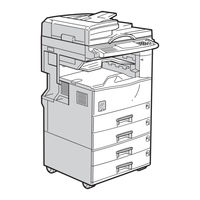
Ricoh A265 Service Manual (325 pages)
Brand:
Ricoh
| Category:
All in One Printer
| Size: 6 MB
Table of Contents
Table of Contents
4
Overall Machine Information
18
Specifications
18
Machine Configuration
22
System Components
22
Installable Option Table
24
Copier Options
24
Fax and Printer Options
24
Scanner Option
24
Paper Path
25
Mechanical Component Layout
26
Electrical Component Descriptions
28
Drive Layout
31
Copy Process
32
Overview
32
Board Structure
34
Overview
34
Description
35
Detailed Section Descriptions
36
Scanning
36
Overview
36
Scanner Drive
37
Original Size Detection in Platen Mode
38
Image Processing
40
Overview
40
Sbu (Sensor Board Unit)
41
Auto Image Density
42
In the SBU
42
In the IPU
42
Service Mode" Original Types
42
Ipu (Image Processing Unit)
43
Overview
43
Image Processing Modes
44
Image Processing Path
46
SP Modes for each Image Processing Step
47
Auto Shading
53
White Line Erase Compensation
53
Black Line Erase Compensation
53
Scanner Gamma
54
Main Scan Magnification/Reduction
55
Mirroring for ADF Mode
55
Filtering
56
ID Gamma (Γ) Correction
60
Gradation Processing
60
Line Width Correction
62
Memory Controller and Enhanced Memory Board (Emb)
63
Video Control Unit (Vcu)
64
Fine Character and Image (FCI)
64
Printer Gamma Correction
64
Laser Exposure
65
Overview
65
Auto Power Control (Apc)
66
Ld Safety Switch
67
Photoconductor Unit (Pcu)
68
Overview
68
Drive
69
New Pcu Detection
70
Drum Charge
71
Overview
71
Charge Roller Voltage Correction
72
Correction for Environmental Conditions
72
ID Sensor Pattern Production Timing
73
Drum Charge Roller Cleaning
74
Development
75
Overview
75
Drive
76
Developer Mixing
77
Development Bias
78
Toner Supply
79
Toner Bottle Replenishment Mechanism
79
Toner Supply Mechanism
80
Toner Density Control
81
Overview
81
Toner Density Sensor Initial Setting
83
Toner Density Measurement
83
Vsp/Vsg Detection
83
Toner Supply Reference Voltage (Vref) Determination
83
Toner Supply Determination
83
Toner Supply Motor on Time Determinations
84
Toner Supply in Abnormal Sensor Conditions
85
ID Sensor
85
TD Sensor
85
Toner Near End/End Detection and Recovery
85
Toner Near End Detection
85
Toner Near End Recovery
86
Toner End Detection
86
Toner End Recovery
86
Drum Cleaning and Toner Recycling
87
Drum Cleaning
87
Toner Recycling
88
Paper Feed
89
Overview
89
Paper Feed Drive Mechanism
90
Paper Feed and Separation Mechanism
91
Paper Lift Mechanism
92
Paper End Detection
93
Paper Height Detection
94
Feed Pressure Adjustment for Paper Size
95
Overview
95
Paper Size Thresholds
95
Feed Pressure Adjustment
96
Effect of the Amount of Remaining Paper
96
Paper Size Detection
98
Special Paper Setting
99
Side and End Fences
100
Side Fences
100
End Fence
100
Paper Registration
101
Image Transfer and Paper Separation
102
Overview
102
Image Transfer Current Timing
103
Transfer Roller Cleaning
104
Paper Separation Mechanism
104
Image Fusing and Paper Exit
105
Overview
105
Fusing Drive and Release Mechanism
106
Fusing Entrance Guide Shift Mechanism
107
Pressure Roller
108
Cleaning Mechanism
108
Fusing Temperature Control
109
Temperature Control
109
Fusing Lamp Control
110
Overheat Protection
111
Paper Exit
111
Energy Saver Modes
112
Overview
112
Energy Saver Mode
113
Entering the Energy Saver Mode
113
What Happens in Energy Saver Mode
113
Return to Stand-By Mode
113
Low Power Mode
114
Entering the Low Power Mode
114
What Happens in Low Power Mode
114
Return to Stand-By Mode
114
Auto off Mode
115
Entering Auto off Mode
115
What Happens in Auto off Mode
115
Returning to Stand-By Mode
115
Disabling Auto off Mode
115
Night Mode
116
Entering Night Stand-By and Night Modes
116
What Happens in Night Stand-By and Night Modes
116
Returning to Stand-By Mode
117
Installation Procedure
118
Installation Requirements
118
Environment
118
Machine Level
118
Minimum Space Requirements
119
Power Requirements
120
Copier Installation
121
Power Sockets for Peripherals
121
Installation Flow Chart
122
Accessory Check
123
Installation Procedure
124
Paper Tray Unit Installation
128
Accessory Check
128
Lct Installation
131
Accessory Check
131
Auto Reverse Document Feeder Installation
134
Accessory Check
134
Installation Procedure
134
Interchange Unit Installation
137
Component Check
137
Installation Procedure
138
1-Bin Tray Unit Installation
140
Component Check
140
Installation Procedure
140
Shift Tray
143
Component Check
143
Installation Procedure
143
By-Pass Feed Unit Installation
145
Components Check
145
Installation Procedure
145
Duplex Unit Installation
147
Accessory Check
147
Installation Procedure
148
Bridge Unit Installation
150
Accessory Check
150
Installation Procedure
150
1,000-Sheet Finisher Installation
152
Copier Feature Expander Installation
155
Platen Cover Installation
156
Key Counter Installation
157
Anti-Condensation Heater
159
Tray Heater
160
Tray Heater (Optional Paper Tray Unit)
162
Tray Heater (Optional Lct)
165
Service Tables
168
General Caution
168
Pcu (Photoconductor Unit)
168
Transfer Roller Unit
168
Scanner Unit
168
Laser Unit
169
Fusing Unit
169
Paper Feed
169
Others
169
Service Program Mode
170
Service Program Mode Operation
170
Service Program Access Procedure
170
Accessing Copy Mode from Within an SP Mode
171
How to Select the Program Number
171
To Input a Value or Setting for an SP Mode
171
Service Program Mode Tables
172
Test Pattern Printing (Sp4-417 and Sp5-902)
227
Input Check (Sp5-803)
228
Input Check Table
228
Output Check (Sp5-804)
233
Output Check Table
233
Copy Jam History Display (Sp7-903)
235
Smc Data Lists (Sp5-992)
236
Original Jam History Display (Sp7-905)
237
Memory All Clear (Sp5-801)
238
Using a Flash Memory Card
238
Without Using a Flash Memory Card
238
Program Upload/Download
239
Program Download (SP5-827)
239
Program Upload (SP5-826)
240
Nvram Data Download
241
NVRAM Data Download (SP5-825)
241
NVRAM Data Upload (SP5-824)
242
Ricoh A265 Service Manual (26 pages)
Brand:
Ricoh
| Category:
All in One Printer
| Size: 0.32 MB
Table of Contents
A265/A267 Service Manual
2
Table of Contents
2
Installation Procedure
5
Service Tables
6
Preventive Maintenance
7
Replacement and Adjustment
7
Troubleshooting
8
Overall Machine Information
10
Paper Tray Unit a
10
2 Detailed Section Descriptions
11
Large Capacity Tray a
11
Duplex a
12
Shift Tray
13
Interchange Unit B
12
Bridge Unit a
13
Shift Tray Unit B
13
Service Tables
14
Finisher a
14
Overview
15
Scanner Kit a
15
Table of Contents
16
1 Overall Machine Information
17
Specifications
17
Drive
22
Scanner Option
24
Advertisement
Advertisement
Related Products
Ricoh A267
Ricoh A283
Ricoh A284
Ricoh A207
Ricoh A206
Ricoh A204
Ricoh A214
Ricoh A292
Ricoh A293
Ricoh A230
Ricoh Categories
All in One Printer
Printer
Digital Camera
Copier
Printer Accessories
More Ricoh Manuals
Login
Sign In
OR
Sign in with Facebook
Sign in with Google
Upload manual
Upload from disk
Upload from URL