Sign In
Upload
Manuals
Brands
Piper Manuals
Aircrafts
Navajo PA-31
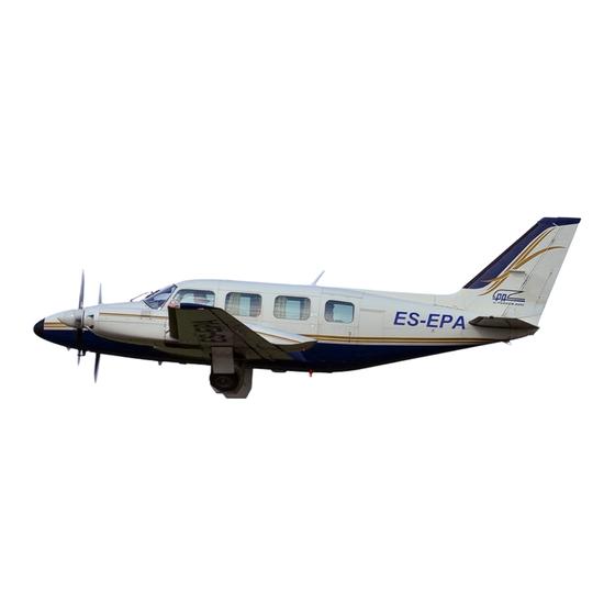
Piper Navajo PA-31 Utility Aircraft Manuals
Manuals and User Guides for Piper Navajo PA-31 Utility Aircraft. We have
1
Piper Navajo PA-31 Utility Aircraft manual available for free PDF download: Service Manual
Piper Navajo PA-31 Service Manual (1106 pages)
Brand:
Piper
| Category:
Aircrafts
| Size: 52 MB
Table of Contents
Table of Contents
3
Aerofiche Card no
5
Grid no
5
Table of Contents
7
1A20
20
Inspection
81
Alternator Output Check
103
Inspection Report
105
Handling and Servicing
20
Structures
107
Aerofiche Card no
107
Table of Contents
109
Cargo Door
142
Removal of Cargo Door
142
Installation of Cargo Door
142
Cargo Door Latch Assembly
144
Removal of Cargo Door Latch Assembly
144
Installation and Adjustment of Cargo Door Latch Assembly
144
Wing Locker Doors
142
Pilot Door
144
Removal of Pilot Door
144
Installation of Pilot Door
146
Weather Strip and Sealing Instructions of Pilot Door
146
1G2
146
Adjustment of Pilot Door
148
1G4
148
Shoulder Harness Inertia Reel Adjustment (OPT)
148
1G5
149
Balancing Definitions
149
Aileron Balancing Procedure (Aileron P/N 40200-00. 40200-01 and 40200-37)
149
Balance Data
150
Elevator Control System Friction Measurement
157
Control Surface Balancin
149
Installation of Rudder Balance Weight Anchor Nut
167
Structural Repairs
167
Fiberglass Repairs
171
Fiberglass Touch-Up and Surface Repairs
171
Fiberglass Fracture and Patch Repairs
172
Thermoplastic Repairs
173
List of Materials (Thermoplastic Repair)
174
Safety Walk Repair
178
Surface Preparation
178
Application of Liquid Safety Walk Compound
181
Surface Preparation for Pressure Sensitive Safety Walk
181
1H13
181
Radome Boot
182
1H14
182
List of Materials
182
Inspection of Radome Boot
182
Preparation and Installation of Radome Boot
182
Radome Erosion Shield
183
List of Materials
183
Section V Surface Controls
188
Control Surface Travel and Cable Tension
192
Standard Service Procedures
194
Control Column Assembly
194
Removal of Control Column Assembly
194
Installation of Control Column
198
Troubleshooting
194
Aileron Controls
201
Removal of Aileron Control Cables
201
Installation of Aileron Control Cables
204
Removal of Aileron Bellcrank Assembly
205
Installation of Aileron Bellcrank Assembly
205
Rigging and Adjustment of Aileron Controls
205
Aileron Trim Controls
207
Removal of Aileron Trim Assembly
207
Installation of Aileron Trim Assembly
208
Removal of Aileron Trim Assembly (Wing)
208
Installation of Aileron Trim Assembly (Wing)
208
Removal of Aileron Trim Sender Assembly
209
Installation of Aileron Trim Sender Assembly
209
Rigging and Adjustment of Aileron Trim
209
Rigging and Adjustment of Aileron Trim Sender and Indicator
210
Elevator Controls
210
Removal of Elevator Control Cables
210
Installation of Elevator Control Cables
211
Removal of Elevator Bellcrank Assembly
211
Elevator Trim Controls
215
Removal of Elevator Trim Assembly
215
Installation of Elevator Trim Assembly
217
Installation of Elevator Trim Assembly (Elevator)
218
Removal of Elevator Trim Sender Assembly
219
Installation of Elevator Trim Sender Assembly
219
Rigging and Adjustment of Elevator Trim
219
Rigging and Adjustment of Elevator Trim Sender and Indicator
222
Removal of Elevator Trim Assembly (Elevator)
218
Removal of Pedal Assembly
222
Installation of Pedal Assembly
223
Rudder and Steering Pedal Assembly
222
Rudder Controls
225
Removal of Rudder Control Cables
225
Installation of Rudder Control Cables
228
Removal of Rudder Horn
228
Installation of Rudder Horn
228
Rigging and Adjustment of Rudder Controls
228
Rudder Trim Controls
230
Installation of Rudder Trim Assembly
230
Removal of Rudder Trim Assembly
230
Removal of Rudder Trim Assembly (Rudder)
231
Installation of Rudder Trim Assembly (Rudder)
231
Removal of Rudder Trim Sender Assembly
231
Installation of Rudder Trim Sender Assembly
232
Rigging and Adjustment of Rudder Trim
232
Rigging and Adjustment of Rudder Trim Sender and Indicator
232
Trim Drum
233
Wrapping the Trim Drum
233
Wing Flap Controls (Dukes System) (S/N 31-5 to 31-7812129 Inclusive)
235
Fabricated Bellcrank Rigging Tool
279
Fabricated Rudder Rigging Tool
281
1L17
281
2A9
285
2E4
285
POWER PLANT (PA-31 Turbo)
285
Schematic Diagram of Hydraulic System (Ozone 2930-5 and -7) or (Wiebel 2135-1 and -3)
286
Landing Gear Selector Mechanism. Serial Nos. 31-5 Thru
286
Landing Gear Selector Mechanism. Serial Nos. 31-512 and up
286
7-10A. Landing Gear Circuit Diagram (S/N 31-185 and Up)
287
Main W Heel Assembly
287
Nose W Heel Assembly
287
W Heel Brake Assembly (30-68 and 30-68A)
287
7-16B. W Heel Brake Assembly
287
Brake Master Cylinder Assembly
287
7-19A. Nose Gearwear Limits
287
7-19B. Main Gear Wear Limits
287
Fabricated Tool, Checking Main Gear Toe-In Adjustment
287
Contact Points
288
Engine Timing Marks
288
Removing Spring from Lead Assembly
288
Assembly Tool
288
Using Assembly Tool
288
Cutting Metallic Braid from End of Lead
288
Unbraiding Metallic Shielding
288
Measuring Wire from Top of Ferrule
288
Installing Grommet over Lead Assemblies
288
Lead Assembly Installed in Grommet
288
Coupling Torques
289
Inspection and Repair. Hydraulic Pump
289
Leading Particulars. Hydraulic Power Pack (Ozone)
289
Leading Particulars. Hydraulic Power Pack (Wiebel Tool)
289
Propeller Specifications (PA-31-300)
289
Propeller Specifications (PA-31-310 and -325)
289
Propeller Specifications (PA-31-325)
289
Troubleshooting Chart (Engine) and (Turbocharger)
289
Turbocharger Installation Torque Values in Inch-Pounds
289
VIII-Ia
289
Schematic Diagram of Hydraulic System (Ozone 2930-1)
299
Schematic Diagram of Hydraulic System (Ozone 2930-5 and -7)
301
Power Pack Installation (Ozone 2930-1)
303
Power Pack Installation (Ozone 2930-3)
304
Power Pack Installation (Ozone 2930-5 and -7) or
305
Identification of Power Pack
313
Location of Power Pack Components (Ozone)
314
Hydraulic Power Pack (Ozone 2930-1)
317
Deleted
320
Power Pack Manifold (Ozone)
322
Power Pack Handle Release (Ozone)
327
Safetying Control Arms (Ozone)
328
Timing of Selector Spool (Ozone)
331
Handle Release Adjustment (Ozone)
331
Location of Power Pack Components (Wiebel Tool)
334
Hydraulic Power Pack (Wiebel Tool)
337
Power Pack Manifold (Wiebel Tool)
339
Safetying Control Arm (Wiebel Tool)
344
Indexing of Selector Spool (Wiebel Tool)
345
Handle Release Adjustment (Wiebel Tool)
347
Piper Navajo Service Manual
355
Hydraulic System Installation
360
Gear Actuating Cylinder (W Iebel Tool)
364
Gear Door Actuating Cylinder (Wiebel Tool)
369
Hydraulic Filter
370
Hydraulic Pump
371
Power Pack Test Harness Schematic
377
Section VII Landing Gear and Brake System
382
Aerofiche Grid no
383
Landing Gear System
385
Nose Landing Gear System
385
Nose Gear Oleo Strut Assembly
386
Cleaning, Inspection and Repair of Nose Gear Oleo
389
Assembly of Nose Gear Oleo
389
Removal of Nose Landing Gear
390
Cleaning, Inspection and Repair of Nose Landing Gear
392
Installation of Nose Landing Gear
392
Nose Landing Gear Installation
395
Adjustment of Nose Landing Gear
397
Alignment of Nose Landing Gear
398
7-12A.. SHIMMY DAMPER DISASSEMBLY
399
Clamping Rudder Pedals in Neutral Position
400
Rudder Pedals Neutral Angle
400
Aligning Nose Gear
400
Removal of Nose Gear Door Assembly
402
Cleaning, Inspection and Repair of Nose Gear Door Assembly
402
Installation of Nose Gear Door Assembly
402
Adjustment of Nose Gear Door
402
Main Gear Oleo Strut Assembly
403
Main Landing Gear System
405
Disassembly of Main Gear Oleo
405
Assembly of Main Gear Oleo
405
Removal of Main Landing Gear
406
Main Landing Gear Installation (Left)
409
Adjustment of Main Landing Gear
411
Actuator Cylinder Lock Installation
413
Aligning Main Gear
414
Alignment of Main Landing Gear
414
Removal of Main Gear Door Assembly
415
Cleaning, Inspection and Repair of Main Gear Door Assembly
415
Installation of Main Gear Door Assembly
415
Adjustment of Main Landing Gear Doors
416
Landing Gear Light Switches
417
Adjustment of Nose Gear up Light Switch
417
Adjustment of Nose Gear Downlight Switch
417
Adjustment of Main Gear down Light Switch
417
Adjustment of Main Gear up Light Switch
417
Landing Gear Warning System
421
Removal of Gear Warning Switche S
421
Gear Warning Switches Installation
422
Installation of Gear Warning Switches
422
Wheels
424
Removal and Disassembly of Nose Wheel
424
Inspection of Nose Wheel Assembly
424
Assembly and Installation of Nose Wheel 2
425
Inspection of Main Wheel Assembly
426
Brake System
429
Wheel Brake Assembly
429
Brake Adjustment and Lining Tolerances
432
Removal and Disassembly of Wheel Brake Assembly
432
Cleaning, Inspection and Repair of Wheel Brake Assembly
432
Assembly and Installation of Wheel Brake Assembly
433
Brake Master Cylinder
433
Disassembly of Brake Master Cylinder
433
Cleaning, Inspection and Repair of Brake Master Cylinder
434
Installation of Brake Mastercylinder
435
Parking Brake Valve
435
Removal of Parking Brake Valve
435
Disassembly of Parking Brake Valve
435
Cleaning, Inspection and Repair of Parking Brake Valve
435
Parking Brake Valve Assembly
436
Installation of Parking Brake Valve
436
Bleeding Brake
437
Bearing
445
Fabricated Tool, Checking Nose Wheel Alignment
452
Fabricated Tool, Checking Nose Gear Drag Link Travel
453
Fabricated Tool, Checking Main Gear Side Brace Link Travel
454
Fuel-Air Bleed Nozzle
457
Engine Cowling
462
Cowl Flap Transmission and Sender Assembly
464
Propeller Installation
467
Typical Nicks and Removal Method
468
Propeller Governor
472
Engine Installation
475
Engine Installation
476
Schematic Diagram of Turbocharger System
481
Fuel Injector
491
Rotor Holding Tool Installed
496
Timing Kit Installed
496
Forming Leads in Breaker Compartment
498
Engine Timing Marks
499
Assembly Tool
502
Using Assembly Tool
502
Measuring Lead Assembly Length
502
Forming Shielding Around Ferrule
504
Ferrule Seating Tool
504
Wire Doubled over for Installation of Eyelet
506
Ignition System Schematic (PA-31 Turbo)
507
Removing Frozen Spark Plug
509
Power Plant (Pa-31-300)
530
Power Plant (Pa-31-325)
530
Viiib-II
542
23. Ignition System Schematic (PA-31-325)
563
Aerofiche Card No/VII-I
571
Aerofiche Card no
571
VII-I
571
Crossfeed Valve
572
Deleted X-IA
573
Fuel Boost Pump Installation (PA-31-325)
572
Fuel Cell Installation (Auxiliary Outboard)
572
3A21 3A22 3A24 3B3
572
Fuel Gauge Adjustment Wires
572
Fuel Cell Installation (Nacelle Optional) PA-31-325 Only
572
Fuel Cell Installation (Main Inboard)
572
Fuel System Schematic (PA-31-300)
572
Fuel System Schematic (PA-31-325)
572
Fuel System Schematic (PA-31-310)
572
Section IX Fuel System
576
Emergency Shut-Off Valve
576
Fuel System
583
Fuel Cells
585
9-4A. Removal of (Optional) Nacelle Fuel Cell (PA-3 1-325 Only)
585
9-4B. Cleaning, Inspection and Repair of Fuel Cells
586
Fuel Cell Compartment
588
Installation of Fuel Valve Drain Plate
592
9-7A. INSTALLATION of (OPTIONAL) NACELLE FUEL CELL. (PA-31-325 Only) (Refer to Figure
593
Checking Fuel Quantity Gauges
593
Fuel Quantity Sender Resistance Limits
594
9-8A. Checking Fuel Quantity Senders
594
Handling and Storage of Fuel Cells
595
Repair of Fuel Cells
596
Handling of Repair Materials
596
Repair Patch (Heat Cure Method)
597
Accessory Replacement
601
Fuel Valves
603
Scott Fuel Selector Valve
604
Assembly of Selector Valve
604
Cleaning, Inspection and Repair of Selector Valve (Scott)
604
Disassembly of Cross-Feed Valve
605
Leak Test of Selector Valve
605
Cleaning, Inspection and Repair of Cross-Feed Valve
606
Leak Test of Cross-Feed Valve
606
Cleaning. Inspection and Repair of Emergency Shut-Off Valve
607
Disassembly of Emergency Shut-Off Valve
607
Leak Test of Emergency Shut-Off Valve
607
Fuel System Installation (PA-31 Turbo)
609
Wear Limits for Electric Fuel Pump
619
Fuel Cell Tie Detail
627
Low Fuel Warning Sender Sealing
628
1 Iintroduction
635
Xinstruments
635
Single Attitude and Directional Gyro Installation
635
Instrument Air System Installation (Typical)
640
Dual Attitude and Directional Gyro Installation
646
Single or Dual Attitude and Directional Gyro Installation with Deicer Boots
647
Single or Dual Attitude and Directional Gyro Installation with H-14 Autopilot
651
Digital Clock
660
Troubleshooting Chart (Instruments)
664
Inspection/Structures
681
4 Structures
681
Aerofiche Card No. 1
681
Inspection
681
Viiia Power Plant (Pa-31-300)
681
Viiib Power Plant (Pa-31-325)
681
Exploded View of Gear Reduction Starting Motor
682
Installation of Bearing
682
Installation of Rectifier
682
Overhead Switch Panel
682
Switch and Circuit Breaker Control Panel
682
Testing Rotor for Ground
682
No Load Test Hook-Up
683
Electrical Symbols
684
Testing Motor Armature for Shorts
683
Testing Motor Fields for Grounds
683
Turning Starting Motor Commutator
683
8 POWER PLANT (PA-31 Turbo)
681
Deleted/Alternator Paralleling System
686
Deleted
686
Alternator Paralleling System
686
Testing Regulator (Prestolite)
686
Testing Regulator (Lamar)
686
Dual Alternator Wiring System (Delco-Remy)
701
Checking Rotor
705
Slip Ring End Frame
705
Checking Diodes
706
Checking Stator
706
Brush Holder Assembly
708
Jumper Connection
712
Volt-Ohmmeter Test
712
Regulator Checks
713
Relay Tests
715
Exploded View of Alternator
716
Dual Alternator Wiring System (Prestolite)
717
Removal of Rectifier
720
Removal of Slip Ring End Bearing
720
Removal of Drive End Head
721
Removal of End Head
721
Testing Rotor for Shorts
722
Electrical System
724
Slip Ring End Bearing Assembly
725
Terminal Assembly
724
Testing Alternator
725
Brush Installation
727
Internal Wiring Diagram
727
Regulator Diagram (Prestolite)
731
Balancing Circuit Operation
733
Preparation for Testing
734
Regulator Diagram (Lamar)
733
Adjusting Regulator (Lamar)
737
Adjusting Regulator (Prestolite)
737
Overvoltage Control
739
Purpose and Operation
739
Application of Overvoltage Control
740
Testing Overvoltage Control
740
Methods of Checking Alternator Belt Tension and Alignment
741
Starting Motors (Prestolite)
743
Maintenance
744
Operation
744
Disassembly
745
Overhaul
745
Removal
745
Armature
746
Field Coils
747
Brush Holders
747
Assembly
748
Bendix Drive
748
Stall-Torque Hook-Up
748
Bench Tests
749
Starting Motor Control Circuit
749
Door Ajar Switch (Cargo Door Installed)
759
Battery 24 V
778
Circuit Load Chart
782
Lamp Replacement Guide
785
Component Values to Obtain Balanced Light Output Intensity
786
12 Electronics
885
Aerofiche Card no
885
Inspection
885
POWER PLANT (PA-31 Turbo)
885
Structures
885
Viiia Power Plant (Pa-31-300)
885
Viiib Power Plant (Pa-31-325)
885
39D59 Heater Assembly and Combustion Air Blower, System No. 2
886
39D59 Heater Assembly and Combustion Air Blower. System no I
886
B39D59. D39D59 Heater Assembly and Combustion Air Blower
886
ELT Using Fixed Antenna (Narco)
886
Two Year Magnesium Battery Connections
886
Cutaway of Heater. Showing Whirling Flame (Typical)
886
Primary Power Circuit. 39D59 Heater System no
886
Top View-Duct Switch. 39D59 Heater System no I
886
Heater System
886
Wiring Schematic, 39D59 Heater System No. 1
886
Figure Grid no
887
14-20B
887
Installation of Deicer Boot
887
Oxygen Tubing Installation
887
Three-Bladed Propeller Electric Deicer Installation
887
Two-Bladed Propeller Electric Deicer Installation
887
Typical Oxygen System Installation (Aft Mounted Cylinder). (Optional FWD Mounted Cylinder)
887
Wiring Schematic, Electric Propeller Deicing System, Two Blades
887
Wiring Schematic. Electric Propeller Deicing System, Three Blades
887
Wrinkled Deicers
887
Grid no
889
Piper Navajo Service Manual
889
Troubleshooting Chart (Heating System)
889
XII-I
889
XIII-I
889
Aluminum Tubing Torque
889
XIV-I
889
XIV-Iia
889
XIV-Va
889
Troubleshooting Chart (Propeller Deicer System)
889
Electronics
891
Garrett ELT Schematic
899
Emergency Locator Transmitter Schematic (Narco)
903
ELT Portable Folding Antenna (Narco)
905
Avionic Antenna Locations
906
Heating and Ventilating System
913
Fuel Regulator and Shutoff Valve
918
Spark Plug Gap Adjustment (39D59 Heater)
929
Spark Plug Fixture (39D18 Plug)
932
Wiring - Test Setup
932
Test Setup for Fuel Regulator and Shutoff Valve
936
Test Setup for Combustion Air Pressure Switch
945
Test Setup for Combustion Air Blower Switch
946
Heater Assembly 39D59, System no
953
Heating and Ventilating System
956
Exploded View of Heater Assembly Part No. 755 257 (28 Volt)
957
Combustion Air Blower and Motor Assembly 41D07, System no
960
Combustion Air Blower and Motor Assembly 41D07, System no
961
Suggested Setup for Heater Operation Test
963
Wiring Connections for B39D59 Heater Operation Test
965
Accessories and Utilities
974
10-2A
976
Propeller Governor/Troubleshooting
977
Propeller Governor
977
Troubleshooting
977
Piper Navajo Service Manual
978
Typical Oxygen System Installation (FWD Mounted Cylinder)
981
Electrical Diagram Showing Cycle Sequence. Two Blades
989
Electrical Diagram Showing Cycle Sequence, Two Blades
990
Electrical Diagram Showing Cycle Sequence, Three Blades
991
Electrical Diagram Showing Cycle Sequence, Three Blades
992
Typical Use of Dial Indicator
995
Centering of Brushes on Slip Rings
995
Brush Block Assemblies
998
Angle of Contact Brushes to Slip Rings
1003
Aft Cabin Heater Installation
1020
Aft Cabin Heater Schematic
1022
Fuel Filter
1023
Exploded View of Electric Fuel Pump and Installation
1023
System Installation
1025
Service Valves
1030
Manifold Set Operation
1031
Test Gauge and Manifold Set
1032
Leak Test Hookup
1033
Oil Charge
1041
Adjustment of Phase Servo
1083
Installationof Phase Servo
1083
Removal of Phase Servo
1083
Installation of Electronic Chassis
1085
Removal of Electronic Chassis
1085
Test Equipment
1085
Pneumatic Deicing System
1089
Description and Principles of Operation
1089
Operational Check
1089
Component Maintenance and Replacement
1092
Filter Replacement
1092
Ground Procedure
1094
Revised: 2/18/94
1094
Repair of Boots
1095
Cold Repair
1095
Installation
1103
Portable Fire Extinguisher, Inspection and Maintenance
1105
Advertisement
Advertisement
Related Products
Piper Navajo Chieftain PA-31-350
Piper Navajo PA-31-300
Piper Navajo PA-31-3
Piper Turbo Saratoga PA-32-301T
Piper SARATOGA II HP PA-32R-301
Piper PA-39 Twin Comanche C/R
Piper PA-32RT-300
Piper PA-32RT-300T
Piper PA-38-112
Piper PA-32-301FT
Piper Categories
Aircrafts
Tools
Toy
Commercial Food Equipment
Oven
More Piper Manuals
Login
Sign In
OR
Sign in with Facebook
Sign in with Google
Upload manual
Upload from disk
Upload from URL