Sign In
Upload
Manuals
Brands
Panasonic Manuals
Controller
fp2/fp2sh
Panasonic fp2/fp2sh Manuals
Manuals and User Guides for Panasonic fp2/fp2sh. We have
1
Panasonic fp2/fp2sh manual available for free PDF download: User Manual
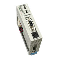
Panasonic fp2/fp2sh User Manual (374 pages)
programmable controller
Brand:
Panasonic
| Category:
Controller
| Size: 13.48 MB
Table of Contents
Table of Contents
3
Before You Start
9
Special Precautions
11
Compatibility with CPU Unit, and Precautions
14
Index
14
Compatibility of FP2SH and FP2, and Precautions
15
IC Memory Cards for the FP2SH
16
Compatibility of FP2/FP2SH and FP10SH, and Precautions
17
Programming Tool Restrictions
18
Chapter 1 Overview
19
System Configuration
21
Basic Configuration by Number of Slots
21
Expansion of Backplane
23
Unit Types and Combinations
26
Line-Up of Backplanes and Units
26
Combinations that Can be Used and Restrictions
28
Restrictions on Unit Types
28
Limitations on Current Consumption
30
Expansion Function
33
Computer Link
33
Connection of MODEM
35
Programming Tools
37
Tools Needed for Programming
37
Software Environment and Suitable Cable
38
Tools Needed for ROM Creating
39
Chapter 2 Parts and Functions
41
Backplane and Expansion Cable
43
Backplane
43
Basic Backplane H Type (FP2−BP**MH)
45
Expansion Backplane H Type (FP2−BP**EH)
46
Expansion Cable
47
Fp2 Cpu
48
Standard Type CPU (FP2−C1)
48
CPU with 64 Points Input (FP2−C1D)
52
Expansion Memory Unit and ROM (for FP2 CPU)
55
Fp2Sh Cpu
58
32K/60K Step Standard Type CPU (FP2-C2L/FP2-C2)
59
CPU with IC Memory Card Interface (FP2-C2P/FP2−C3P)
60
Expansion Memory Unit and ROM (for FP2−C2L/FP2-C2)
62
IC Memory Card (for FP2-C2P/FP2-C3P)
63
Power Supply Units
68
Power Supply Specifications
68
Input and Output Units
70
Common Specifications of Input and Output Units
70
Input Units Specifications
73
16-Point Type DC Input Unit
73
32-Point Type DC Input Unit
75
64-Point Type DC Input Unit
77
2.10 Output Units Specifications
79
16-Point Type Relay Output Unit
79
6-Point Type Relay Output Unit
81
16-Point Type Transistor (NPN) Output Unit
83
16-Point Type Transistor (PNP) Output Unit
85
32-Point Type Transistor (NPN) Output Unit
87
32-Point Type Transistor (PNP) Output Unit
89
64-Point Type Transistor (NPN) Output Unit
91
64-Point Type Transistor (PNP) Output Unit
93
2.11 I/O Mixed Units Specifications
95
32−Point Type DC Input/32−Point Type Transistor (NPN) Output Unit
95
32−Point Type DC Input/32−Point Type Transistor (PNP) Output Unit
98
32−Point Type DC Input with on Pulse Catch Input Function/ 32−Point Type Transistor Output (NPN) Unit
101
32−Point Type DC Input with on Pulse Catch Input Function/ 32−Point Type Transistor Output (PNP) Unit
104
On Pulse Catch Input Function
107
Chapter 3 I/O Allocation
109
Fundamentals of I/O Allocation
111
I/O Allocation and Registering
111
Precautions Regarding Registering of I/O Allocation
111
Types of I/O Allocation Methods
111
How to Count the I/O Numbers and Express the Occupied Points
112
Table of Occupied I/O Points by Unit
113
Arbitrary Allocation
115
Allocation Example of CPU Backplane
115
Using Arbitrary Allocation
115
Allocation Example of Expansion Backplane
118
When Using FP2 Backplane
118
When Using FP2 Backplane H Type
119
I/O Mount Allocation
121
Example of I/O Mount Allocation
121
Using I/O Mount Allocation
121
Procedure for I/O Mount Allocation
122
Automatic Allocation
123
Example of Automatic Allocation
123
Using Automatic Allocation
123
Procedure for Automatic Allocation
124
Procedure for Clearing Registered Content
125
Clearing Content Using Programming Tool Software
125
Meaning of Clearing Registered Content
125
I/O Numbers of Free Slots
126
Differences Due to Allocation Methods
126
When Arbitrary Allocation Is Used
126
When I/O Mount Allocation Is Used
128
When Automatic Allocation Is Used
129
Chapter 4 Installation and Wiring
131
Installation
133
Installation Space and Environment
133
Backplane
136
Mounting Method
136
Units
138
Connecting Expansion Cable
141
Preparing the Backup Battery
143
Power Supply Wiring
145
Wiring of Power Supply
145
Grounding
147
Wiring Input and Output
148
Input Wiring
148
Output Wiring
151
Cautions Regarding Units
152
Wiring the Connector Type I/O Units
153
Wiring the Connector Type Units
153
Connecting with Connector for Wire-Pressed Terminal Cable
155
Connecting the Terminals
157
Connecting with Flat Cable Connector
162
Wiring the Terminal Block Type I/O Units
164
Safety Measures
166
Safety Instructions
166
Alarm Output
167
Momentary Power Failures
167
Chapter 5 Procedure until Operation
169
Before Turning on the Power
171
Check Items
171
Procedure up to Operation
172
Programming with Programming Tool Software
173
Preparations
173
Configuration of Programming Tool Software
174
Parameters and Setting Methods
174
Chapter 6 FP2/FP2SH Operation
177
FP2 Operation
179
Comparison of RAM and ROM Operations
179
FP2 RAM and ROM Operations
179
Retaining the Data During Power Outages
180
Setting the Battery Error Warnings
180
FP2 RAM Operation
181
Precautions When Operating the RAM
181
RAM Operation Method
181
FP2 ROM Operation
182
ROM Operation Method
182
Verifying the ROM Contents in RAM Operation
183
Writing to ROM
184
Writing to EPROM Using Programming Tool Software
184
Writing to EPROM Via from
186
FP2SH Operation
189
Comparison of RAM, ROM, and IC Memory Card Operation
189
Retaining Data if the Power Fails
190
Comment Function
192
FP2SH RAM Operation
193
RAM Operation Method
193
Precautions When Operating the RAM
194
FP2SH ROM Operation
195
ROM Operation Function
195
ROM Operation Method
196
Precautions When Operating the ROM
197
Checking the ROM Contents While Using RAM Operation
198
Sending Data from the RAM to the from
199
Writing Data to the ROM (AFP5209) (Only the FP2−C2 Can be
201
Writing Data to the ROM: Using the FPWIN GR
203
FP2SH IC Memory Card Operation (for FP2−C2P/FP2−C3P)
205
Operating Using the IC Memory Card
205
Creating Files for Automatically Run Programs
207
How the IC Memory Card Is Operated
208
Transferring Data from the RAM to the IC Memory Card
209
Chapter 7 IC Memory Card
211
Using the IC Memory Card
213
Types of IC Memory Cards
213
Using the IC Memory Card
214
Formatting and Erasing
216
Program Memory Field and Expanded Memory Field
216
Procedure for Formatting the IC Memory Card
218
Procedure for Erasing the IC Memory Card
221
Data Storage Capacity of IC Memory Card
222
For Use as Program Memory
223
Writing the Program
223
Reading the Program
228
For Use as Expansion Memory
232
Menus Related to Tool Software
235
Chapter 8 Self-Diagnostic Function and Troubleshooting
237
Self-Diagnostic Function
239
LED Display for Status Condition
239
Operation When an Error Occurs
240
Troubleshooting
241
If the ALARM LED Lights
243
If the LED (POWER) of the Power Supply Unit Does Not Light
243
If Outputting Does Not Occur as Desired
244
If a Communication Error Message Appears
245
If a Protect Error Message Appears
246
Chapter 9 Maintenance
249
Replacement of Spare Parts
249
Removable Terminal Block for Input and Output Units
253
Preventive Maintenance
254
Chapter 10 Specifications
257
Specifications
257
(Typical Value)
259
Alarm Relays (E)
259
Expanded Construction
259
External Output (Y) Internal Relays (R)
259
Link Relays (L)
259
Pulse Relays (P)
259
Using Remote I/O System Program Capacity Internal Memory
259
3,072 Words
262
Using Backplanes H Type: Max. 512 Points (8 Modules)
262
Using Backplanes: Max. 1,600 Points
262
Relays, Memory Areas and Constants
264
Fp2−C2, Fp2−C2P, Fp2−C3P
265
Fp2−C2L
265
To 14,333 Words
265
Cable/Adapter Specifications
267
Chapter 11 Appendix
270
System Registers/Special Internal Relays/Special Data Registers
270
14,333 Words
272
Table of System Registers for FP2/FP2SH/FP10SH
272
Table of Special Internal Relays for FP2/FP2SH/FP10SH
286
Special Data Registers for FP2/FP2SH/FP10SH/FP3
297
Table of Basic Instructions
322
Table of High−Level Instructions
330
Table of Error Codes
350
Table of Syntax Check Error
352
Table of Self−Diagnostic Error
354
Table of MEWTOCOL−COM Communication Error
361
MEWTOCOL−COM Communication Commands
363
Hexadecimal/Binary/Bcd
364
ASCII Codes
365
Record of Changes
371
Advertisement
Advertisement
Related Products
Panasonic FP2-MW
Panasonic FP2 -C1A
Panasonic FP2 -AD8
Panasonic FP2 -DA4
Panasonic FP2-CAN-S
Panasonic FP2-ET1
Panasonic FP2-ET2
Panasonic FP2-PP2T
Panasonic FP2-PP4T
Panasonic FP2-PP4L
Panasonic Categories
Camcorder
Air Conditioner
TV
Digital Camera
Cordless Telephone
More Panasonic Manuals
Login
Sign In
OR
Sign in with Facebook
Sign in with Google
Upload manual
Upload from disk
Upload from URL