Sign In
Upload
Manuals
Brands
Omron Manuals
Controller
R88D-KN series
Omron R88D-KN series Manuals
Manuals and User Guides for Omron R88D-KN series. We have
3
Omron R88D-KN series manuals available for free PDF download: User Manual, Startup Manual
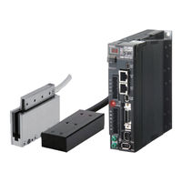
Omron R88D-KN series User Manual (629 pages)
EtherCAT COMMUNICATIONS Linear Motor Type
Brand:
Omron
| Category:
Servo Drives
| Size: 8 MB
Table of Contents
Introduction
3
Manual Configuration
4
Manual Structure
5
Sections in this Manual
7
Table of Contents
8
Contents
9
Terms and Conditions Agreement
14
Safety Precautions
16
Regulations and Standards
28
Items to Check after Unpacking
31
Revision History
34
Features and System Configuration
35
Outline
36
Features of G5-Series Servo Drives
36
What Is Ethercat
37
Object Dictionary
37
System Configuration
38
Names and Functions
40
Servo Drive Part Names
40
Servo Drive Functions
41
System Block Diagram
42
Unit Versions
46
Confirmation Method
46
Models and External Dimensions
47
Servo System Configuration
48
How to Read Model Numbers
50
Servo Drive
50
Linear Motor
51
Model Tables
53
Servo Drive Model Table
53
Linear Motor Model Table
53
Servo Drive and Linear Motor Combination Tables
54
Cable and Peripheral Device Model Tables
56
External and Mounting Dimensions
58
Servo Drive Dimensions
58
Linear Motor Dimensions
66
External Regeneration Resistor Dimensions
73
Reactor Dimensions
74
Mounting Bracket Dimensions
77
Specifications
79
Servo Drive Specifications
80
General Specifications
80
Characteristics
81
Ethercat Communications Specifications
83
Ethercat Communications Connector Specifications (RJ45)
83
Control I/O Specifications (CN1)
84
Control Input Circuits
86
Control Input Details
87
Control Output Circuits
89
Control Output Details
90
External Encoder Specifications
94
External Encoder Connector Specifications (CN4)
95
Analog Monitor Connector Specifications (CN5)
99
USB Connector Specifications (CN7)
100
Safety Connector Specifications (CN8)
100
Overload Characteristics (Electronic Thermal Function)
103
Linear Motor Specifications
106
General Specifications of Iron-Core Linear Motors
106
Performance Specifications of Iron-Core Linear Motors
107
Iron-Core Linear Motor Speed - Force Characteristics
110
Temperature Sensor Specifications of Iron-Core Linear Motors
113
General Specifications of Ironless Linear Motors
114
Performance Specifications of Ironless Linear Motors
114
Ironless Linear Motor Speed - Force Characteristics
117
Temperature Sensor Specifications of Ironless Linear Motors
122
Cable Specifications
123
Cable and Connector Specifications
124
Resistance to Bending of Robot Cable
124
External Encoder Cable Specifications
125
Connector Specifications
126
Ethercat Communications Cable Specifications
127
Analog Monitor Cable Specifications
130
Control Cable Specifications
131
External Regeneration Resistor Specifications
136
Reactor Specifications
137
System Design
139
Installation Conditions
140
Iron-Core Linear Motor Installation Conditions
142
Ironless Linear Motor Installation Conditions
148
Wiring
152
Peripheral Equipment Connection Examples
152
Main Circuit and Linear Motor Connections
156
Terminal Block Wire Sizes
160
Terminal Block Wiring Procedure
162
Wiring Conforming to EMC Directives
164
100-VAC and 200-VAC Input Servo Drive Models
164
400-VAC Input Servo Drive Models
165
Conformity to IEC 61800-5-1
167
Noise Reduction
169
Wiring Method
169
Selecting Connection Components
173
Regenerative Energy Absorption
187
Calculating the Regenerative Energy
187
Servo Drive Regeneration Absorption Capacity
189
Regenerative Energy Absorption with an External Regeneration Resistor
190
Connecting an External Regeneration Resistor
191
Ethercat Communications
195
Display Area and Settings
196
Node Address Setting
196
Status Indicators
197
Structure of the CAN Application Protocol over Ethercat
198
Ethercat State Machine
199
Process Data Objects (Pdos)
200
PDO Mapping Settings
200
Sync Manager PDO Assignment Settings
201
Fixed PDO Mapping
201
Variable PDO Mapping
203
Multiple PDO Mapping
204
Service Data Objects (Sdos)
206
Synchronization with Distributed Clocks
207
Emergency Messages
208
Sysmac Device Features
209
Basic Control Functions
213
Cyclic Synchronous Position Mode
214
Related Objects
215
Block Diagram for Position Control Mode
216
Cyclic Synchronous Velocity Mode
217
Related Objects
218
Objects Requiring Settings
218
Related Functions
218
Block Diagram for Speed Control Mode
219
Cyclic Synchronous Torque Mode
220
Related Functions
222
Block Diagram for Force Control Mode
222
Profile Position Mode
223
Related Objects
224
Description of Function
225
Controlword (6040 Hex) in Profile Position Mode
226
Statusword (6041 Hex) in Profile Position Mode
226
Homing Mode
227
Connecting with OMRON Controllers
228
Applied Functions
231
Output Signals
235
Positive and Negative Drive Prohibition Functions
238
Overrun Protection
241
Operating Conditions
241
Objects Requiring Settings
241
Operation Example
242
Backlash Compensation
243
Brake Interlock
245
Objects Requiring Settings
245
Operation Timing
246
Electronic Gear Function
250
Objects Requiring Settings
250
Operation Example
251
Force Limit Switching
252
Operating Conditions
252
Objects Requiring Settings
252
Soft Start
254
Objects Requiring Settings
254
Soft Start Acceleration or Deceleration Time
254
S-Curve Acceleration or Deceleration Time
255
Gain Switching Function
256
Objects Requiring Settings
256
Gain Switching Based on the Control Mode
258
Diagrams of Gain Switching Setting
261
Position Gain Switching Time (3119 Hex)
266
Safety Function
273
Safe Torque off Function
274
Safety Input Signals
275
External Device Monitor (EDM) Output Signal
276
Relationship between Safety Input Signals and EDM Output Signal
276
Operation Example
277
Connection Example
279
Servo Parameter Objects
281
Basic Settings
282
Gain Settings
287
Vibration Suppression Settings
298
Analog Control Objects
305
Interface Monitor Settings
310
Extended Objects
321
Special Objects
327
Linear Motor Objects
341
Operation
352
Operational Procedure
352
Preparing for Operation
354
Items to Check before Turning on the Power Supply
354
Turning on the Power Supply
356
Checking the Displays
356
Preparing the Linear Motor for Operation
358
Linear Motor Setup
363
Outline of Linear Motor Setup
364
Operation from the CX-Drive
364
Connection from the CX-Drive Via Network
373
Connection from the Sysmac Studio Via Network
375
Trial Operation
377
Preparations for Trial Operation
377
Trial Operation Via USB Communications from the CX-Drive
378
Setup Via Network
378
Adjustment Functions
379
Gain Adjustment
383
Purpose of the Gain Adjustment
383
Gain Adjustment Methods
383
Gain Adjustment Procedure
384
Realtime Autotuning
385
Operating Conditions
386
Objects Requiring Settings
386
Setting Realtime Autotuning
387
Setting Machine Rigidity
388
Objects to be Updated
390
Manual Tuning
393
Preparation for Manual Tuning
393
Position Control Mode Adjustment
394
Damping Control
395
Operating Conditions
395
Objects Requiring Settings
396
Operating Procedure
397
Adaptive Filter
399
Operating Conditions
400
Objects Requiring Settings
400
Objects to be Set Automatically
401
Operating Procedure
401
Notch Filters
402
Objects Requiring Settings
403
Notch Filter Width and Depth
404
Disturbance Observer Function
406
Operating Conditions
406
Objects Requiring Settings
407
Operating Procedure
407
Friction Force Compensation Function
408
Operating Conditions
408
Objects Requiring Settings
408
Operating Procedure
409
11-10Feed-Forward Function
410
Objects Requiring Settings
410
Operating Procedure
411
11-11Instantaneous Speed Observer Function
413
Operating Conditions
413
Objects Requiring Settings
414
Operating Procedure
414
Actions for Problems
416
Preliminary Checks When a Problem Occurs
416
Precautions When a Problem Occurs
417
Replacing the Linear Motor or Servo Drive
417
Warnings
419
Related Objects
419
Warning List
420
Errors
423
Error List
423
Immediate Stop Operation at Errors
425
Troubleshooting
427
Troubleshooting with Error Displays
427
Troubleshooting with the al Status Code
441
Troubleshooting Using the Operation State
442
Periodic Maintenance
449
Linear Slider Life Expectancy
449
Servo Drive Life Expectancy
450
Appendices
451
Cia402 Drive Profile
452
Controlling the State Machine of the Servo Drive
452
A-1-2 Modes of Operation
454
A-1-3 Communications Cycles and Corresponding Modes of Operation
455
A-1-4 Modes of Operation and Applied Functions
456
A-1-5 Changing the Mode of Operation
457
A-1-6 Homing Mode Specifications
465
Communication Objects
475
PDO Mapping Objects
481
Sync Manager Communication Objects
494
A-1-11 Manufacturer Specific Objects
499
A-1-12 Servo Drive Profile Objects
505
Object List
527
Sysmac Error Status Codes
545
A-3-1 Error Table
545
A-3-2 Error Description
559
Response Time in Ethercat Process Data Communications
617
A-4-1 Input Response Time
617
A-4-2 Output Response Time
618
Ethercat Terminology
619
Advertisement
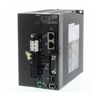
Omron R88D-KN series User Manual (570 pages)
G5-series WITH BUILT-IN EtherCAT COMMUNICATIONS Linear Motor Type
Brand:
Omron
| Category:
Controller
| Size: 34 MB
Table of Contents
Introduction
3
Structure of this Document
4
Manual Structure
5
Sections in this Manual
7
Table of Contents
8
Contents
9
Read and Understand this Manual
14
Safety Precautions
17
Regulations and Standards
24
Items to Check after Unpacking
26
Revision History
27
Features and System Configuration
29
Outline
30
Features of G5-Series Servo Drives
30
What Is Ethercat
31
Object Dictionary
31
System Configuration
32
Names and Functions
33
Servo Drive Part Names
33
Servo Drive Functions
34
System Block Diagram
35
Models and External Dimensions
45
Section 2 Models and External Dimensions
46
Servo System Configuration
46
How to Read Model Numbers
48
Servo Drive
48
Model Tables
49
Servo Drive Model Table
49
Cable and Peripheral Device Model Tables
50
External and Mounting Dimensions
52
Servo Drive Dimensions
52
External Regeneration Resistor Dimensions
68
Reactor Dimensions
69
Mounting Bracket Dimensions
73
Specifications
75
Section 3 Specifications
76
Servo Drive Specifications
76
General Specifications
76
Characteristics
76
Ethercat Communications Specifications
79
Ethercat Communications Connector Specifications (RJ45)
79
Control I/O Specifications (CN1)
80
Control Input Circuits
83
Control Input Details
83
Control Output Circuits
85
Control Output Details
86
External Encoder Specifications
90
External Encoder Connector Specifications (CN4)
91
Analog Monitor Connector Specifications (CN5)
95
USB Connector Specifications (CN7)
96
Safety Connector Specifications (CN8)
97
Overload Characteristics (Electronic Thermal Function)
99
Cable and Connector Specifications
101
Bend Radius of Robot Cable
101
Connector Specifications
102
Ethercat Communications Cable Specifications
103
Analog Monitor Cable Specifications
106
Control Cable Specifications
107
External Regeneration Resistor Specifications
112
Reactor Specifications
113
System Design
115
Installation Conditions
116
Wiring
118
Peripheral Equipment Connection Examples
118
Main Circuit and Linear Motor Connections
128
Terminal Block Wire Sizes
138
Terminal Block Wiring Procedure
143
Wiring Conforming to EMC Directives
145
Wiring Method
145
Selecting Connection Component
153
Regenerative Energy Absorption
165
Calculating the Regenerative Energy
165
Servo Drive Regeneration Absorption Capacity
167
Regenerative Energy Absorption with an External Regeneration Resistor
168
Connecting an External Regeneration Resistor
169
Ethercat Communications
173
Display Area and Settings
174
Node Address Setting
174
Status Indicators
175
Structure of the CAN Application Protocol over Ethercat
176
Structure of the CAN Application Protocol
176
Ethercat State Machine
177
Process Data Objects (Pdos)
178
PDO Mapping Settings
178
Sync Manager PDO Assignment Settings
179
Fixed PDO Mapping
179
Variable PDO Mapping
181
Multiple PDO Mapping
182
Service Data Objects (Sdos)
184
Synchronization with Distributed Clocks
185
Emergency Messages
186
Sysmac Device Features
187
Basic Control Functions
191
Section 6 Basic Control Functions
192
Cyclic Synchronous Position Mode
192
Block Diagram for Position Control Mode
194
Cyclic Synchronous Velocity Mode
195
Block Diagram for Speed Control Mode
197
Cyclic Synchronous Torque Mode
198
Block Diagram for Force Control Mode
200
Profile Position Mode
201
Related Objects
202
Description of Function
203
Controlword (6040 Hex) in Profile Position Mode
204
Statusword (6041 Hex) in Profile Position Mode
204
Homing Mode
205
Connecting with OMRON Controllers
206
Applied Functions
209
Section 7 Applied Functions
210
Sequence I/O Signals
210
Output Signals
213
Positive and Negative Drive Prohibition Functions
216
Overrun Protection
219
Operating Conditions
219
Objects Requiring Settings
221
Backlash Compensation
221
Brake Interlock
223
Objects Requiring Settings
223
Operation Timing
224
Electronic Gear Function
228
Objects Requiring Settings
228
Operation Example
229
Force Limit Switching
230
Operating Conditions
230
Objects Requiring Settings
231
Soft Start
233
Objects Requiring Settings
233
Soft Start Acceleration or Deceleration Time
233
S-Curve Acceleration or Deceleration Time
234
Gain Switching Function
235
Objects Requiring Settings
235
Gain Switching Based on the Control Mode
237
Diagrams of Gain Switching Setting
240
Position Gain Switching Time (3119 Hex)
244
Gain Switching 3 Function
245
Operating Conditions
245
Objects Requiring Settings
245
Operation Example
245
Touch Probe Function (Latch Function)
247
Operation Sequences
248
Safe Torque off Function
252
Safety Input Signals
253
External Device Monitor (EDM) Output Signal
254
Relationship between Safety Input Signals and EDM Output Signal
254
Operation Example
255
Connection Examples
257
Servo Parameter Objects
259
Basic Settings
260
Gain Settings
265
Vibration Suppression Settings
275
Analog Control Objects
281
Interface Monitor Settings
285
Extended Objects
295
Special Objects
301
Linear Motor Objects
314
Operation
323
Operational Procedure
324
Preparing for Operation
325
Items to Check before Turning on the Power Supply
325
Turning on the Power Supply
326
Checking the Displays
327
Preparing the Linear Motor for Operation
329
Trial Operation
334
Preparations for Trial Operation
334
Test Operation Via USB Communications from the CX-Drive
335
Adjustment Functions
337
Analog Monitor
338
Gain Adjustment
341
Purpose of the Gain Adjustment
341
Gain Adjustment Methods
341
Gain Adjustment Procedure
342
Realtime Autotuning
343
Operationg Conditions
343
Objects Requiring Settings
344
Setting Realtime Autotuning
345
Setting Machine Rigidity
345
Objects to be Changed
348
Manual Tuning
350
Preparation for Manual Tuning
350
Damping Control
352
Operating Conditions
352
Objects Requiring Settings
353
Operating Procedure
354
Adaptive Filter
356
Operating Conditions
357
Objects Requiring Settings
357
Objects to be Set Automatically
358
Operating Procedure
358
Notch Filters
359
Objects Requiring Settings
360
Notch Filter Width and Depth
360
Disturbance Observer Function
362
Operating Conditions
362
Objects Requiring Settings
363
Operating Procedure
363
Friction Force Compensation Function
364
Operating Conditions
364
Objects Requiring Settings
364
Operation Example
365
Feed-Forward Function
366
Objects Requiring Settings
366
Operating Procedure
367
11-11Instantaneous Speed Observer Function
369
Operating Conditions
369
Instantaneous Speed Observer Function
369
Objects Requiring Settings
370
Operating Procedure
370
Troubleshooting and Maintenance
371
Actions for Problems
372
Preliminary Checks When a Problem Occurs
372
Precautions When a Problem Occurs
373
Replacing the Servo Drive
373
Warnings
374
Related Objects
374
Warning List
375
Errors
377
Error List
377
Immediate Stop Operation at Errors
379
Troubleshooting
381
Troubleshooting with Error Displays
381
Troubleshooting Using the Operation State
392
Periodic Maintenance
398
Appendicies
401
A-1 Cia402 Drive Profile
401
Controlling the State Machine of the Servo Drive
402
Modes of Operation
404
A-1-3 Communications Cycles and Corresponding Modes of Operation
405
Modes of Operation
405
A-1-4 Modes of Operation and Applied Functions
406
A-1-5 Changing the Mode of Operation
407
A-1-6 Homing Mode Specifications
415
Object Dictionary
422
A-1-6 Homing Mode Specifications
423
A-1-8 Communication Objects
424
PDO Mapping Objects
430
Sync Manager Communication Objects
443
A-1-11 Manufacturer Specific Objects
448
A-1-12 Servo Drive Profile Object
454
Object List
475
Sysmac Error Status Codes
493
A-3-1 Error Table
493
A-3-2 Error Description
505
Ethercat Terminology
559
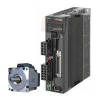
Omron R88D-KN series Startup Manual (47 pages)
Programmable Multi-Axis Controller, Servo Drivers, IDEv4
Brand:
Omron
| Category:
Servo Drives
| Size: 1 MB
Table of Contents
Table of Contents
3
1 Related Manuals
4
2 Terms and Definitions
5
3 Precautions
6
4 Overview
7
5 Applicable Devices and Device Configuration
8
Applicable Devices
8
Device Configuration
9
6 Ethercat Connection Procedure
10
Workflow
10
Preparation for the Controller Setup
12
Installation of ESI Files
17
Ethercat Communications Setup
17
Controller Settings
25
7 Appendix Saving and Loading a Project
36
Saving a Project
36
Loading and Downloading a Project
38
8 Appendix Troubleshooting
41
Factors Causing Ethercat Communications to be Unavailable, and Corrective Actions
41
How to Check for Errors
42
9 Appendix Ecat[I] Structure Elements
45
10 Revision History
46
Advertisement
Advertisement
Related Products
Omron R88D-KN*-ECT Series
Omron R88D-KNA5L-ML2
Omron R88D-KN01L-ML2
Omron R88D-KN02L-ML2
Omron R88D-KN04L-ML2
Omron R88D-KN20H-ML2
Omron R88D-KN30H-ML2
Omron R88D-KN50H-ML2
Omron R88D-1SN150F-ECT
Omron R88D-1SAN20F-ECT
Omron Categories
Blood Pressure Monitor
Controller
Accessories
Switch
Inverter
More Omron Manuals
Login
Sign In
OR
Sign in with Facebook
Sign in with Google
Upload manual
Upload from disk
Upload from URL