Sign In
Upload
Manuals
Brands
Nortel Manuals
Gateway
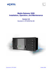
Media Gateway 3500
Nortel Media Gateway 3500 Manuals
Manuals and User Guides for Nortel Media Gateway 3500. We have
1
Nortel Media Gateway 3500 manual available for free PDF download: Installation, Operation And Maintenance Manual
Nortel Media Gateway 3500 Installation, Operation And Maintenance Manual (236 pages)
Brand:
Nortel
| Category:
Gateway
| Size: 4 MB
Table of Contents
Table of Contents
3
Introductory Matter
13
Introduction to the Media Gateway 3500
15
Gateway Block Diagram
15
Figure 1-1: Media Gateway Block Diagram
16
Hardware Overview
17
Media Gateway 3500 Hardware Configuration
17
Media Gateway 3500 + TP-1610 Board Configuration
17
Table 2-1: Components of the Media Gateway 3500 + TP-1610 Board Configuration
17
Media Gateway 3500 Accessories Kit
18
Front and Back Views of the Media Gateway 3500
18
Figure 2-1: Media Gateway 3500 + 1610 Configuration - Front View
18
The Chassis
19
Figure 2-2: Media Gateway 3500 + 1610 Configuration, DC Power - Back View
19
Figure 2-3: Media Gateway 3500 + 1610 Configuration, AC Power - Back View
19
Earthing Requirements
20
Power Requirements
20
Table 2-2: Chassis Dimensions
20
Table 2-3: Power Requirements
20
Power Consumption
21
Electro Magnetic Compatibility (EMC) Features
22
Midplane Keying
22
Cooling System
22
Fan Tray Unit
22
Advanced Power Module (APM)
23
Alarm Indicators
23
Figure 2-4: Fan Tray Unit Panel and Alarm Indicators
23
Alarm Indicators
24
Table 2-4: Chassis Front Panel Alarm Indicators and Buttons
24
Media Gateway 3500 Boards
25
The TP-1610 Board
25
Figure 2-5: 1610 Board, Panel View
26
Figure 2-6: 1610 RTM Panel with 2 Telco Connectors
27
50-Pin Telco Connector E1/T1/J1 Connections
29
Figure 2-7: 50-Pin Female Telco Board-Mounted Connector
29
Table 2-5: E1/T1/J1 Connections on each 50-Pin Telco Connector
29
TP-1610 Board Panel LED Indicators
30
Table 2-6: Board Status LED Indicators
30
Table 2-7: Trunks Status LED Indicators
30
Table 2-8: Cpci Indicators
30
SC (System Controller) Board
31
Table 2-9: Ethernet Indicators
31
Front Panel PS2 COM Serial Port
32
Figure 2-8: SC Panel
32
Figure 2-9: SC Front Panel Serial Port Connector
33
Table 2-10: RS-232 Console Pin Signal Interface
33
System Controller Panel Indicators & Controls
34
SA Synchronization and Alarm RTM
34
Table 2-11: SC Board Indicators
34
Table 2-12: RS-232 Console Pin Signal Interface
35
Table 2-13: SA RTM LED Indicators
36
Figure 2-10: SA RTM Panel
37
Ethernet Switch Boards
38
Table 2-14: RJ-11 Console Port Pinout
39
4411 Panel Indicators
40
Figure 2-11: ES/4411 Panel
40
Table 2-15: Port/Link Activity Indicators
41
Table 2-16: Port Speed Indicators
41
Table 2-17: System Indicator
41
Table 2-18: Fault Indicator
41
4411 Physical Slots to Ethernet Port Correlation - Media Gateway 3500 + TP-1610 Configuration
42
Table 2-19: Ethernet Switch Hot-Swap Indicator
42
Table 2-20: ES/4411 Physical Slots to Ethernet Port Correlation
42
4411 Rtm
43
Table 2-21: ES/4411 RTM Port Pinouts
43
Figure 2-12: ES/4411 RTM Panel
44
Figure 2-13: ES/4411 RTM F-Link Location
45
Table 2-22: ES/4411 RTM F-Link Settings
45
Installation Process Flow
47
Installation Process Flow (TP-1610 Configuration)
47
Figure 3-1: Installation Process Flow (TP-1610 Configuration)
48
Site Preparation
49
Physical Requirements
49
Equipment
49
Table 4-1: Equipment Requirements
49
Electrical
50
Table 4-2: Electrical Requirements
50
Cables
51
Table 4-3: Cabling Requirements
51
Defining IP Parameters
52
Gateway Addresses
52
Table 4-4: Gateway Addresses
52
Network Server IP Addresses
53
Table 4-5: Network Server IP Addresses
53
Diffserv Priorities
54
IEEE 802.1P Qos/Cos Layer 2 Traffic Prioritization
54
Table 4-6: Diffserv Priority Parameters
54
Table 4-7: IEEE 802.1P Service Proirity Classes
54
Security Profiles
55
Defining IP Parameters - Media Gateway 3500 + TP-1610
55
Configuration
55
Table 4-8: Security Profiles
55
Table 4-9: MAC Address and IP Address Registration for Media Gateway 3500 + TP-1610
55
Environmental Requirements
56
Nebs Environmental Requirements
56
Table 4-10: NEBS Requirements
56
Temperature
57
Humidity
57
Lightning Protection
57
Altitude
57
Earthquake
57
Table 4-11: Temperature Range
57
Table 4-12: Humidity Range
57
Table 4-13: Altitude Range
57
Table 4-14: Earthquake Requirements
57
Rack Requirements
58
Interfacing with the IP Networks
58
Method One: Cluster of Two Interconnected L-2 Switches
58
Figure 4-1: Clustering of Two L-2 Switches
58
Table 4-15: Rack Requirements
58
Method Two: One L-2 Switch with Two Vlans
59
Figure 4-2: Multiple IP Networks
59
Clock Synchronization
60
Clock Synchronization for PSTN Interfaces
60
Connections for the Non Synchronized Mode
60
Connections for the Synchronized Mode
61
Figure 4-3: Non-Synchronized Mode Connections Diagram
61
Figure 4-4: Synchronized Mode Connections Diagram
62
Unpacking/Checking Contents
65
Mounting the Chassis on a Rack
67
Figure 6-1: Attaching the Chassis to the Rack
68
Figure 6-2: Chassis on the Rack - Front View
69
Figure 6-3: Installing Rack Using Pre-Installed Support Studs
69
Earthing
71
Earthing the Gateway
71
Figure 7-1: Earthing Connections Chassis Rear Pems (DC Version)
71
Figure 7-2: Earthing Connections Chassis Rear PEM (AC Version)
72
Powering up
73
Pre-Power Connection Test Procedures Checklist
73
Connecting System Power
74
Figure 8-1: PS-2 Power Supply
74
Table 8-1: Power Requirements
74
Connecting AC Power
75
Table 8-2: AC Power Cable Types
75
Connecting DC Power
76
Figure 8-2: DC Power Connections Redundant Pairs
77
Figure 8-3: Making the DC Power Connections
78
Post-Power Connection Test Procedures Checklist
79
Table 8-3: Functional Checks on Component Indicators
79
Configuring SC Software for the First Time
83
Console Terminal Cabling
83
Defining IP Parameters
84
Configuring the NTP Server
84
Connecting Via an RS-232 Terminal
84
Configuring the SC Boards
85
Updating the Basic SC Network Configuration
86
Performing the Basic SC Configuration
87
Basic SC Configuration on the First SC Board
88
Basic SC Configuration on the Second SC Board
93
Software Testing
95
SC Software Backup/Restore Procedures
97
Creating the SC Software Backup
97
Restoring SC Software from Backup
98
Cabling the Media Gateway 3500
101
Connecting the ES/4411 IP Network Cabling
101
Table 11-1: IP Separation and Es/4411S Port Allotment
102
TP-1610 Configuration - Cabling the Trunk Connectors
103
External Alarm Indicator Connections
103
Figure 11-1: Normal Logic Alarm Connection Diagram
104
Figure 11-2: Inverse Logic Alarm Connection Diagram
104
Operating the Media Gateway Using the EMS
105
Figure 12-1: EMS Regions Screen
106
Figure 12-2: EMS - Main Screen, Media Gateway Displayed
107
EMS Architecture Overview
108
Figure 12-3: Trunk Parameters Provisioning Screen
108
Basic Media Gateway Configuration in the EMS
109
Figure 12-4: Media Gateway Management System Architecture
109
Performance Monitoring
110
Real-Time Performance Monitoring
111
Figure 12-5: Display Real Time Pms
111
Figure 12-6: Selecting the Frame to Display the Graph of the Entity Performance
111
Viewing Historical Data
112
Operating a Redundant Gateway
112
Media Gateway Board Redundancy
113
Ethernet Switch Boards Redundancy
113
SC Redundancy
114
Clock Control Application
114
Technical Overview
114
Figure 12-7: EMS Media Gateway Status Screen Showing Popup Menu
114
Configuring Clock Control
115
NONE' Working Mode (Unsynchronized Mode)
115
SYNCHRONIZED' Working Mode
115
Clock Synchronization Configuration Limitations for TP-1610 Configurations
117
SYNC Mode
117
NONE (Synchronized) Mode
117
Configuring the IP Addresses
118
Media Gateway IP Addresses
118
Figure 12-8: Subnet Separation Screen
118
Figure 12-9: Static Route Table Screen
119
Auxiliary Files
120
Call Progress Tone and User-Defined Tone Auxiliary Files
120
Format of the Call Progress Tones Section in the Auxiliary Source File
121
Format of the User Defined Tones Section
123
Default Template for Call Progress Tones
124
Table 12-1: Default Call Progress Tones
124
Modifying the Call Progress Tones File
126
Converting a Modified CPT Ini File to a Dat File with the Download Conversion Utility
128
Playing Prerecorded Tones (PRT)
128
PRT File Configuration
128
Downloading the PRT Dat File
128
Setting Diffserv Priorities
130
Figure 12-10: Diffserv Priorities Screen
130
Table 12-2: Diffserv Class Name and Protocol Group Assignments
131
Media Gateway 3500 Security Technology
133
Introduction to Ipsec and IKE
133
Ike
133
Ipsec
133
Media (RTP/RTCP) Security
133
Ssh
134
Ssl/Tls
134
Media Gateway 3500 Security Configuration
134
Enable Secure Mode
134
Software Re-Installation
135
Enable Secure Mode Examples
135
Disable Secure Mode
137
Software Re-Installation
137
Disable Secure Mode Examples
137
Testing the Installed System
139
Hardware Replacement Procedures
141
Board Replacement Preliminaries
141
ESD Requirements
141
Slot Cover Requirements
141
SC Board Replacement Procedure
142
Figure 14-1: Blank Panel for Front Slots
142
Figure 14-2: Blank Panel for Rear Slots
142
Figure 14-3: Red Ejector Buttons on a Board
143
Installing the Solaris™ 9 os
144
Installation Requirements
144
Preparing the 'Install Image
145
Installing the Solaris™ 9 os on the SC Board
145
Installing the SC Software
146
SC Installation Package
147
Copying the SC Software
147
Table 14-1: SC Installation Package Files
147
Redundant Configuration - Installing the SC Software
148
Media Gateway Board Replacement Procedure
153
Media Gateway Board Definition Methods
153
Ascertaining the MAC Addresses for the TP-1610
156
Figure 14-4: TP-1610 Board MAC Address Locations
156
Figure 14-5: MAC Address Locations on TP-1610 Board
156
SA RTM Replacement Procedure
157
Ethernet Switch Board Replacement Procedure
157
Power Supply Module Replacement
159
Replacing the Fan Tray Unit
160
Replacing Air Filters
161
Figure 14-6: Air Filter
161
Software Upgrade
163
Online Software Upgrade - Overview
163
Pre-Upgrade Configuration Backup
163
Site Preparation
164
Preparing the Installation Server
164
TM os Image
165
FTP Server
165
Changing Network Configuration of Installation Server
166
Preparing the Ethernet Switch Boards
167
Preparing the Media Gateway Boards
167
Preparing the SC Boards
167
Preparing the Network
167
Performing the Online Software Upgrade
168
Configure Telnet/Ftp Password of the Media Gateway
169
Starting the Online Software Upgrade Wizard
169
Figure 15-1: Maintenance Actions Icon and Popup Menu
170
Figure 15-2: Files Management Screen
170
Welcome Questionnaire
172
Figure 15-3: Welcome to the Online Software Upgrade Wizard
172
Upgrading the Secondary SC Board
173
OS Upgrade Phase for Version 2.1 to Version 3.0 Upgrade
173
Figure 15-4: Software Upgrade in Process, Managed by the SC Board
173
Figure 15-5: Software Upgrade in Process, Includes Solaris
174
Figure 15-6: Software Upgrade in Process, Provisioning Parameter Values Screen
175
Manual os Upgrade
176
Figure 15-7: Software Upgrade in Process, os Upgrade Options Screen
176
Upgrading the Media Gateway Boards
177
Upgrading the Ethernet Switch Boards
177
Upgrading the Primary SC Board
178
Figure 15-8: Software Upgrade in Process, Verify F-Link Screen
178
SC Board Cleanup
179
Finish
179
Rollback
179
OS Downgrade
180
Figure 15-9: Software Upgrade in Process, Abort Screen
180
Ethernet Switch Board Downgrade in Version 2.1
181
Software Upgrade/Rollback Troubleshooting
182
Performing a Manual Rollback to the Previous Software Configuration182
182
Alternative to Rollback after "Secondary SC Upgrade" Phase During Version 2.1 to Version 3.0 Upgrade
185
Online Software Upgrade Wizard on a Simplex Configuration
185
Upgrade from Version 2.1 to Version 3.0 - Disabled New Features185
185
Upgrade from Version 2.1 to Version 3.0 - Known Limitations
186
Online Software Upgrade - Network Cleanup
186
Table 15-1: Disabled Features for Upgrade from Version 2.1 to Version 3.0
186
Shutdown Procedures
187
Diagnostics & Troubleshooting
189
Troubleshooting Strategy
189
Troubleshooting
190
Table 17-1: Troubleshooting Faults in the Media Gateway
190
Syslog Support
195
Gateway Faults and Alarm Monitoring
195
List of Alarms
196
Application, Solaris™ Log Files' Directories
197
Simple Diagnostic Tool's File
197
Useful Solaris™ Configuration Files
197
Table 17-2: Useful Solaris™ Configuration Files
197
Simple Diagnostic Tool's File
198
Useful Solaris™ Configuration Files
198
Information Needed When Contacting Technical Support
198
Table 17-3: Useful Solaris™ Configuration Files
198
Media Gateway 3500 Selected Functional Specifications
201
Table 18-1: Media Gateway 3500 Functional Specifications
201
Regulatory Information
207
Appendix - Installing es Board Software
211
Media Gateway 3500 Media Gateway Version 2.1
211
Troubleshooting
212
Appendix - Solaris
213
TM 8 os Installation
213
Introduction
213
Installation Requirements
213
Preparing the 'Install Image
213
Installing the SC Board
214
Installing the Solaris™ 8 os on the SC Board
214
Appendix - Updating the Media Gateway Boards Feature Key
217
Figure 22-1: Online Software Upgrade Wizard Screen - Update Feature Key Notice
217
Appendix - Getting Started with Mibs
219
MIBS and Provisioning Options
219
Configuring a Newly Inserted Media Gateway Board
220
Modifying a Media Gateway Board Configuration
221
Modifying a Trunk Configuration
221
Removing a Media Gateway Board
222
Appendix - Utilities
224
Downloadable Conversion Utility
224
Figure 24-1: Downloadable Conversion Utility Opening Screen
224
Process Call Progress Tones File(S)
225
Converting a CPT Ini File to a Binary Dat File
225
Figure 24-2: Call Progress Tones Screen
225
Process Voice Prompts File(S)
226
Figure 24-3: Voice Prompts Screen
226
Figure 24-4: Select Files Window
227
Figure 24-5: File Data Window
228
Packet Tracing
229
Trunk (PSTN) Traces
229
DSP Traces
230
Figure 24-6: Trunk Traces Screen
230
Figure 24-7: Udp2File Utility Dialog Box
230
Figure 24-8 Packet Recording Screen
232
Index
233
Advertisement
Advertisement
Related Products
Nortel 3100 Series
Nortel 3070
Nortel 3510-24T
Nortel BayStack 350 Series
Nortel BayStack 350F
Nortel BayStack 350T
Nortel BayStack 350F-HD
Nortel Networks BayStack 350T-HD
Nortel Media Dependent Adapters 302403-G
Nortel 3456
Nortel Categories
IP Phone
Telephone
Switch
Software
Server
More Nortel Manuals
Login
Sign In
OR
Sign in with Facebook
Sign in with Google
Upload manual
Upload from disk
Upload from URL