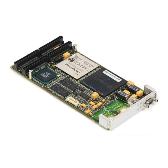
Sign In
Upload
Manuals
Brands
Motorola Manuals
Desktop
PPC/PMC-8260/DS1
Motorola PPC/PMC-8260/DS1 Manuals
Manuals and User Guides for Motorola PPC/PMC-8260/DS1. We have
1
Motorola PPC/PMC-8260/DS1 manual available for free PDF download: Reference Manual
Motorola PPC/PMC-8260/DS1 Reference Manual (150 pages)
Brand:
Motorola
| Category:
Desktop
| Size: 1.51 MB
Table of Contents
Table of Contents
3
Using this Guide
13
Revision History
18
Features
19
Features
20
Variants
20
Other Sources of Information
21
Safety Notes
23
Function Blocks
34
Restrictions
35
Variant Features
36
Standard Compliances
37
Ordering Information
38
2 Installation
41
Action Plan
41
Environmental Requirements
42
Power Requirements
43
Environmental Requirements of the PPC/PMC-8260/DS1
44
Current and Power Requirements
44
Location of Switch
45
Switch Settings
45
Allowed Product Combinations
46
Installing a PMC Module
48
Installation Procedure
49
Figure 3 Installation (Example with Powercorecpci-6750 Rev. 2.X)
50
Removal Procedure
51
Software Upgrades and Accessories
52
Front Panels
55
Indicators and Connectors
56
Front Panel Serial I/O Port Connector Pinout
56
Front Panel
57
Front Panel RJ-45 Interface Connector Pinout
57
Line Interface Connector
57
PMC I/O and Jtag/Debug Connector
59
On-Board Connectors
59
Figure 8 PMC I/O Connector Pinout for PMC-8260/DS1-SC-F
60
Figure 9
61
Figure 10 Jtag/Debug Connector
62
Figure 11 Jtag/Debug Connector Pinout
63
4 Firmware
67
Introduction
67
Power-Up Sequence
68
Figure 12 Flowchart of the PPC/PMC-8260/DS1 Firmware Power-Up Sequence
69
Table 10 Steps Performed During Power-Up
70
Loading Application Software
72
Preparing a ROM Image
73
Table 11 ROM Image Configuration Section
74
Argument Passed to ROM Image
75
System State at ROM Image Execution
76
Table 12 PCR Register Settings
77
Controlling Boot Process
77
Monitoring Boot Process
78
Primary Booter
79
Control/Status Register Section
80
Figure 13 Memory Layout of the Primary Booter
80
Table 13 Primary Booter CSR Section
80
Table 14 Primary Booter Commands and Parameters
82
Starting the Primary Booter
84
Reading and Writing
86
Programming a Boot Image into Boot Flash
87
Obtaining Results from the Power-On Self-Test
88
Global Results
89
Table 15 POST Result Storage Area
89
Table 16 POST Result and Status Bits
89
Checksum
90
Table 18 Synchronous SRAM Test
91
Code Examples
94
Starting the Primary Booter
97
Waiting for Command Completion
99
Data Transfer and Flash Programming
100
Erasing the ROM Image
101
Starting Code Execution
102
Figure 14 Block Diagram
107
Memory Map
108
Interrupts
109
Motorola Powerquicc II
110
Serial Interface with Time Slot Assigner and Multi-Channel Controller
111
Table 24 Powerspan II Access from 60X Bus
113
Powerspan II PCI Bus Bridge
113
Powerspan II Configuration
115
Opening more Windows in the PCI Target Channel
116
Table 26 PCI Target Image#0 Programming Example
117
Accessible 60X Bus Resources
117
Table 27 60X Bus Slave Image#0 Programming Example
118
Opening Windows in the 60X Bus Slave Channel
118
Table 28 SDRAM Access on 60X Bus (Powerpc Bus)
119
SDRAM and Its Performance
119
SDRAM Machine Memory Controller
120
SSRAM Information for Support Package Programmers
120
Table 30 SSRAM Address on 60X-Bus/Local Bus
121
Figure 15 I/O Bus
122
Table 31 Flash PROM Access on 60X Bus
122
I/O-Bus
123
Programming the Boot Flash When Powerquicc II Is in Reset
123
Memory Map When Powerquicc II Is in Reset
124
Table 32 Memory Map When Powerquicc II Is in Reset
125
Table 33 Flash PROM Access from PCI Bus with Powerquicc II Held in Reset
125
Displaying the Boot Flash Programming Progress Via Leds
126
Table 34 T8105 Access on 60X-Bus
126
Table 35 Framer Access on 60X Bus
127
Table 29 SSRAM Timing Performance at 66 Mhz (T=15.15 Nsec)
120
LED Control Register
127
Table 36 LED Control Register Access on 60X-Bus
128
Table 37 LED Control Register
128
Resetting the Devices
130
Local I/O Devices from the PCI Bus
131
6 TDM Channel Configuration
135
About this Chapter
135
Figure 17 Local TDM Clocking Structure
136
Synchronizing the Clock
136
Configuring the PPC/PMC-8260/DS1 as Clock Slave
138
Figure 18 Connection of TDM Channels
139
Routing Time Division Multiplex Timeslots
139
Figure 19 Switching of TDM Channels
140
Figure 20 Connection of Local TDM Streams
141
Figure 21 Connection of Data Lines in Inter-TDM Link
142
Advertisement
Advertisement
Related Products
Motorola PPC/CPCI-690
Motorola Piccolo-XR
Motorola PMLN6521
Motorola P790
Motorola PMLN63S7
Motorola PMLN7512
Motorola PMAE4031
Motorola PMLN6164
Motorola PMMN4096
Motorola PMLN6431
Motorola Categories
Cell Phone
Two-Way Radio
Baby Monitor
Cordless Telephone
Radio
More Motorola Manuals
Login
Sign In
OR
Sign in with Facebook
Sign in with Google
Upload manual
Upload from disk
Upload from URL