Sign In
Upload
Manuals
Brands
Motorola Manuals
Two-Way Radio
APX 2000
Motorola APX 2000 Manuals
Manuals and User Guides for Motorola APX 2000. We have
8
Motorola APX 2000 manuals available for free PDF download: Detailed Service Manual, Basic Service Manual, User Manual, Quick Reference Manual, Quick Reference Card
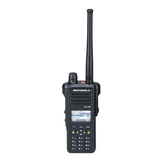
Motorola APX 2000 Detailed Service Manual (1096 pages)
Brand:
Motorola
| Category:
Two-Way Radio
| Size: 57.49 MB
Table of Contents
Table of Contents
11
Computer Software Copyrights
2
Disclaimer
2
Document Copyrights
2
Foreword
2
Manual Revisions
2
Product Safety and Rf Exposure Compliance
2
Trademarks
2
Document History
5
Commercial Warranty
7
Table of Contents
11
List of Tables
14
List of Figures
16
Chapter 1 Introduction
23
General
23
Notations Used in this Manual
24
Chapter 2 Radio Power
25
General
25
Table 2-1. IMPRES Batteries
25
DC Power Routing
26
Figure 2-1. DC Power Distribution
26
Chapter 3 Theory of Operation
27
Figure 3-1. APX 2000/ APX 4000/ APX 4000Li Overall Block Diagram
28
Figure 3-2. APX 1000 (900 Mhz) Overall Block Diagram
29
Main Board
30
Figure 3-3. Transceiver (VHF) Block Diagram (Power and Control Omitted)
30
Figure 3-4. Transceiver (UHF1/UHF2) Block Diagram (Power and Control Omitted)
31
Figure 3-5. Transceiver (700/800 Mhz) Block Diagram (Power and Control Omitted)
32
Table 3-1. Battery Connector J3
33
Figure 3-6. Transceiver (900 Mhz) Block Diagram (Power and Control Omitted)
33
Figure 3-7. Receiver Block Diagram (VHF)
34
Figure 3-8. Receiver Block Diagram (UHF1/UHF2)
35
Figure 3-9. Receiver Block Diagram (700/800 Mhz )
35
Figure 3-10. Receiver Block Diagram (900 Mhz )
35
Figure 3-11. Transmitter Block Diagram (VHF/UHF1/UHF2/900 Mhz)
37
Figure 3-12. Transmitter Block Diagram (700/800 Mhz)
38
Figure 3-13. Synthesizer Block Diagram (VHF)
42
Figure 3-14. Synthesizer Block Diagram (UHF1/UHF2)
43
Figure 3-15. Synthesizer Block Diagram (700/800 Mhz)
43
Figure 3-16. Synthesizer Block Diagram (900 Mhz)
44
Controller
49
Figure 3-17. Controller Interconnection Diagram
49
Figure 3-18. Controller Electrical Overview
51
Figure 3-19. Controller DC Block Diagram
52
Table 3-2. DC Supplies and Sources for Controller
53
Table 3-3. Mako's LDO and Supplies
54
Figure 3-20. V_SW_1.4 Switched Power Supply
55
Table 3-4. Pulse Switching Combination
56
Figure 3-21. 5V Switched Power Supply
56
Figure 3-22. Power-Up Timing Regulators
57
Figure 3-23. Controller Clock Architecture
58
Table 3-5. Controller Clock Distribution
59
Figure 3-24. Overview of OMAP Interconnection with Controller Peripherals
60
Figure 3-25. OMAP Memory Interface
61
Figure 3-26. RX/ TX SSI Configuration
62
Figure 3-27. Audio SSI Configuration
63
Figure 3-28. SPI and I2C Configuration
64
Figure 3-29. CPLD Block Diagram
65
Figure 3-30. Audio TX Path Block Diagram
66
Figure 3-31. RX Audio Path Block Diagram
67
Figure 3-32. Control Top Block Diagram (APX 2000/ APX 4000/ APX 4000Li/ APX 1000 (900 Mhz))
68
Figure 3-33. Control Top Block Diagram (APX 2000/ APX 4000 (Two Knobs))
69
Figure 3-34. Display Circuit Detail Overview Block Diagram
70
Table 3-6. Color Schemes
71
Figure 3-35. Lighting Controller Overview
72
Table 3-7. Key Map Matrix
73
Figure 3-36. Keypad Interface Outline
73
Figure 3-37. GCAI Signal Configuration
74
Table 3-8. P1 Pin Assignment
75
Figure 3-38. GCAI Connector
75
Table 3-9. GCAI Connector Pin Assignment
76
Figure 3-39. APX 2000/ APX 4000 Encryption Architecture
77
Table 3-10. Secure Keypad KIT Numbers
78
Global Positioning Sytem (GPS)
79
Table 3-11. Power and I/O Pins for NL5500
80
Figure 3-40. GPS Block Diagram
80
Accelerometer
81
Table 3-12. SPI Interface
81
Figure 3-41. Accelerometer Block Diagram
81
Table 3-13. Register Address Map
82
Bluetooth
83
Figure 3-42. Relation of Bluetooth & LF Antenna Assembly to Main & Keypad Boards
83
Figure 3-43. Bluetooth Connection Flowchart
84
Figure 3-44. Bluetooth/Controller Interface with Clock Sources
85
Figure 3-45. Bluetooth Functional Block Diagram
85
Figure 3-46. Bluetooth Low-Frequency Circuit Block Diagram
86
Figure 3-47. Bluetooth Low-Frequency Pairing Data Path
86
Figure 3-48. Detailed Low-Frequency Transmit/Receive Paths
87
Figure 3-49. Chip Power-Up/Power-Down Sequence (Exernal Input/Output Shown)
87
Figure 3-50. Current Distribution Tree for Bluetooth Circuitry
88
Table 3-14. Bluetooth Host Processor UART I/O
89
Table 3-15. SPI I/O
90
Figure 3-51. Bluetooth LF UART Connection Block Diagram
90
Table 3-16. USB I/O
91
Figure 3-52. Bluetooth USB Interface to Main Board
91
Table 3-17. GPIO I/O
92
Chapter 4 Troubleshooting Procedures
93
Handling Precautions
93
Recommended Service Tools
94
Table 4-1. Recommended Service Tools
94
Standard Bias Table
95
Table 4-2. Standard Operating Bias - DC Voltages
95
Table 4-3. Standard Operating Bias - Clock Sources
95
Power-Up Self-Check Errors
96
Table 4-4. Power-Up Self-Check Error Codes
96
Power-Up Self-Check Diagnostics and Repair (Not for Field Use)
97
Table 4-5. Power-Up Self-Check Diagnostic Actions
97
Chapter 5 Troubleshooting Charts
99
List of Troubleshooting Charts
99
Table 5-1. Troubleshooting Charts
99
Main Troubleshooting Flowchart
101
Power-Up Failure
102
DC Supply Failure
113
Main Display Failure
120
Volume/Channel Error
121
Volume Set Error (APX 2000/ APX 4000 (Two Knobs))
122
Channel Select Error (APX 2000/ APX 4000 (Two Knobs))
123
Keypad Error
124
5.10 Side Button Error
125
5.11 RX Audio Error
126
5.12 TX Audio Error
128
5.13 Keyload/Secure Hardware/Memory
130
RX RF Failure
132
5.15 FGU Failure
143
VCO Failure
144
5.17 GPS Failure
150
Bluetooth Failure
152
PA Failure
157
Chapter 6 Troubleshooting Waveforms
163
List of Waveforms
163
Table 6-1. List of Waveforms
163
Clocks
164
Figure 6-1. 32 Khz Clock Waveform
164
Figure 6-2. 4 Mhz Clock Waveform
165
Figure 6-3. 12 Mhz Clock Waveform
166
Figure 6-4. 16.8 Mhz Clock Waveform
167
Figure 6-5. 24 Mhz Clock Waveform
168
Audio SSI
169
Figure 6-6. Audio SSI - Red Tx Waveform
169
Figure 6-7. Audio SSI - Red Rx Waveform
170
Figure 6-8. Audio SSI - Sync. Waveform
171
Figure 6-9. Audio SSI - BCLK. Waveform
172
Rx Ssi
173
Figure 6-10. RX SSI - CLK. Waveform
173
Figure 6-11. RX SSI - da Waveform
174
Figure 6-12. RX SSI - Fsync. Waveform
175
Tx Ssi
176
Figure 6-13. TX SSI - TX CLK. Waveform
176
Figure 6-14. TX SSI - da Waveform
177
Figure 6-15. TX SSI - Fsync. Waveform
178
Spi
179
Figure 6-16. SPI - CLK Waveform
179
Figure 6-17. CS Waveform
180
I2C Bus
181
Figure 6-18. I2C Bus - SCA Waveform
181
Figure 6-19. I2C Bus - SCA 5V Waveform
182
Figure 6-20. I2C Bus - SDA Waveform
183
One Wire
184
Figure 6-21. 1-Wire Waveform
184
Gcai
185
Figure 6-22. GCAI - GPIO0 Waveform
185
Figure 6-23. GCAI - GPIO4 Waveform
186
6.10 Usb
187
Figure 6-24. USB - D- Waveform
187
Figure 6-25. USB - D+ Waveform
188
6.11 Sdram
189
Figure 6-26. SDRAM - CLK Waveform
189
Figure 6-27. SDRAM - CLKX Waveform
190
6.12 Flash Control
191
Figure 6-28. FLASH CONTROL - ADV Waveform
191
Figure 6-29. FLASH CONTROL - CS3 Waveform
192
Figure 6-30. FLASH CONTROL - OE Waveform
193
Figure 6-31. FLASH CONTROL - RDY Waveform
194
Figure 6-32. FLASH CONTROL - WE Waveform
195
6.13 Receive Baseband Signals
196
Figure 6-33. Received Baseband Waveforms
196
6.14 Gps
197
Figure 6-34. GPS TCXO Waveforms
197
Figure 6-35. GPS RTC Waveforms
198
Figure 6-36. GPS UART DATA Waveforms
199
6.15 Bluetooth Troubleshooting Waveforms
200
Table 6-2. Bluetooth Command to TX
200
Table 6-3. Bluetooth Command to RX
201
Table 6-4. Low Frequency Command to TX
201
Table 6-5. Low Frequency Command to RX
201
Table 6-6. Bluetooth Test Points
202
Figure 6-37. Startup Waveforms - Vmax of TP16
203
Figure 6-38. Startup - Timing Difference of TP9 to TP16
204
Figure 6-39. Startup - Timing Difference of TP5 to TP16 and Voltage Statistics
205
Figure 6-40. Startup - Timing Difference of TP4 to TP16 and Time Statistics
206
Figure 6-41. Startup - Timing Difference of TP4 to TP5 and Time Statistics
207
Figure 6-42. Startup - Vmax of TP5 and Time Statistics
208
Figure 6-43. Startup - Vmax of TP4 and Time Statistics
209
Figure 6-44. Startup - Vmax of TP5 and Voltage Statistics
210
Figure 6-45. Startup - Vmax of TP9 and Voltage Statistics
211
Figure 6-46. Startup - Vmax of TP10 and Time Statistics
212
Figure 6-47. Startup - Vmax of TP16 and Voltage Statistics
213
Figure 6-48. Startup - Vmax of TP13 and Voltage Statistics
214
Figure 6-49. Startup - Vmax of TP11 and Voltage Statistics
215
Figure 6-50. Startup - Timing Difference of TP13 to TP16 and Time Statistics
216
Figure 6-51. Startup - Timing Difference of TP10 to TP13 and Time Statistics
217
Figure 6-52. Startup - Timing Difference of TP11 to TP13 and Time Statistics
218
Figure 6-53. Bluetooth CW on Spectrum Analyzer
219
6.16 Bluetooth Steady-State
220
Figure 6-54. Keypad Board - USB D+ Vmax and Packet Timing with Statistics
220
Figure 6-55. Keypad Board - USB D- Vmax and Packet Timing with Statistics
221
Figure 6-56. Keypad Board - VSW_3.6 Voltage Statistics
222
Figure 6-57. Keypad Board - 32 Khz Clock Vmax with Statistics
223
Figure 6-58. Keypad Board Waveforms - LF Coil When TX and RX
224
6.17 LF CW on Spectrum Analyzer
225
Figure 6-59. LF CW on Spectrum Analyzer
225
Chapter 7 Troubleshooting Tables
227
List of Board and IC Signals
227
Table 7-2. Mainboard to Back Kit Flex Connector Interface Pin-Out
228
Table 7-3. Main Back Kit Flex Connector to Main Board Connector Interface Pin-Out
231
Table 7-4. Main Back Kit Flex Connector to Keypad Board Connector Interface Pin-Out
234
Table 7-5. Keypad Board Connector to Mainboard Interface Pin-Out
237
Table 7-6. Keypad Board Connector to Front Kit Flex Interface Pin-Out
240
Table 7-7. Front Kit Connector Interface Pin-Out
242
Table 7-8. GCAI Flex Connector Interface Pin-Out
247
Table 7-9. PTT Flex Connector Interface Pin-Out
249
Table 7-10. Mainboard to Back Kit Flex Connector Interface Pin-Out
250
Table 7-11. Main Back Kit Flex Connector to Main Board Connector Interface Pin-Out
252
Table 7-12. Main Back Kit Flex Connector to Keypad Board Connector Interface Pin-Out
255
Table 7-13. Keypad Board Connector to Mainboard Interface Pin-Out
258
Table 7-14. Keypad Board Connector to Front Kit Flex Interface Pin-Out
261
Table 7-15. Front Kit Connector Interface Pin-Out
264
Table 7-16. GCAI Flex Connector Interface Pin-Out
269
Table 7-17. PTT Flex Connector Interface Pin-Out
271
Table 7-18. Overall GPIO Pin Functions
272
Table 7-19. Primary IC Reference Designator
280
Chapter 8 Schematics, Boards Overlays, and Parts Lists
281
List of Transceiver Schematics and Board Overlays
281
Table 8-1. List of Transceiver Schematics and Board Overlays
281
Figure 8-1. Transceiver (RF) Mainboard Overall Schematic (84012320001)
281
Figure 8-36. Transceiver (RF) Board Layout - Top Side (84012320001)
281
Figure 8-37. Transceiver (RF) Board Layout - Bottom Side (84012320001)
281
Figure 8-40. Transceiver (RF) Mainboard Overall Schematic (84012313002)
281
Figure 8-75. Transceiver (RF) Board Layout - Top Side (84012313002)
282
Figure 8-76. Transceiver (RF) Board Layout - Bottom Side (84012313002)
282
Figure 8-79. Transceiver (RF) Mainboard Overall Schematic (84012432001)
282
Figure 8-114.Transceiver (RF) Board Layout - Top Side (84012432001)
282
Figure 8-115.Transceiver (RF) Board Layout - Bottom Side (84012432001)
282
Figure 8-118.Transceiver (RF) Board Overall Schematic (84012266001)
282
Figure 8-152.Transceiver (RF) Board Layout - Top Side (84012266001)
282
Figure 8-153.Transceiver (RF) Board Layout - Bottom Side (84012266001)
282
Transceiver (RF) Boards: VHF (84012320001 / PC000352A01)
285
Figure 8-4. Controller Mainboard Circuit
288
Figure 8-5. ANTSWI Circuit
289
Figure 8-6. TX HF Circuit
290
Figure 8-7. Power Amplifier (PA) Circuit
291
Figure 8-8. Automatic Level Control Circuit
292
Figure 8-9. Receiver Front End Circuit
293
Figure 8-12. Receiver VCO Circuit
296
Figure 8-13. Transmitter VCO Circuit
297
Figure 8-14. DC Circuit
298
Figure 8-15. RF Interconnects Circuit
299
Figure 8-16. CPLD Circuit
300
Figure 8-17. OMAP User Interface Circuit
301
Figure 8-18. Memory Interface Circuit (84012320001)
302
Figure 8-19. Memory Interface Circuit (PC000352A01)
303
Figure 8-20. Audio Circuit (84012320001)
304
Figure 8-21. Audio Circuit (PC000352A01)
305
Figure 8-22. MAKO/DC Distribution Circuit (84012320001)
306
Figure 8-23. MAKO/DC Distribution Circuit (PC000352A01)
307
Figure 8-24. Serial Interface Circuit
308
Figure 8-25. GPS Bluetooth Circuit
309
Figure 8-26. Controller Circuit (84012320001)
310
Figure 8-27. Controller Circuit (PC000352A01)
311
Figure 8-28. Display/Keypad Lighting Control Circuit (84012320001)
312
Figure 8-29. Display/Keypad Lighting Control Circuit (PC000352A01)
313
Figure 8-30. LCD and Keypad Connector Circuit (84012320001)
314
Figure 8-31. LCD and Keypad Connector Circuit (PC000352A01)
315
Figure 8-32. GCAI MACE BT Interconnect Circuit (84012320001)
316
Figure 8-33. GCAI MACE BT Interconnect Circuit (PC000352A01)
317
Figure 8-38. Transceiver (RF) Board Layout - Top Side (PC000352A01)
322
Figure 8-39. Transceiver (RF) Board Layout - Bottom Side (PC000352A01)
323
Transceiver (RF) Boards: UHF1 (84012313002 / PC000353A01)
363
Figure 8-43. Controller Mainboard Circuit
366
Figure 8-44. DC Circuit
367
Figure 8-45. Receiver Back End Circuit
368
Figure 8-46. Receiver Front End Circuit
369
Figure 8-47. ANTSWI Circuit
370
Figure 8-48. Automatic Level Control Circuit
371
Figure 8-49. Receiver Back End Circuit
372
Figure 8-52. Power Amplifiercircuit
375
Figure 8-53. Transmitter HF Circuit
376
Figure 8-54. Receiver VCO Circuit
377
Figure 8-55. Transmitter VCO Circuit
378
Figure 8-56. CPLD Circuit
379
Figure 8-57. OMAP User Interface Circuit
380
Figure 8-58. Memory Interface Circuit (84012313002)
381
Figure 8-59. Memory Interface Circuit (PC000353A01)
382
Figure 8-60. Audio Circuit (84012313002)
383
Figure 8-61. Audio Circuit (PC000353A01)
384
Figure 8-62. MAKO/DC Distribution Circuit (84012313002)
385
Figure 8-63. MAKO/DC Distribution Circuit (PC000353A01)
386
Figure 8-64. Serial Interface Circuit
387
Figure 8-65. RF Interconnects Circuit
388
Figure 8-66. Controller Circuit (84012313002)
389
Figure 8-67. Controller Circuit (PC000353A01)
390
Figure 8-68. Display/Keypad Lighting Control Circuit (84012313002)
391
Figure 8-69. Display/Keypad Lighting Control Circuit (PC000353A01)
392
Figure 8-70. LCD and Keypad Connector Circuit (84012313002)
393
Figure 8-71. LCD and Keypad Connector Circuit (PC000353A01)
394
Figure 8-72. GCAI MACE BT Interconnect Circuit (84012313002)
395
Figure 8-73. GCAI MACE BT Interconnect Circuit (PC000353A01)
396
Figure 8-74. GPS Bluetooth Circuit
397
Figure 8-77. Transceiver (RF) Board Layout - Top Side (PC000353A01)
400
Figure 8-78. Transceiver (RF) Board Layout - Bottom Side (PC000353A01)
401
Transceiver (RF) Boards: UHF2 (84012432001 / PC000354A01)
441
Figure 8-82. Controller Mainboard Circuit
444
Figure 8-83. DC Circuit
445
Figure 8-84. Transmitter HF Circuit
446
Figure 8-85. Power Amplifier Circuit
447
Figure 8-86. Automatic Level Control Circuit
448
Figure 8-87. Receiver Front End Circuit
449
Figure 8-90. Receiver VCO Circuit
452
Figure 8-91. Transmitter VCO Circuit
453
Figure 8-94. DC Circuit
456
Figure 8-95. RF Interconnects Circuit
457
Figure 8-96. CPLD Circuit
458
Figure 8-97. OMAP User Interface Circuit
459
Figure 8-98. Memory Interface Circuit (84012432001)
460
Figure 8-99. Memory Interface Circuit (PC000354A01)
461
Figure 8-100.Audio Circuit (84012432001)
462
Figure 8-101.Audio Circuit (PC000354A01)
463
Figure 8-102.MAKO/DC Distribution Circuit (84012432001)
464
Figure 8-103.MAKO/DC Distribution Circuit (PC000354A01)
465
Figure 8-104.Serial Interface Circuit
466
Figure 8-105.GPS Bluetooth Circuit
467
Figure 8-106.Controller Circuit (84012432001)
468
Figure 8-107.Controller Circuit (PC000354A01)
469
Figure 8-108.Display/Keypad Lighting Control Circuit (84012432001)
470
Figure 8-109.Display/Keypad Lighting Control Circuit (PC000354A01)
471
Figure 8-110.LCD and Keypad Connector Circuit (84012432001)
472
Figure 8-111.LCD and Keypad Connector Circuit (PC000354A01)
473
Figure 8-112.GCAI MACE BT Interconnect Circuit (84012432001)
474
Figure 8-113.GCAI MACE BT Interconnect Circuit (PC000354A01)
475
Figure 8-116.Transceiver (RF) Board Layout - Top Side (PC000354A01)
478
Figure 8-117.Transceiver (RF) Board Layout - Bottom Side (PC000354A01)
479
Transceiver (RF) Boards: 700 - 800 Mhz (84012266001 / PC000351A01)
519
Figure 8-121.Controller Mainboard Circuit
522
Figure 8-122.DC Circuit
523
Figure 8-123.Receiver Back End Circuit
524
Figure 8-124.Receiver Front End Circuit
525
Figure 8-125.ANTSWI Circuit
526
Figure 8-126.Automatic Level Control Circuit
527
Figure 8-127.Receiver Back End Circuit
528
Figure 8-130.Power Amplifiercircuit
531
Figure 8-131.Transmitter HF Circuit
532
Figure 8-132.VCO Circuit
533
Figure 8-133.CPLD Circuit
534
Figure 8-134.OMAP User Interface Circuit
535
Figure 8-135.Memory Interface Circuit (84012266001)
536
Figure 8-136.Memory Interface Circuit (PC000351A01)
537
Figure 8-137.Audio Circuit (84012266001)
538
Figure 8-138.Audio Circuit (PC000351A01)
539
Figure 8-139.MAKO/DC Distribution Circuit (84012266001)
540
Figure 8-140.MAKO/DC Distribution Circuit (PC000351A01)
541
Figure 8-141.Serial Interface Circuit
542
Figure 8-142.RF Interconnects Circuit
543
Figure 8-143.Controller Circuit (84012266001)
544
Figure 8-144.Controller Circuit (PC000351A01)
545
Figure 8-145.Display/Keypad Lighting Control Circuit (84012266001)
546
Figure 8-146.Display/Keypad Lighting Control Circuit (PC000351A01)
547
Figure 8-147.LCD and Keypad Connector Circuit (84012266001)
548
Figure 8-148.LCD and Keypad Connector Circuit (PC000351A01)
549
Figure 8-149.GCAI MACE BT Interconnect Circuit (84012266001)
550
Figure 8-150.GCAI MACE BT Interconnect Circuit (PC000351A01)
551
Figure 8-151.GPS Bluetooth Circuit
552
Figure 8-154.Transceiver (RF) Board Layout - Top Side(PC000351A01)
555
Figure 8-155.Transceiver (RF) Board Layout - Bottom Side (PC000351A01)
556
Transceiver (RF) Boards: 900 Mhz (84012478001)
595
Figure 8-156.Transceiver (RF) Board Overall Schematic
595
Figure 8-157.Controller Mainboard Circuit
596
Figure 8-158.DC Circuit
597
Figure 8-159.Receiver Back End Circuit
598
Figure 8-160.Receiver Front End Circuit
599
Figure 8-161.ANTSWI Circuit
600
Figure 8-162.Automatic Level Control Circuit
601
Figure 8-163.Receiver Back End Circuit
602
Figure 8-166.Power Amplifier Circuit
605
Figure 8-167.Transmitter HF Circuit
606
Figure 8-168.Receive and Transmit VCO Circuit
607
Figure 8-169.CPLD Circuit
608
Figure 8-170.OMAP User Interface Circuit
609
Figure 8-171.Memory Interface Circuit
610
Figure 8-172.Audio Circuit
611
Figure 8-173.MAKO/DC Distribution Circuit
612
Figure 8-174.Serial Interface Circuit
613
Figure 8-175.RF Interconnects Circuit
614
Figure 8-176.Controller Circuit
615
Figure 8-177.Display/Keypad Lighting Control Circuit
616
Figure 8-178.LCD and Keypad Connector Circuit
617
Figure 8-179.GCAI MACE BT Interconnect Circuit
618
Figure 8-180.GPS Bluetooth Circuit
619
Figure 8-181.Transceiver (RF) Board Layout - Top Side
620
Figure 8-182.Transceiver (RF) Board Layout - Bottom Side
621
Keypad Board (84012282001)
639
Figure 8-183.Keypad Board Overall Circuit Schematic (Basic)
639
Figure 8-184.Keypad Matrix Circuit (Basic)
640
Figure 8-185.Keypad Board Overall Circuit Schematic (Expanded)
641
Figure 8-186.Keypad Matrix Circuit (Expanded)
642
Figure 8-187.GPS Bluetooth Circuit
643
Figure 8-188.MACE Circuit
644
Figure 8-189.Keypad Board Layout - Top Side
645
Figure 8-190.Keypad Board Layout - Bottom Side
646
Keypad Lite Board (84012559002)
661
Figure 8-191.Keypad Lite Board Overall Circuit Schematic
661
Figure 8-192.Keypad Lite Matrix Circuit
662
Figure 8-193.Keypad Lite Board Layout - Top Side
663
Figure 8-194.Keypad Lite Board Layout - Bottom Side
664
Keypad Board (APX 2000/ APX 4000 (Two Knobs)) (PC000356A02 (Model 2) / PC000356A01 (Model 3))
667
Figure 8-195.Keypad Board Overall Circuit Schematic (Expanded)
667
Figure 8-196.Keypad Matrix Circuit (Expanded)
668
Figure 8-197.GPS Bluetooth Circuit
669
Figure 8-198.MACE Circuit
670
Figure 8-199.Keypad Board Layout - Top Side
671
Figure 8-200.Keypad Board Layout - Bottom Side
672
Glossary
685
Advertisement
Motorola APX 2000 Basic Service Manual (526 pages)
APX TWO-WAY RADIOS
Brand:
Motorola
| Category:
Two-Way Radio
| Size: 53.43 MB
Table of Contents
Table of Contents
9
Foreword
2
Computer Software Copyrights
2
Disclaimer
2
Document Copyrights
2
Manual Revisions
2
Product Safety and Rf Exposure Compliance
2
Trademarks
2
Document History
4
Commercial Warranty
5
Table of Contents
9
Model Numbering, Charts, and Specifications
15
Portable Radio Model Numbering System
15
ASTRO APX 2000/APX 4000/APX 4000Li VHF Model Chart
17
ASTRO APX 2000/APX 4000/APX 4000Li VHF Model Chart (Continued)
18
ASTRO APX 2000/APX 4000/APX 4000Li UHF1 Model Chart
19
ASTRO APX 2000/APX 4000/APX 4000Li UHF1 Model Chart (Continued)
20
ASTRO APX 2000/APX 4000/APX 4000Li UHF2 Model Chart
21
ASTRO APX 2000/APX 4000/APX 4000Li UHF2 Model Chart (Continued)
22
ASTRO APX 2000/APX 4000/APX 4000Li 700/800 Mhz Model Chart
23
ASTRO APX 2000/APX 4000/APX 4000Li 700/800 Mhz Model Chart (Continued)
24
ASTRO APX 4000 900 Mhz Model Chart
25
Specifications for APX 2000/APX 4000/APX 4000Li VHF Radios
26
Specifications for APX 2000/APX 4000/APX 4000Li UHF1 Radios
27
Specifications for APX 2000/APX 4000/APX 4000Li UHF2 Radios
28
Specifications for APX 2000/APX 4000/APX 4000Li 700/800 Mhz Radios
29
Specifications for APX 4000 900 Mhz Radios
30
Chapter 1 Introduction
31
Manual Contents
31
Notations Used in this Manual
31
Radio Description
32
Flashport
32
Table 1-1. ASTRO APX 2000/ APX 4000/ APX 4000Li Basic Features
32
Chapter 2 Basic Maintenance
33
General Maintenance
33
Safe Handling of CMOS and LDMOS Devices
33
Chapter 3 Basic Theory of Operation
35
Major Assemblies
36
Figure 3-1. APX 2000/APX 4000/APX 4000Li Overall Block Diagram
36
Analog Mode of Operation
37
Figure 3-2. Receiver Block Diagram (VHF)
37
Figure 3-3. Receiver Block Diagram (UHF1/UHF2)
37
Figure 3-4. Receiver Block Diagram (700/800 Mhz)
38
Figure 3-5. Receiver Block Diagram (900 Mhz)
38
Figure 3-6. GPS Diagram
38
Figure 3-7. Transmitter (VHF) Block Diagram
40
Figure 3-8. Transmitter (UHF1/UHF2) Block Diagram
40
Figure 3-9. Transmitter (700/800 Mhz) Block Diagram
41
Figure 3-10. Transmitter (900 Mhz) Block Diagram
41
Digital (ASTRO) Mode of Operation
43
Controller Section
43
Figure 3-11. Controller Block Diagram
43
Figure 3-12. Gps/Bluetooth/Accelerometer Block Diagram
45
Chapter 4 Recommended Test Equipment and Service Aids
47
Recommended Test Equipment
47
Table 4-1. Recommended Test Equipment
47
Service Aids
48
Field Programming
48
Table 4-2. Service Aids
48
Chapter 5 Performance Checks
49
Test Equipment Setup
49
Figure 5-1. Performance Checks Test Setup
49
Table 5-1. Initial Equipment Control Settings
50
Display Radio Test Mode
51
Table 5-2. Test-Mode Displays
51
Table 5-3. Test Frequencies (Mhz) - VHF, UHF1, UHF2
53
Table 5-4. Test Frequencies (Mhz)- 700/800 Mhz, 900 Mhz
54
Table 5-5. Test Environments
54
Receiver Performance Checks
56
Table 5-6. Receiver Performance Checks
56
Table 5-7. Receiver Tests for ASTRO Conventional Channels
57
Transmitter Performance Checks
58
Table 5-8. Transmitter Performance Checks - APX 2000/ APX 4000/ APX 4000Li
58
Table 5-9. Transmitter Tests for ASTRO Conventional Channels - APX 2000/ APX 4000/ APX 4000Li
59
Chapter 6 Radio Alignment Procedures
61
Test Setup
61
Figure 6-1. Radio Alignment Test Setup
61
Tuner Main Menu
62
Softpot
62
Figure 6-2. Tuner Software Main Menu
62
Figure 6-3. Typical Softpot Screen
63
Radio Information
64
Transmitter Alignments
64
Figure 6-4. Radio Information Screen
64
Figure 6-5. Reference Oscillator Alignment Screen (VHF)
65
Figure 6-6. Reference Oscillator Alignment Screen (UHF1)
66
Figure 6-7. Reference Oscillator Alignment Screen (UHF2)
66
Figure 6-8. Reference Oscillator Alignment Screen (700/800 Mhz)
67
Figure 6-9. Reference Oscillator Alignment Screen (900 Mhz)
67
Table 6-1. Reference Oscillator Alignment
68
Figure 6-10. Transmit Power Characterization Points Alignment Screen (VHF)
69
Figure 6-11. Transmit Power Characterization Points Alignment Screen (UHF1)
70
Figure 6-12. Transmit Power Characterization Points Alignment Screen (UHF2)
70
Figure 6-13. Transmit Power Characterization Points Alignment Screen (700/800Mhz)
71
Figure 6-14. Transmit Power Characterization Points Alignment Screen (900Mhz)
71
Figure 6-15. Transmit Power Characterization Alignment Screen (VHF)
72
Figure 6-16. Transmit Power Characterization Alignment Screen (UHF1)
73
Figure 6-17. Transmit Power Characterization Alignment Screen (UHF2)
73
Figure 6-18. Transmit Power Characterization Alignment Screen (700/800 Mhz)
74
Figure 6-19. Transmit Power Characterization Alignment Screen (900 Mhz)
74
Figure 6-20. PA Saturation Referencing Alignment Screen (VHF)
75
Figure 6-21. PA Saturation Referencing Alignment Screen (UHF1)
76
Figure 6-22. PA Saturation Referencing Alignment Screen (UHF2)
76
Figure 6-23. PA Saturation Referencing Alignment Screen (700/800 Mhz)
77
Figure 6-24. PA Saturation Referencing Alignment Screen (900 Mhz)
77
Figure 6-25. Transmit Deviation Balance Alignment Screen (VHF)
79
Figure 6-26. Transmit Deviation Balance Alignment Screen (UHF1)
80
Figure 6-27. Transmit Deviation Balance Alignment Screen (UHF2)
80
Figure 6-28. Transmit Deviation Balance Alignment Screen (700/800 Mhz)
81
Figure 6-29. Transmit Deviation Balance Alignment Screen (900 Mhz)
81
Front End Filter Alignment
82
Figure 6-30. Front End Filter Alignment Screen (UHF1)
82
Performance Testing
83
Figure 6-31. Front End Filter Alignment Screen (UHF2)
83
Figure 6-32. Bit Error Rate Screen (VHF)
85
Figure 6-33. Bit Error Rate Screen (UHF1)
85
Figure 6-34. Bit Error Rate Screen (UHF2)
86
Figure 6-35. Bit Error Rate Screen (700/800 Mhz)
86
Figure 6-36. Bit Error Rate Screen (900 Mhz)
87
Figure 6-37. Transmitter Test Pattern Screen (VHF)
88
Figure 6-38. Transmitter Test Pattern Screen (UHF1)
88
Figure 6-39. Transmitter Test Pattern Screen (UHF2)
89
Figure 6-40. Transmitter Test Pattern Screen (700/800 Mhz)
89
Figure 6-41. Transmitter Test Pattern Screen (900 Mhz)
90
Chapter 7 Encryption
91
Load an Encryption Key
91
Table 7-1. Kit Numbers for Secure-Enabled Keypad Boards
91
Multikey Feature
92
Select an Encryption Key
92
Select an Encryption Index
93
Erase an Encryption Key
94
Chapter 8 Disassembly/Reassembly Procedures
95
APX 2000/ APX 4000/ APX 4000Li Exploded View (Main Subassemblies)
95
Table 8-1. APX 2000/ APX 4000/ APX 4000Li Partial Exploded View Parts List
96
Figure 8-1. APX 2000/ APX 4000/ APX 4000Li Partial Exploded View
96
Required Tools and Supplies
97
Fastener Torque Chart
97
Table 8-2. Required Tools and Supplies
97
Table 8-3. Required Tools and Supplies
97
Radio Disassembly
98
Figure 8-2. Lifting up the Latch
98
Figure 8-3. Removing the Battery
99
Figure 8-4. Removing the Antenna
99
Figure 8-5. Removing the Multi Function Knob
100
Figure 8-6. Removing the Thumb Screw
101
Figure 8-7. Disengage the Chassis
102
Figure 8-8. Remove the Chassis Assembly
102
Figure 8-9. Remove the Chassis Screws
103
Figure 8-10. Remove the Secondary Shield Assembly
103
Figure 8-11. Remove the Main O-Ring at the Antenna Holder
104
Figure 8-12. Lift up the Main Board from the Chassis
104
Figure 8-13. Unplug the Back Kit Flex Connectors
105
Figure 8-14. Disengage the Shroud
105
Figure 8-15. Remove the Shroud
105
Figure 8-16. Remove the Keypad Retainer Screws
106
Figure 8-18. Unplug the Front Kit Flex and Back Kit Flex Connectors
107
Figure 8-19. Remove the Keypad Board
107
Figure 8-20. Disengage the Keypad
108
Figure 8-21. Remove the Keypad
108
Serviceable Components of the Main Sub-Assemblies
109
Figure 8-22. Serviceable Components - Main Board Assembly
109
Figure 8-23. Serviceable Components - Chassis Assembly
110
Figure 8-24. Serviceable Components - Main Housing
112
Figure 8-25. Servicing the Multi Function Knob
113
Radio Reassembly
114
Figure 8-26. Assemble the RF Board
114
Figure 8-27. Assemble the Main O-Ring at Antenna Holder
114
Figure 8-28. Assemble the Secondary Shield Assembly
115
Figure 8-29. Torque in the Chassis Screws
115
Figure 8-30. Assemble the Keypad
116
Figure 8-31. Plug in the Front Kit Flex Connector
117
Figure 8-32. Plug in the Back Kit Flex Connectors
117
Figure 8-33. Place Keypad Retainer over the Keypad Board
118
Figure 8-34. Torque in the Keypad Retainer Screws
118
Figure 8-35. Assemble the Shroud
119
Figure 8-36. Slide Chassis Assembly into Front Housing
119
Figure 8-37. Assemble Back Kit and Front Kit Together
119
Figure 8-38. Engaging Hook and Seating Cover
120
Figure 8-39. Securing the Cover
120
Figure 8-40. Reassemble the Multi Function Knob
121
Figure 8-41. Attaching the Antenna
122
Figure 8-42. Assemble the Vacuum Port Seal
122
Figure 8-43. Assemble the Ventilation Label
122
Figure 8-44. Assemble the Bottom Label
123
Figure 8-45. Attaching Battery - Slide into Position
123
Ensuring Radio Submergibility
124
Figure 8-46. Attaching Vacuum Test Fixture
126
Chapter 9 Basic Troubleshooting
129
Power-Up Error Codes
129
Table 9-1. Power-Up Error Code Displays
129
Operational Error Codes
130
Table 9-2. Operational Error Code Displays
130
Receiver Troubleshooting
131
Table 9-3. Receiver Troubleshooting Chart
131
Transmitter Troubleshooting
132
Encryption Troubleshooting
132
Table 9-4. Transmitter Troubleshooting Chart
132
Table 9-5. Encryption Troubleshooting Chart
132
Chapter 10 Exploded Views and Parts Lists
133
Table 10-1. APX 2000/ APX 4000/ APX 4000Li Exploded Views and Controller Kit
133
10.1 APX 2000/ APX 4000/ APX 4000Li Front Kit Exploded View
134
Figure 10-1. APX 2000/ APX 4000/ APX 4000Li Front Kit Exploded View
134
APX 2000/ APX 4000/ APX 4000Li Front Kit Exploded View Parts List
135
10.3APX 2000/ APX 4000/ APX 4000Li Back Kit Exploded View
136
Figure 10-2. APX 2000/ APX 4000/ APX 4000Li Back Kit Exploded View
136
APX 2000/ APX 4000/ APX 4000Li Back Kit Exploded View Parts List
137
Index
139
Motorola APX 2000 User Manual (158 pages)
Brand:
Motorola
| Category:
Two-Way Radio
| Size: 3.2 MB
Table of Contents
Intellectual Property and Regulatory Notices
2
Table of Contents
3
List of Tables
12
Software Version
13
Chapter 1: Read Me First
14
Notations Used in this Manual
14
Radio Care
14
Cleaning Your Radio
16
Cleaning the External Surface of the Radio
16
Radio Service and Repair
16
Battery Recycling and Disposal
17
What Your Dealer or System Administrator Can Tell You
17
Chapter 2: Getting Started
18
Charging the Battery
18
Attaching the Battery
18
Attaching the Antenna
19
Removing and Attaching the Accessory Connector Cover
19
Attaching the Belt Clip
19
Turning on the Radio
19
Adjusting the Volume
20
Chapter 3: Radio Controls
21
Radio Parts and Controls
21
Text Entry Icons
24
Table 1: Text Entry Modes
25
Table 2: Keypad Characters
25
Programmable Features
26
Assignable Radio Functions
26
Assignable Settings or Utility Functions
29
Chapter 4: Status Indicators
30
Battery Charge Status
30
Fuel Gauge Icons
30
Accessing the Battery Info Screen
30
HAZLOC Battery Type Detection
31
LED Indications
31
Table 3: LED Indications
31
Status Icons
32
TMS Status Icons
34
Call Type Icons
34
Table 4: TMS Status Icons
34
Table 5: Call Type Icons
34
Top Lightbar Indicator
35
Intelligent Lighting Indicators
36
Alert Tones
36
Phone Call Displays and Alerts
39
Display Color Change on Channel
39
Chapter 5: General Radio Operation
40
Selecting a Zone
40
Selecting a Radio Channel
40
Selecting a Channel by Using Channel Search Button
41
Mode Select Feature
42
Saving a Zone and a Channel to a Softkey
42
Saving a Zone and a Channel to a Button
42
Receiving and Responding to a Radio Call
43
Receiving and Responding to a Talkgroup Call
43
Receiving and Responding to a Private Call (Trunking Only)
43
Receiving and Responding to a Telephone Call (Trunking Only)
44
Methods to Make a Radio Call
44
Making a Talkgroup Call
44
Making a Private Call (Trunking Only)
45
Making an Enhanced Private Call (Trunking Only)
45
Making a Telephone Call (Trunking Only)
46
Switching between Repeater or Direct Operation Button
46
Monitor Feature
47
Monitoring a Channel
47
Monitoring Conventional Mode
47
Chapter 6: Additional Performance Enhancement
49
ASTRO 25 Enhanced Data
49
Dynamic System Resilience
49
Crosstalk Prevention
49
Encrypted Integrated Data
49
Securenet
49
Over-The-Air Rekeying
49
P25 Digital Vehicular Repeater System
50
Conventional Talkgroup and Radio Scan Enhancements
50
Advertisement
Motorola APX 2000 User Manual (206 pages)
MODEL 3
Brand:
Motorola
| Category:
Two-Way Radio
| Size: 7.09 MB
Table of Contents
Display Status Icons
4
Menu Navigation
4
Sending a Silent Emergency Call
4
Table of Contents
5
Declaration of Conformity
12
Important Safety Information
14
Software Version
15
Notice to Users (FCC and Industry Canada)
15
Consignes de Sécurité Importantes
16
Version Logicielle
17
Avis Aux Utilisateurs (FCC Et Industrie Canada)
17
Computer Software Copyrights
18
Documentation Copyrights
19
Disclaimer
20
Getting Started
21
How to Use this Guide
21
Notations Used in this Manual
21
Additional Performance Enhancement
22
ASTRO 25 Enhanced Data
22
Dynamic System Resilience (DSR)
22
Crosstalk Prevention
22
Encrypted Integrated Data (EID)
22
Securenet
22
Conventional Talkgroup and Radio Scan Enhancements
22
What Your Dealer/System Administrator Can Tell You
23
Preparing Your Radio for Use
24
Charging the Battery
24
Attaching the Battery
24
Attaching the Antenna
26
Removing and Attaching the Accessory Connector Cover
28
Attaching the Belt Clip
29
Turning on the Radio
31
Adjusting the Volume
33
Identifying Radio Controls
35
Radio Parts and Controls
35
Programmable Features
38
Assignable Radio Functions
38
Assignable Settings or Utility Functions
42
Accessing the Preprogrammed Functions
42
Menu Select Buttons
43
Home Button
43
4-Way Navigation Button
43
Data Feature Button
44
Multi-Function Knob (MFK)
44
Keypad
44
Keypad Characters - Uppercase Mode
45
Keypad Characters - Lowercase Mode
46
Keypad Characters - Numeric Mode
47
Keypad Characters - Hexadecimal Mode
48
Push-To-Talk (PTT) Button
49
Identifying Status Indicators
51
Status Icons
51
Text Messaging Service (TMS) Indicators
54
TMS Status Icons
54
TMS Menu Options
56
Call Type Icons
56
LED Indicator
57
Top Lightbar Indicator
58
Intelligent Lighting Indicators
59
Alert Tones
60
Phone Call Displays and Alerts
64
General Radio Operation
66
Selecting a Zone
66
Selecting a Radio Channel
66
Selecting a Channel Via Channel Search Button
68
Mode Select Feature
68
Saving a Zone and a Channel to a Softkey
69
Saving a Zone and a Channel to a Button
69
Receiving and Responding to a Radio Call
69
Receiving and Responding to a Talkgroup Call
70
Receiving and Responding to a Private Call (Trunking Only)
70
Receiving and Responding to a Telephone Call (Trunking Only)
71
Making a Radio Call
71
Making a Talkgroup Call
72
Making a Private Call (Trunking Only)
72
Making an Enhanced Private Call (Trunking Only)
73
Making a Telephone Call (Trunking Only)
74
Switching between Repeater or Direct Operation Button
75
Monitor Feature
76
Monitoring a Channel
76
Monitoring Conventional Mode
76
Motorola APX 2000 User Manual (84 pages)
Brand:
Motorola
| Category:
Two-Way Radio
| Size: 1.36 MB
Table of Contents
Intellectual Property and Regulatory Notices
2
Table of Contents
3
List of Tables
8
Software Version
9
Chapter 1: Read Me First
10
Notations Used in this Manual
10
Radio Care
11
Cleaning Your Radio
12
Cleaning the External Surface of the Radio
12
Radio Service and Repair
12
Battery Recycling and Disposal
12
What Your Dealer or System Administrator Can Tell You
13
Chapter 2: Preparing Your Radio for Use
14
Charging the Battery
14
Attaching the Battery
14
Attaching the Antenna
15
Removing and Attaching the Accessory Connector Cover
15
Attaching the Belt Clip
15
Turning on the Radio
15
Adjusting the Volume
16
Chapter 3: Radio Controls
17
Radio Parts and Controls
17
Programmable Features
18
Assignable Radio Functions
18
Assignable Settings or Utility Functions
20
Chapter 4: Status Indicators
21
Battery Charge Status
21
Fuel Gauge Icons
21
HAZLOC Battery Type Detection
21
LED Indications
22
Status Icons
22
Top Lightbar Indicator
24
Intelligent Lighting Indicators
24
Alert Tones
25
Phone Call Displays and Alerts
27
Display Color Change on Channel
27
Chapter 5: General Radio Operation
28
Selecting a Zone
28
Selecting a Radio Channel
28
Mode Select Feature
29
Saving a Zone and a Channel to a Softkey
29
Saving a Zone and a Channel to a Button
29
Receiving and Responding to a Radio Call
29
Receiving and Responding to a Talkgroup Call
30
Receiving and Responding to a Private Call (Trunking Only)
30
Receiving and Responding to a Telephone Call (Trunking Only)
30
Methods to Make a Radio Call
31
Making a Private Call (Trunking Only)
31
Making an Enhanced Private Call (Trunking Only)
31
Switching between Repeater or Direct Operation Button
31
Monitor Feature
32
Monitoring a Channel
32
Monitoring Conventional Mode
32
Chapter 6: Additional Performance Enhancement
34
ASTRO 25 Enhanced Data
34
Dynamic System Resilience
34
Crosstalk Prevention
34
Encrypted Integrated Data
34
Securenet
34
Over-The-Air Rekeying
34
P25 Digital Vehicular Repeater System
35
Conventional Talkgroup and Radio Scan Enhancements
35
Motorola APX 2000 User Manual (92 pages)
Brand:
Motorola
| Category:
Two-Way Radio
| Size: 2.94 MB
Table of Contents
Table of Contents
5
Declaration of Conformity
10
Important Safety Information
12
Software Version
13
Notice to Users (FCC and Industry Canada)
13
Consignes de Sécurité Importantes
14
Version Logicielle
15
Avis Aux Utilisateurs (FCC Et Industrie Canada)
15
Computer Software Copyrights
16
Documentation Copyrights
17
Disclaimer
18
Getting Started
19
How to Use this Guide
19
Notations Used in this Manual
19
Additional Performance Enhancement
19
Dynamic System Resilience (DSR)
19
Crosstalk Prevention
19
Conventional Talkgroup and Radio Scan Enhancements
20
What Your Dealer/System Administrator Can Tell You
20
Preparing Your Radio for Use
21
Charging the Battery
21
Attaching the Battery
21
Attaching the Antenna
22
Removing and Attaching the Accessory Connector Cover
23
Attaching the Belt Clip
24
Turning on the Radio
24
Adjusting the Volume
25
Identifying Radio Controls
27
Radio Parts and Controls
27
Programmable Features
28
Assignable Radio Functions
28
Assignable Settings or Utility Functions
30
Accessing the Preprogrammed Functions
30
Menu Select Buttons
31
Multi-Function Knob (MFK)
31
Push-To-Talk (PTT) Button
32
Identifying Status Indicators
33
Status Icons
33
LED Indicator
35
Top Lightbar Indicator
36
Intelligent Lighting Indicators
37
Alert Tones
38
Phone Call Displays and Alerts
41
General Radio Operation
42
Selecting a Zone
42
Selecting a Radio Channel
42
Mode Select Feature
43
Saving a Zone and a Channel to a Softkey
43
Saving a Zone and a Channel to a Button
43
Receiving and Responding to a Radio Call
44
Receiving and Responding to a Talkgroup Call
44
Receiving and Responding to a Private Call (Trunking Only)
44
Receiving and Responding to a Telephone Call (Trunking Only)
45
Switching between Repeater or Direct Operation Button
46
Monitor Feature
46
Monitoring a Channel
46
Monitoring Conventional Mode
47
Advanced Features
48
Advanced Call Features
48
Selective Call (ASTRO Conventional Only)
48
Responding to the Dynamic Regrouping Feature (Trunking Only)
48
Scan Lists
49
Viewing a Scan List
50
Viewing and Changing the Priority Status
50
Scan
50
Turning Scan on or off
50
Making a Dynamic Priority Change (Conventional Scan Only)
51
Deleting a Nuisance Channel
51
Restoring a Nuisance Channel
52
Motorola APX 2000 Quick Reference Manual (47 pages)
Brand:
Motorola
| Category:
Two-Way Radio
| Size: 29.73 MB
Table of Contents
Sending an Emergency Call
4
Sending a Silent Emergency Call
4
Menu Navigation
4
Navigation Dans Le Menu
8
Controlli Della Radio
9
Accensione/Spegnimento Della Radio
9
Ricezione E Trasmissione
9
Recepción y Transmisión
11
Enviar Uma Chamada de Emergência
14
Enviar Uma Chamada de Emergência Silenciosa
14
Een Noodoproep Verzenden
16
Een Stille Noodoproep Verzenden
16
Sender Et Nødopkald
18
Sender Et Lydløst Nødopkald
18
Skicka Ett Nödanrop
20
Skicka Ett Ljudlöst Nödanrop
20
Ενεργοποίηση/Απενεργοποίηση Ασύρματου Πομποδέκτη
25
Αποστολή Κλήσης Έκτακτης Ανάγκης
26
Αποστολή Αθόρυβης Κλήσης Έκτακτης Ανάγκης
26
Πλοήγηση Στο Μενού
26
Ārkārtas Zvana Sūtīšana
28
Klusā Ārkārtas Zvana Sūtīšana
28
Uskutočnenie Pohotovostného Hovoru
30
Uskutočnenie Tichého Pohotovostného Hovoru
30
Acil Durum Çağrısı Gönderme
32
Sessiz Acil Durum Çağrısı Gönderme
32
Menüde Gezinme
32
Pornirea/Oprirea Radioului
37
Efectuarea Unui Apel de Urgenţă
38
Trimiterea Unui Apel de Urgenţă Silenţios
38
Элементы Управления
39
Включение И Выключение Радиостанции
39
Отправка Экстренного Вызова В Беззвучном Режиме
40
Навигация По Меню
40
Motorola APX 2000 Quick Reference Card (2 pages)
Digital Portable Radios
Brand:
Motorola
| Category:
Portable Radio
| Size: 0.59 MB
Advertisement
Related Products
Motorola APX 2000 2
Motorola APX 2000 MODEL 2
Motorola APX 2000 1
Motorola APX 2000 3
Motorola APX 2
Motorola APX Series 8000-3
Motorola Astro APX 6000Li 1
Motorola APX 8000H
Motorola APX 6500Li
Motorola APX 4500 O2 CH
Motorola Categories
Cell Phone
Two-Way Radio
Baby Monitor
Cordless Telephone
Radio
More Motorola Manuals
Login
Sign In
OR
Sign in with Facebook
Sign in with Google
Upload manual
Upload from disk
Upload from URL