Sign In
Upload
Manuals
Brands
Mitsubishi Manuals
Touch terminals
GOT2000 Series
Mitsubishi GOT2000 Series Manuals
Manuals and User Guides for Mitsubishi GOT2000 Series. We have
3
Mitsubishi GOT2000 Series manuals available for free PDF download: Connection Manual, User Manual, Supplementary Description
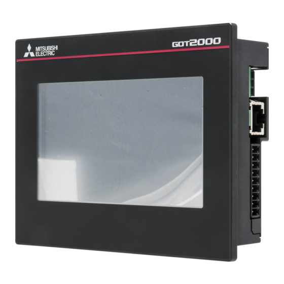
Mitsubishi GOT2000 Series Connection Manual (674 pages)
GRAPHIC OPERATION TERMINAL
Brand:
Mitsubishi
| Category:
Touch terminals
| Size: 22.88 MB
Table of Contents
Introduction
10
Safety Precautions
3
Table of Contents
10
List of Manuals for GT Works3
20
Abbreviations and Generic Terms
21
Preparatory Procedures
25
1 Preparatory Procedures for Monitoring
25
Setting the Communication Interface
27
Setting Connected Equipment (Channel Setting)
28
I/F Communication Setting
34
Precautions
36
Writing the Package Data Onto the GOT
37
Checking the Package Data Writing on GOT
38
Option Devices for the Respective Connection
39
Communication Module
39
Conversion Cables
40
Option Unit
40
Serial Multi-Drop Connection Unit
40
Installing a Unit on Another Unit (Checking the Unit Installation Position)
41
Connection Cables for the Respective Connection
44
GOT Connector Specifications
44
Coaxial Cableconnector Connection Method
45
Terminating Resistors of GOT
46
Verifying GOT Recognizes Connected Equipment
47
Checking for Normal Monitoring
49
Check on the GOT
49
Confirming the Communication State on the GOT Side (for Ethernet Connection)
53
Confirming the Communication State to each Station (Station Monitoring Function)
55
Check on GX Developer
57
Check on GX Works2
61
Check on the PLC
61
Mitsubishi Plc Connections
63
2 Device Range that Can be Set
65
MELSEC-Q/QS, Q17Nd/M/Nc/Dr, Crnd-700
65
Device Range that Can be Set
66
MELSEC-Qna, MELDAS C6 *
66
Melsec-L
74
Melsec-A
75
Melsec-Fx
76
Melsec-Ws
77
3 Access Range for Monitoring
81
Access Range for Monitoring Stations on Network Systems
82
MELSECNET/H, MELSECNET/10, CC-Link IE Controller Network, CC-Link IE Field Network
82
Access Range for Monitoring
82
Access Range for Monitoring When Using Ethernet Connection
93
Ethernet Connection
93
CC-Link System Access Range for Monitoring
94
Data Link System (MELSECNET/B, (II)) Access Range for Monitoring
97
Access Range for Monitoring When Connecting FXCPU
98
Connection to Remote I/O Station in MELSECNET/H Network System
99
Direct Connection to Cpu
100
Computer Link Connection
100
Connection to the Head Module of CC-Link IE Field Network System
102
4 How to Monitor Reduntant System
103
Connection to Remote I/O Station in MELSECNET/H Network System
110
Direct CPU Connection (Direct CPU Connection to the Remote I/O Station)
110
Computer Link Connection (Connection to Serial Communication Module Mounted on Remote I/O Station)
111
Ethernet Connection (Connection to Ethernet Module Mounted on Remote I/O Station)
112
Direct CPU Connection
113
When Using One GOT
113
When Using Two Gots
114
Precautions When Connecting a GOT Directly to a PLC CPU in the Redundant System Without Making Q Redundant Setting
115
CC-Link Connection (Intelligent Device Station)
120
CC-Link Connection (Via G4)
122
MELSECNET/H and MELSECNET/10 Connections (Network Systems)
124
Melsecnet/H Connection (Plc to Plc Network), Melsecnet/10 Connection (Plc to Plc Network)
124
CC-Link IE Controller Network Connection (Network System)
125
CC-Link IE CONTROLLER NETWORK CONNECTION
125
Ethernet Connection
126
Connection to the Redundant Type Extension Base Unit
127
Computer Link Connection (Connection to the Serial Communication Module Mounted on the Redundant Type Extension Base Unit)
127
Ethernet Connection (Connection to the Ethernet Module Mounted on Redundant Type Extension Base Unit)
128
CC-Link Connection (Intelligent Device Station) (Connection to the CC-Link Module Mounted on Redundant Type Extension Base Unit)
129
CC-Link Connection (Intelligent Device Station) (Connection to the CC-Link
129
CC-Link Connection (Via G4) (Connection to the CC-Link Module Mounted on Redundant Type Extension Base Unit)
130
Q Redundant Setting
130
CC-Link CONNECTION (Via G4)
130
Switch the Monitor Target to the Control System Using the Script Function
133
Method for Using the Station Number Switching Function
133
Method for Using the Screen Changing Function
140
5 Ethernet Connection
146
Connectable Model List
146
Plc/Motion Controller CPU
146
Ethernet Module
150
System Configuration
151
Connection to Ethernet Module
151
Connection to Built-In Ethernet Port CPU or C Controller Module
154
Connecting to Display I/F
155
Connection to CC-Link IE Field Network Ethernet Adapter Module
156
Connecting to PERIPHERAL I/F (Built-In Ethernet Port Motion Controller CPU)
157
GOT Side Settings
158
Communication Detail Settings
158
Setting Communication Interface (Communication Settings)
158
Ethernet Setting
159
GOT Ethernet Setting
159
Routing Parameter Setting
160
PLC Side Setting
162
Connecting to Built-In Ethernet Port CPU (One-To-One Connection)
162
Connecting to Built-In Ethernet Port CPU (Multiple Connection)
164
Connecting to Ethernet Module (Q/L Series)
166
Connecting to C Controller Module
169
Connecting to Ethernet Module (Qna Series)
173
Connecting to Ethernet Module (a Series)
181
Connecting to Ethernet Module (FX Series)
181
Connecting to Built-In Ethernet Port FXCPU (FX3GE)
185
Connecting to Display I/F (CNC C70)
187
Connecting to CC-Link IE Field Network Ethernet Adapter Module
189
Connecting to PERIPHERAL I/F (Built-In Ethernet Port Motion Controller CPU)
192
Precautions
195
7. Computer Link Connection
226
Bus Connection
247
8. Bus Connection
257
6 Direct Connection to Cpu
197
Connectable Model List
198
Connecting to QCPU
202
System Configuration
202
Connecting to LCPU
203
Connecting to Qnacpu
204
Connecting to ACPU
205
Connecting to FXCPU
206
Connecting to the Motion Controller CPU
216
Connecting to WSCPU
216
Cable
217
Connection Diagram
217
Communication Detail Settings
218
GOT Side Settings
218
Setting Communication Interface (Communication Settings)
218
Precautions
220
Computer Link Connection
221
Connectable Model List
222
Serial Communication Module/Computer Link Module
226
System Configuration
227
Connecting to LCPU
228
Connecting to QCPU (a Mode)
229
Connecting to Qnacpu (Qnacpu Type)
230
Connecting to Qnacpu (Qnascpu Type)
231
Connecting to ACPU (Ancpu Type)
233
Connecting to ACPU (Anscpu Type, A0J2HCPU, A2CCPUC)
234
Connection Diagram
235
GOT Side Settings
236
PLC Side Setting
239
Connecting Serial Communication Module (Qna Series)
241
Connecting Computer Link Module
242
Precautions
245
Bus Connection
248
Connectable Model List
248
System Configuration
253
Connecting to Qnacpu or Ancpu
257
Connection to Qnascpu or Anscpu
260
Connection to A0J2HCPU
266
Connection to Motion Controller CPU(A273UCPU, A273UHCPU(-S3), A373UCPU(-S3))
267
Connecting to Motion Controller CPU (A171SCPU(-S3(N)), A171SHCPU(N A172SHCPU(N), A173UHCPU(-S1))
272
GOT Side Settings
278
Precautions
282
Powering off the GOT, Reapplying the Power (off to ON)
283
When Connecting Multiple Gots
286
When Using a PLC CPU in the Direct Mode
286
Troubleshooting
287
When Connecting to a Q4ARCPU Redundant System
287
When Monitoring the Q170MCPU, Q170MSCPU(-S1)
287
Melsecnet/H Connection
289
Connectable Model List
290
Plc/Motion Controller CPU
291
MELSECNET/H Network Module
296
MELSECNET/H (NET/10 Mode), MELSECNET/10 Network Module
296
System Configuration
297
Connecting to Optical Loop System
297
Connecting to the Coaxial Bus System
299
GOT Side Settings
301
Setting Communication Interface (Communication Settings)
301
Communication Detail Settings
301
Routing Parameter Setting
302
PLC Side Setting When Connecting to MELSECNET/H
304
System Configuration
304
Switch Setting of MELSECNET/H Network Module
304
Parameter Setting
305
Controller Setting] of GT Designer3
308
PLC Side Setting When Connecting to MELSEC/10
309
Connecting to MELSECNET/H Network Module
309
Connecting to MELSECNET/10 Network Module (Qna Series)
314
Connecting to MELSECNET/10 Network Module (a Series)
318
Precautions
322
CC-Link Ie Controller
325
10 CC-Link IE CONTROLLER NETWORK CONNECTION
325
Connectable Model List
326
Plc/Motion Controller CPU
326
CC-Link IE Controller Network Communication Unit
331
System Configuration
332
Connecting to Optical Loop System
332
GOT Side Settings
333
Communication Detail Settings
333
Setting Communication Interface (Communication Settings)
333
Routing Parameter Setting
334
PLC Side Setting
336
Precautions
342
CC-Link Ie Field
343
Network Connection
343
11 CC-Link IE FIELD NETWORK CONNECTION
344
Connectable Model List
344
Plc/Motion Controller CPU
344
CC-Link IE Field Network Communication Unit
349
System Configuration
350
Connecting to CC-Link IE Field Network Communication Unit
350
GOT Side Settings
351
Communication Detail Settings
351
Setting Communication Interface (Communication Settings)
351
Routing Parameter Setting
352
PLC Side Setting
353
Precautions
356
CC-Link Connection
357
Connectable Model List
358
Plc/Motion Controller CPU
358
CC-Link Module
362
System Configuration
363
Connecting with CC-Link Ver.1 Compatible
363
Connecting with CC-Link Ver.2 Compatible
364
Connecting with CC-Link Ver.1/Ver.2 Compatibles Mixed
365
GOT Side Settings
366
Setting Communication Interface (Communication Settings)
366
Communication Detail Settings
366
PLC Side Setting
368
Connecting to CC-Link Module (Q Series) with Ver.1 Compatible
369
Connecting to CC-Link Module (Q Series) with Ver.2 Compatible
372
Connecting to CC-Link Module (Q Series) with Ver.1/Ver.2 Compatibles Mixed
376
Connecting to MELSEC-L Series with CC-Link Ver.1 Compatible
379
Connecting to MELSEC-L Series with CC-Link Ver.2 Compatible
381
Connecting to CC-Link Module (Qna Series)
382
Connecting to CC-Link Module (a Series)
387
Precautions
395
Precautions
396
CC-Link Connection (Via G4)
397
Connectable Model List
398
Plc/Motion Controller CPU
398
CC-Link Module/Peripheral Module
402
System Configuration
403
Connecting to QCPU (Q Mode)
403
Connecting to LCPU
404
Connection Diagram
405
Cable
405
GOT Side Settings
406
Communication Detail Settings
406
Setting Communication Interface (Communication Settings)
406
PLC Side Settings
408
Connecting AJ65BT-G4-S3
408
Connecting AJ65BT-R2N
409
Network Parameter] of GX Developer
411
Switch Setting of CC-Link Module (Q Series)
411
Parameter Setting (When Connecting to C Controller Module)
412
Controller Setting] of GT Designer3
413
Precautions
414
Mitsubishi Fa Device Connections
415
14 Inverter Connection
417
Connectable Model List
418
System Configuration
419
Connecting to FREQROL-A500/A500L/F500/F500L/V500/V500L
419
Connecting to FREQROL-E500/S500/S500E/F500J/D700/F700PJ
422
Connecting to FREQROL-E700/Sensorless Servo (FREQROL-E700EX)
424
Connecting to FREQROL-A700/F700/700P/A800/F800
427
Connecting to MD-CX522-K(-A0)
430
Connection Diagram
432
Cable
432
GOT Side Settings
437
Setting Communication Interface (Communication Settings)
437
Communication Detail Settings
438
FREQROL Series Inverter Side Settings
440
Connecting FREQROL-S500, S500E, F500J Series
440
Connecting FREQROL-E500 Series
441
Connecting FREQROL-F500, F500L Series
442
Connecting FREQROL-A500, A500L Series
443
Connecting FREQROL-V500, V500L Series
444
Connecting FREQROL-E700 Series
445
Connecting FREQROL-D700 Series
446
Connecting FREQROL-F700/700P Series
447
Connecting FREQROL-F700PJ Series
449
Connecting FREQROL-A700 Series
450
Connecting FREQROL-A800, F800 Series
452
Connecting a Sensorless Servo (FREQROL-E700EX Series)
456
Connecting MD-CX522-K(-A0)
457
Station Number Setting
458
Device Range that Can be Set
459
Precautions
464
15 Servo Amplifier Connection
465
Connectable Model List
466
System Configuration
467
Connecting to the MELSERVO-J2-Super Series
467
Connecting to the MELSERVO-J2M Series
468
Connecting to the MELSERVO-J4, J3 Series
469
Connecting to the MELSERVO-JE Series
472
Connection Diagram
473
Cable
473
Cable
474
GOT Side Settings
476
Communication Detail Settings
476
Setting Communication Interface (Communication Settings)
476
Setting on Servo Amplifier Side
478
Connecting to the MELSERVO-J2-Super Series
478
Connecting to the MELSERVO-J2M Series
479
Connecting to the MELSERVO-J4,J3, JE Series
480
Station Number Setting
480
Device Range that Can be Set
481
Precautions
509
16 Robot Controller Connection
511
Connectable Model List
512
System Configuration
512
Connecting to Robot Controller (Crnd-700)
512
GOT Side Settings
513
Communication Detail Settings
513
Setting Communication Interface (Communication Settings)
513
Ethernet Setting
514
GOT Ethernet Setting
514
PLC Side Settings
515
Connecting to Robot Controller (Crnd-700)
515
Device Range that Can be Set
517
Precautions
517
17 Cnc Connection
519
Connectable Model List
520
System Configuration
521
Direct Connection to CPU
521
MELSECNET/10 Connection (PLC to PLC Network)
522
CC-Link Connection (Intelligent Device Station)
523
Ethernet Connection
524
Connection Diagram
525
Cable
525
GOT Side Settings
526
Communication Detail Settings
526
Setting Communication Interface (Communication Settings)
526
GOT Ethernet Setting
529
Ethernet Setting
530
CNC Side Settings
531
MELSECNET/10 Connection
531
CC-Link (ID) Connection
534
Ethernet Connection
536
Device Range that Can be Set
538
Precautions
538
CC-Link (ID) Connection
538
Direct Connection to CPU
538
MELSECNET/10 Connection
538
Ethernet Connection
539
Multiple Got Connections
541
18 Got Multi-Drop Connection
543
CPU that Can be Monitored
544
Connectable Model List
545
System Configuration
555
Connection Diagram
556
Cable
556
GOT Side Settings
559
Communication Detail Settings
559
Setting Communication Interface (Communication Settings)
559
Setting of Serial Multi-Drop Connection Unit
560
Setting Communication Interface (Communication Settings)
560
Write the os
560
Setting Switches
564
Precautions
565
Multi-Channel Function
567
What Is Multi-Channel Function
570
System Configuration
572
Bus Connection and Serial Connection
572
Ethernet Multiple Connection
574
GOT Side Settings
575
Basics of Interface Selection
575
General Flow from System Selection to Drawing
579
Determining the Connection Type and Channel No. (System Selection)
580
Determining the GOT Side Interface (Interface Selection)
583
Setting for Communication Settings
590
Items to be Checked before Starting Drawing
593
Precautions
595
Precautions for Use
595
Multi-Channel Function Check Sheet
596
20 Fa Transparent Function
599
Compatible Software
603
List of Models that Can be Monitored
608
System Configuration
620
GX Works2, GX Logviewer, MX Component, MX Sheet, Qnudvcpu•Lcpu Logging Configuration Tool, Setting/Monitoring Tool for C Controller Module
620
PX Developer, GX Configurator
622
MT Developer, MT Works2
623
MR Configurator, MR Configurator2
626
FR Configurator
628
FX Configurator-FP, FX3U-ENET-L Configuration Tool
629
NC Configurator
630
GOT Side Settings
631
Personal Computer Side Setting
634
Accessing by GX Works2
638
Accessing by GX Logviewer
648
Accessing by the MT Developer
649
Accessing by the MT Works2
650
Accessing the Servo Amplifier by the MR Configurator
654
Accessing PLC by FX Configurator-FP
655
Accessing by RT Toolbox2
656
Accessing by NC Configurator
658
Accessing by Qnudvcpu•Lcpu Logging Configuration Tool
659
Precautions
662
When Using GX Woks2
664
When Using MT Developer, MT Works2
666
When Using MR Configurator, MR Configurator2
667
Advertisement
Mitsubishi GOT2000 Series User Manual (520 pages)
GRAPHIC OPERATION TERMINAL
Brand:
Mitsubishi
| Category:
Control Panel
| Size: 18.18 MB
Table of Contents
Safety Precautions
3
Table of Contents
12
List of Manuals for GT Works3
21
Abbreviations, Generic Terms, the Meaning of the Icon
22
1 Utility Function
29
Utility Execution
29
Utility Function List
30
Utility Display
34
Display Operation of Main Menu
36
Utility Basic Configuration
39
Basic Operation of Settings Change
40
2 Got Basic Setting
41
Display
41
Display Setting
42
Display Operation of Display
44
Display Setting Operations
45
Language
48
Language Setting
48
Display Operation of Language Display
48
Setting Operation of Language
49
Unique Information
50
Unique Information Setting
50
Display Operation of Unique Information
50
Setting Procedure for Unique Information
51
IP Address
52
IP Address Setting
52
Display Operation of IP Address
52
IP Address Setting Operation
53
IP Filter Setting
56
IP Filter Setting
57
Display Operation of the IP Filter Setting
57
Setting Procedure for the IP Filter
58
Operation
60
Operation Setting
60
Display Operation of Operation
61
Setting Operation of Operation
62
Utility Call Key
63
Utility Call Key Setting
63
Display Operation of the Utility Call Key Setting
63
Utility Call Key Setting Operation
64
USB Host
66
USB Host Setting
66
Display Operation of the USB Host Setting
66
Setting Operation of USB Host
67
Time
69
Time Setting
69
Display Operation of Time
69
Setting Operation of Time
70
Controller
73
Controller Setting
73
Communication Detail Setting Display Operation
74
Controller Contents
75
Controller Setting Operation
78
Communication Detail Setting
83
Ethernet Communication
89
Ethernet Setting
89
Display Operation of the Ethernet Setting
89
Transparent Mode
93
Transparent Mode Setting
93
Display Operation of the Transparent Mode Setting
93
Operation the Transparent Mode
94
Security
95
Security Level Authentication
95
Operator Authentication
97
Operator Management
97
Password Change
110
Function Setting
112
3 Special Function Setting
115
Softgot-GOT Link Function
116
Softgot-GOT Link Function Setting
116
Display Operation of the Softgot-GOT Link Function Setting
116
Softgot-GOT Link Function Setting Operation
117
VNC Server Function
119
VNC Server Function Setting
119
Display Operation of the VNC Server Function Setting
119
VNC Server Function Setting Operation
120
Sequence Program Monitor
121
Sequence Program Monitor Setting
121
Display Operation of the Sequence Program Monitor
122
Sequence Program Monitor Setting Operation
122
Backup/Restoration
123
Backup/Restoration Setting
123
Display Operation of Backup/Restoration Setting
124
Backup/Restoration Setting Operation
124
Trigger Backup
126
Trigger Backup Setting
126
Display Operation of the Trigger Backup Setting
126
Trigger Backup Setting Operation
127
Trigger Time Setting Operation
128
License Management
129
License Management Setting
129
Display Operation of the License Management Setting
129
Setting Operation of License Management
130
Video/Rgb
131
Video Unit Setting
131
Video Display Setting
134
RGB Display Setting
137
Multimedia
139
Video Unit Setting
142
Video Setting
142
Long Time Recording Setting
145
Version Control
147
Network Setting
150
Multimedia Screen
152
Wireless LAN Connection Function
156
Wireless LAN Connection Function Setting
156
Display Operation of the Wireless LAN Connection Setting
156
Display Contents of the Wireless LAN Connection Setting
157
System Launcher
159
System Launcher Setting
159
Display Operation of the System Launcher Setting
159
Setting Procedure for the System Launcher
160
Iqss Utility
161
Iqss Utility Setting
161
Display Operation of the Iqss Utility Setting
161
Setting Procedure for the Iqss Utility
162
4 Maintenance
163
Batch Self Check
164
Display Operation of Batch Self Check
164
Operation of Batch Self Check
165
USB Device Management
167
Function of the USB Device Management
167
Display Operation of the USB Device Management
167
USB Device Status Display Operation
168
Cleaning
169
Function of the Cleaning
169
Display Operation of Clean
169
Operation of Clean
170
Touch Panel Calibration
171
Touch Panel Calibration Setting
171
Display Operation of the Touch Panel Calibration Setting
171
Touch Panel Calibration Operation
172
System Alarm
174
Display Operation of System Alarm
174
Operation of System Alarm Display
175
Drawing Check
176
Drawing Check Function
176
Display Operation of Drawing Check
176
Drawing Check Operation
177
Font Check
180
Font Check Function
180
Display Operation of Font Check
180
Font Check Operation
181
Touch Panel Check
182
Touch Panel Check Function
182
Display Operation of Touch Panel Check
182
Touch Panel Check Operations
183
I/O Check
184
I/O Check Function
184
Display Operation of I/O Check
185
I/O Check Operation
185
Ethernet Status Check
188
Ethernet Status Check Function
188
Display Operation of Ethernet Status Check
188
Operation of Ethernet Status Check
188
GOT Information
189
GOT Information Function
189
Display Operation of GOT Information
189
Display of GOT Information
190
5 Monitor
191
Monitor Screens
191
Function of Monitor Screens
191
Display Operation of Monitor Screens
192
6 Data Control
193
Data Type and Storage Location
193
Application
193
Alarm Information
196
Function of Alarm Information
196
The Display Operation of Alarm Information
196
The Display Example of Alarm Information
197
Alarm Information Operation
198
Image File Management
201
Function of Image File Management
201
Display Operation of Image File Management
201
Display Example of Image File Management
202
Operation of Image File Management
203
Recipe Information
207
Function of Recipe Information
207
Display Operation of Recipe Information
209
Example of Advanced Recipe Information Display
210
Recipe Information Operation
211
Precautions
234
Logging Information
236
Function of Logging Information
236
Display Operation of Logging Information
237
Example of Logging Information Display
238
Logging Information Operation
239
Precautions
248
Operation Log Information
249
Function of Operation Log Information
249
Display Operation of Operation Log Information
250
Example of Operation Log Information Display
251
Operation Log Information Operation
252
Precautions
265
Package Data Management
266
Function of Package Data Management
266
Display Operation of Package Data Management
266
Display Example of Package Data Management
267
Operation of Package Data Management
268
Precautions
275
Backup/Restore Function
276
Display Operation of Backup/Restoration
276
Operation of Backup/Restoration
276
SRAM Management
277
Function of SRAM Management
277
Display Operation of SRAM Management
277
Display Example of SRAM Management
278
SRAM Management Operation
279
Memory Card Format
282
Display Operation of Memory Card Format
282
Operating the Memory Card Format
283
Memory Check
285
Memory Check Function
285
Display Operation of Memory Check
285
Memory Check Operation
286
GOT Data Package Acquisition
288
GOT Data Package Acquisition Function
288
Display Operation of GOT Data Package Acquisition
288
Display Example of GOT Data Package Acquisition
289
GOT Data Package Acquisition Operation
289
7 Installation of Bootos and Basic System Application
291
Bootos and Basic System Application to be Installed
292
Prior Preparations for Installing Bootos and System Application
293
Bootos and System Application Installation Using Data Storage
294
Installing When Starting the GOT
295
Installing Using the Data Control Function (Utility)
297
When Installing the Different Version of Bootos, Basic System Application
299
8 System Alarm Display and List
301
Display on the GOT
301
Error Codes and System Alarm List
302
9 Utility Function
317
Utility Execution
317
Utility Function List
319
Utility Display
320
Display Operation of Main Menu
322
Utility Basic Configuration
324
Basic Operation of Settings Change
325
10 Language Setting (Language)
327
Display Language Setting
327
Display Language Setting Function
327
Language Setting Operation
327
11 Communication Interface Setting (Communication Setting)
329
Standard I/F
329
Standard I/F Functions
329
Standard I/F Display Operation
330
Display Contents of Standard I/F
331
Detail Information Setting Operation
335
Channel Setting Operation
338
Driver Setting Operation
339
GOT IP Address Setting
340
Standard
340
Display Operation of GOT IP Address
340
Setting Operation
341
Ethernet Communication
343
Setting Function for Ethernet Communication
343
Display Operation of Ethernet Communication
343
Display Contents of Ethernet Setting
344
Communication Monitor
347
Communication Monitor Functions
347
Communication Monitor Display Operation
347
Screen Display Content
348
Ethernet Check
350
Setting the Transparent Mode
352
Keyword
353
Keyword Functions
353
Keyword Display Operation
353
Regist
354
Delete
357
Clear
359
Protect
361
12 Display and Operation Settings (Got Set Up)
363
Display Settings
363
Display Functions
363
Display Operation of Display Setting
364
Display Setting Operations
365
Setting
366
Operation Settings (Settings for Operation)
367
Operation Setting Functions
367
Display Operation of Operation Setting
368
Setting Operation of Operation
369
Position Correction of the Touch Panel (Touch Panel Calibration Setting)
371
Setting the Utility Call Keys
373
Inherent Information
375
Setting Function for Inherent Information
375
Display Operation of Inherent Information
375
Setting Operation for Inherent Information
375
13 Security Level and Operator Settings (Security Setting)
377
Security Level Authentication
377
Security Level and Operator Settings
377
Operator Authentication
379
Operator Information Management
379
Password Change
389
Function Setting
391
Login/Logout
393
14 Clock Settings and Battery Status Display (Time Setting and Display)
395
Time Setting and Display
395
Time Setting and Display Functions
395
Clock Display and Setting Operation
395
Clock Setting Operations
396
Setting
396
Setting and Display)
396
15 Control of Various Data (Data Control)
399
Data Storage Location
399
Data Type and Storage Location
399
Checking Version of Bootos and Basic System Application
402
OS Information
403
Resource Data Information
404
Alarm Information
404
Recipe Information
410
Logging Information
419
Image File Management
425
SD Card Access
430
Functions of SD Card Access
430
Display Operation of SD Card Access
430
Operation of SD Card Access
430
SD Card Format
431
Clear Data
433
Clear Data Functions
433
Clear Data Display
433
Clear Data Operation
434
Data Copy
435
Display Operation of Data Copy
435
Operation of Data Copy
436
Backup and Restoration
438
Backup and Restoration
439
System Configuration
439
Access Range
443
Precautions
443
Security and Password
446
Display Operation of Backup and Restoration
452
Backup Operation
453
Restoration Operation
455
Keyword Operations
457
Errors and Corrective Actions
458
16 Got Self Check (Debug)
461
Device Monitor Function
461
System Configuration
461
Devices that Can be Monitored
462
Precautions
462
Display Operation of Device Monitor
463
Information Displayed on the Device Monitor Screen and Key Functions
464
Basic Operation of Device Monitor
466
Device Registration
467
Quick Test
470
FX List Editor (GT2104-R Only)
473
Display Operation of FX List Editor
473
Specifications
475
Access Range
476
Precautions
476
Display Operation
477
Operation Procedures
479
Selection and Operation of Modes
481
Displaying Sequence Programs
482
Searching Commands/Devices
484
Writing Commands
486
Changing Operands, Set Values
489
Deleting Commands
490
Sequence Program All Clear
491
PLC Diagnostics
492
Parameter Setting
493
Keyword
495
List Monitor
497
Action for an Incorrect Key Input
498
Error Messages and Corrective Actions
499
FX3U-ENET-ADP Communication Setting Function
500
Specifications
500
Display Operation of FX3U-ENET-ADP Communication Setting Function
501
Setting Operation
502
17 Maintenance
505
Touch Panel Calibration
505
Touch Panel Check
507
Clean
509
18 Installing Package Data by Using an Sd Card
511
Installation Method When the GOT Is Turned on
511
Operation Procedure
511
19 Installation of Bootos and Basic System Application
513
Bootos and Basic System Application to be Installed
513
Prior Preparations for Installing Bootos and System Application
514
Application
514
Revisions
515
Warranty
517
Mitsubishi GOT2000 Series Supplementary Description (2 pages)
Compliance with the ATEX Directive
Brand:
Mitsubishi
| Category:
Control Panel
| Size: 1.91 MB
Advertisement
Advertisement
Related Products
Mitsubishi GOT1000 GT15
Mitsubishi GOT1000 GT11
Mitsubishi GOT 1000
Mitsubishi GOT-A900 Series
Mitsubishi GT15
Mitsubishi GT10
Mitsubishi GT11
Mitsubishi GT16
Mitsubishi GT14
Mitsubishi G0T-A900 Series
Mitsubishi Categories
Air Conditioner
Controller
Projector
Automobile
Engine
More Mitsubishi Manuals
Login
Sign In
OR
Sign in with Facebook
Sign in with Google
Upload manual
Upload from disk
Upload from URL