Advertisement
Quick Links
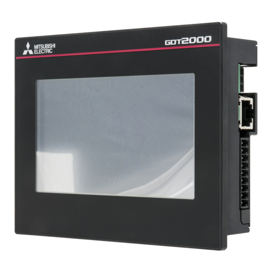
GOT2000 Series Supplementary
Description
(Compliance with the ATEX Directive)
GT2712-STWD
GT2710-VTWD
GT2510-VTWD
GT2508-VTWD
Thank you for purchasing the GOT2000 Series.
Prior to use, please read both this manual and the
detailed manual thoroughly to fully understand the
product.
MODEL
GOT2000-U-ATEX-EK
Model
1D7MQ3
code
IB(NA)-0800551ENG-B(1609)MEE
SAFETY PRECAUTIONS
(Always read these precautions before using this equipment.)
The GOT that complies with the ATEX Directive 94/9/EC of the EU
Directives is in compliance with IECEx Scheme IEC 60079/0/15/31
standards has the Ex marking on its rating plate. To use the ATEX-
compliant GOT in explosive atmospheres, thoroughly read this man-
ual, the GOT2000 Series User's Manual (Hardware), and other rele-
vant manuals introduced therein. Make sure to pay full attention to
safety and handle the product correctly.
The precautions given in this manual are concerned with the ATEX-
compliant GOT to be used specifically in explosive atmospheres.
In this manual, the safety precautions are ranked as "DANGER".
Indicates that incorrect handling may cause
DANGER
hazardous conditions, resulting in death or
serious injury.
Always follow the instructions because they are important to per-
sonal safety.
Please save this manual to make it accessible when required and
always forward it to the end user.
[INSTALLATION PRECAUTIONS]
DANGER
When conducting work (such as installing, operating, or
maintaining the product) in an explosive atmosphere, conform to
the following standards, laws, and regulations. Not doing so
results in death or serious injury.
• Standard IEC 60079-14: Explosive atmospheres - Part 14:
Electrical installations design, selection and erection
• Standard EN 60079-17: Explosive atmospheres - Part 17:
Inspection and maintenance of electrical installations in
hazardous areas
• Regional laws and regulations, etc.
Use both the fittings included with the GOT and separately sold
special fittings (*1) to install the GOT to the control panel.
*1 When purchasing special fittings, consult your local
Mitsubishi representative or branch office.
GOT
Special fitting name
GT2712-STWD
GT25-12FIT-EXS
GT2710-VTWD
GT25-10FIT-EXS
GT2510-VTWD
GT2508-VTWD does not require special fittings.
3. INSTALLING AND REMOVING THE
GOT
3.1 Installing the GOT
Install the GOT in the following procedure.
For the panel cutting dimensions for the GOT, refer to the following.
The following shows an installation example for the horizontal
direction.
For the vertical installation, install the GOT so that the vertical
installation arrow printed on the GOT rear face points
upward.
Step1. Insert the GOT rear face into the panel opening.
GOT
Panel opening
Step2. While positioning a fitting on the mounting hole of the GOT,
tighten a screw within the specified torque range
(0.42 N·m to 0.48 N·m).
Tightening the screw with a torque exceeding the specified
torque range may deform the GOT front panel,
causing the protective sheet to become crinkled.
For GT2508-VTWD (4 fittings)
a
a
a
a
a: Use the Installation fitting (4 fittings)
For GT2710-VTWD, GT2510-VTWD (6 fittings)
a
a
b
a
b
a
a: Use the Installation fitting (4 fittings)
b: Use GT25-10FIT-EXS (separately sold product). (2 fittings)
For GT2712-STWD (8 fittings)
a
b
*1
a
b
a
b
b
a
a: Use the Installation fitting (4 fittings)
b: Use GT25-12FIT-EXS (separately sold product). (4 fittings)
In the middle (b
) of the top, attach a large metal fittings
*1
DANGER
1
2
For GT2508-VTWD (4 fittings)
3
a
a
4
5
6
7
8
a
9
0
a
1
2
a: Use the Installation fitting (4 fittings)
3
For GT2710-VTWD, GT2510-VTWD (6 fittings)
4
a
a
5
6
b
7
8
9
a
0
b
a
a: Use the Installation fitting (4 fittings)
b: Use GT25-10FIT-EXS (separately sold product). (2 fittings)
For GT2712-STWD (8 fittings)
a
*1
b
a
b
a
b
b
a
a: Use the Installation fitting (4 fittings)
b: Use GT25-12FIT-EXS (separately sold product). (4 fittings)
In the middle (b
*1
) of the top, attach a large metal fittings
• Press "b" (GT25-12FIT-EXS, GT25-10FIT-EXS) by hand and
attach it.
Sold separately Protective sheet(*2) is attached on the GOT
surface.
*2 For the Protective sheet sold separately, contact your local
sales office.
GOT
Protective sheet name
GT2712-STWD
GT25-12PSCC-UC
GT2710-VTWD
GT25-10PSCC-UC
GT2510-VTWD
GT25-08PSCC-UC
GT2508-VTWD
If the protective sheet without the hole for the USB
environmental protection cover is attached, position the sheet
from the upper left of the GOT.
3.2 Removing the GOT
Step1. Remove the screws from the GOT.
Remove the fittings from the GOT.
For GT2508-VTWD (4 fittings)
For GT2710-VTWD, GT2510-VTWD (6 fittings)
For GT2712-STWD (8 fittings)
Step2. Remove the GOT from the panel opening.
GOT
Panel opening
DANGER
To attach the protective sheet, attach it from one direction
gradually. Make sure to fit the protective sheet onto the joining
surface closely without leaving any air between them.
Attach the protective sheet with adding additional pressure
sufficiently to the adhesive side of the outer circumference.
To hold adequate strength of the adhesive joining, use the GOT
after a lapse of about 24 hours.
If any of the fittings is out of place, the GOT installed to the
control panel does not comply with the ATEX Directive. (The
GOT cannot be used in explosive atmospheres.)
[PRECAUTIONS
FOR
INSTALLATION,
REMOVAL,
OPERATION, AND MAINTENANCE]
DANGER
The ATEX-compliant GOT is usable in Zone 2 or Zone 22
explosive atmospheres.
• Low mechanical impact: This equipment is to be installed in
an area of low mechanical impact.
• Electrostatic charging: Wipe the front panel with a damp cloth
before turning on the equipment.
• Extension and auxiliary extension interfaces : Extension and
auxiliary extension interfaces cannot be used in explosive
atmospheres.
• Before mounting or demounting, replacing, or wiring the GOT,
make sure that there is no explosive gas or dust around the
product.
• The ambient temperature of the protective enclosure must be
55°C or less.
• Make sure that each interface, the terminal block, an SD card,
and the battery cover are secured firmly into place.
• The USB cable must be clamped appropriately at the USB
interface (Host/Device). (Figure 1 is an example of clamping a
cable at the USB interface (Host).)
Figure 1
• The GOT must be installed in a protective enclosure with the
following protective structure rating.
- IP54 for use in gas atmospheres
- IP6X for use in dust atmospheres
• The protective enclosure cannot be opened while the system
is energized.
• Make sure to turn off the GOT, and then conduct work (such
as wiring or installing the GOT and inserting or removing an
SD card).
• Make sure that the FG terminal of the power supply is
grounded.
• Make sure that the GOT is screwed firmly into place.
• Do not use any damaged equipment.
4. INSTALLING AND REMOVING THE
BATTERY
Install a battery to the GOT before the first startup.
GT27 and GT25 come with a battery in the battery holder. Before
using GT27 and GT25, connect the battery connector to the GOT
connector.
To replace the battery, leave the GOT on for more than 10 minutes
before replacing the battery.Replace the battery within 5 minutes.
The following shows the procedure for installing and removing a
battery.(Described with the GOT rear face facing up.)
4.1 Installing the Battery
4.1.1 Installing the battery to GT2712-STWD, GT2710-
VTWD or GT2510-VTWD
Step1. Make sure that the GOT power is off.
Step2. Install the battery to the GOT rear face.
Open the battery cover as shown below.
Battery cover
Step3. Insert the battery connector to the GOT connector.
Battery cover
Black cable
Red cable
Battery
Connector
Without a battery extension cable
Step4. After installing the battery to the battery holder of the GOT,
close the battery cover until it clicks.
Battery
Battery cover
Connector
Step5. Turn on the GOT.
Step6. Check that the battery condition is normal with the utility.
Manual
The following shows manuals relevant to this product.
Manual name
Manual number (Model code)
GOT2000 Series User's Manual (Hardware)
SH-081194ENG (1D7MJ5)
For detailed manuals and relevant manuals, refer to the Help or the
PDF manuals stored in the DVD-ROM for the screen design
software used.
The latest manuals are also available from MITSUBISHI
ELECTRIC FA Global Website (http://www.MitsubishiElectric.com/
fa/).
© 2016MITSUBISHI ELECTRIC CORPORATION
Before using the GOT
Connect the GOT to the battery.
Refer to the GOT2000 Series User's Manual (Hardware) for the
connection instructions.
For details on the GOT specifications, installing instructions, wiring,
maintenance
and inspection, or checking procedure for the version and the
compatible standard, refer to the GOT2000 Series User's Manual
(Hardware).
1. CONFORMING STANDARDS
The GOT with the Ex marking on its rating plate complies with the
following standards.
- Standard EN 60079-0: Explosive atmospheres - Part 0:
Equipment - General requirements
- Standard EN 60079-15: Explosive atmospheres - Part 15:
Equipment protection by type of protection "n"
- Standard EN 60079-31: Explosive atmospheres - Part 31:
Equipment dust ignition protection by enclosure "t"
2. Ex MARKING
The ATEX-compliant GOT has the Ex marking on its rating plate as
shown below.
|| 3 G Ex nA ||C T5 Gc
|| 3 D Ex tc |||C T100°C Dc
Tamb 0°C to +55°C
TUV 15 ATEX 7585 X
IECEx TUR 15.0030 X
The following shows the meaning of the Ex marking.
(1) II 3G Ex nA IIC T5 Gc
II: Product group (non-mining)
3G: Product category (Zone 2, gases/vapors)
Ex: Explosion proof
nA: Type of protection (Non-sparking equipment)
IIC: Gas atmosphere (Typical gas: hydrogen)
T5: Temperature class (Highest surface temperature: 100°C)
Gc: Equipment protection level (Non-sparking equipment during
normal operation)
(2) II 3D Ex tc IIIC T100°C Dc
II: Product group (non-mining)
3D: Product category (Zone 22, dusts)
Ex: Explosion proof
Tc: Type of protection (Dust ignition protection)
IIIC: Dust atmosphere (Conductive dust)
T100°C: Highest surface temperature 100°C
Dc: Equipment protection level (Dust ignition protection by
enclosure)
(3) Tamb 0°C to +55°C
Operating ambient temperature ranging from 0°C to 55°C
(4) TUV 15 ATEX 7585 X
Certificate number
(5) IECEx TUR 15.0030 X
Certificate number
4.1.2 Installing the battery to GT2508-VTWD
Step1. Make sure that the GOT power is off.
Step2. Install the battery inside the SD card cover on the side of the
GOT.Open the SD card cover as shown in the following fig-
ure.
SD card cover
Step3. Insert the battery connector to the GOT connector.
Connector
SD card cover
Battery
Black cable
Red cable
Step4. After installing the battery to the battery holder of the GOT,
close the SD card cover until it clicks.
Battery
SD card cover
Connector
Step5. Turn on the GOT.
Step6. Check that the battery condition is normal with the utility. For
the details of the battery condition display, refer to the follow-
ing.
Advertisement

Related Manuals for Mitsubishi GOT2000 Series


Summary of Contents for Mitsubishi GOT2000 Series
- Page 1 Use the Installation fitting (4 fittings) Before using the GOT product. Connect the GOT to the battery. For GT2710-VTWD, GT2510-VTWD (6 fittings) Refer to the GOT2000 Series User’s Manual (Hardware) for the MODEL GOT2000-U-ATEX-EK connection instructions. Model For details on the GOT specifications, installing instructions, wiring,...
- Page 2 Step4. Push and close the battery cover until it clicks. Battery cover Warranty Mitsubishi will not be held liable for damage caused by factors found not to be the cause of Mitsubishi; machine damage or lost profits caused by faults in the Mitsubishi products; damage, secondary damage, accident compensation caused by special factors unpredictable by Mitsubishi;...
Need help?
Do you have a question about the GOT2000 Series and is the answer not in the manual?
Questions and answers