Sign In
Upload
Manuals
Brands
Mitsubishi Manuals
Inverter
FR-E 500
Mitsubishi FR-E 500 Manuals
Manuals and User Guides for Mitsubishi FR-E 500. We have
6
Mitsubishi FR-E 500 manuals available for free PDF download: Instruction Manual, Manual, Installation Manual
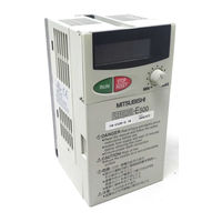
Mitsubishi FR-E 500 Instruction Manual (225 pages)
FR-E 500 Series Transistorized Inverter
Brand:
Mitsubishi
| Category:
Inverter
| Size: 3.5 MB
Table of Contents
Fire Prevention
3
Safety Instructions
3
Table of Contents
7
1 Outline
13
Pre-Operation Information
13
Precautions for Operation
13
Basic Configuration
15
Structure
16
Appearance and Structure
16
Removal and Reinstallation of the
17
Removal and Reinstallation of the Wiring Cover
19
Removal and Reinstallation of the Accessory Cover
20
Reinstallation and Removal of the Control Panel
21
Removal of the Control Panel (FR-PA02- )
22
Front Cover
22
Exploded View
23
2 Installation and Wiring
25
Installation
25
Instructions for Installation
25
Wiring
27
Terminal Connection Diagram
27
Wiring of the Main Circuit
31
Wiring of the Control Circuit
35
Connection to the PU Connector
40
Connection of Stand-Alone Option Units
43
Design Information
46
Other Wiring
47
Power Supply Harmonics
47
Inverter-Generated Noise and Reduction Techniques
48
Leakage Currents and Countermeasures
52
Inverter-Driven 400V Class Motor
53
Peripheral Devices
54
Instructions for Compliance with U.S and Canadian Electrical Codes
58
Instructions for Compliance with the European Standards
59
3 Operation/Control
61
Pre-Operation Information
62
Types of Operation Modes
62
Power on
64
About the Control Panel
65
Names and Functions of the Control Panel (FR-PA02- )
65
MODE Key
65
Monitoring
66
Frequency Setting
67
Parameter Setting Method
67
Operation Mode
69
Help Mode
69
Operation
72
Pre-Operation Checks
72
External Operation Mode (Operation Using the External Frequency Setting Potentiometer and External Start Signal)
73
PU Operation Mode (Operation Using the Control Panel)
74
Combined Operation Mode 1 (Operation Using both External Start Signal and Control Panel)
75
Combined Operation Mode 2
76
4 Parameters
78
Parameter List
78
List of Parameters Classified by Purpose of Use
84
Parameters Recommended to be Set by the User
86
Parameter Function Details
87
Torque Boost (Pr. 0, Pr. 46)
87
Output Frequency Range (Pr. 1, Pr. 2, Pr. 18)
88
Base Frequency, Base Frequency Voltage (Pr. 3, Pr. 19, Pr. 47)
89
Multi-Speed Operation (Pr. 4, Pr. 5, Pr. 6, Pr. 24 to Pr. 27, Pr. 232 to Pr. 239)
90
Acceleration/Deceleration Time (Pr. 7, Pr. 8, Pr. 20, Pr. 21, Pr. 44, Pr. 45)
91
Electronic Overcurrent Protection (Pr. 9, Pr. 48)
93
DC Injection Brake (Pr. 10 to Pr. 12)
94
Starting Frequency (Pr. 13)
95
Load Pattern Selection (Pr. 14)
96
Jog Operation (Pr. 15, Pr. 16)
97
Stall Prevention (Pr. 22, Pr. 23, Pr. 66)
98
Acceleration/Deceleration Pattern (Pr. 29)
100
Regenerative Brake Duty (Pr. 30, Pr. 70)
101
Frequency Jump (Pr. 31 to Pr. 36)
102
Speed Display (Pr. 37)
103
Frequency at 5V (10V) Input (Pr. 38)
104
Frequency at 20Ma Input (Pr. 39)
104
Up-To-Frequency Sensitivity (Pr. 41)
105
Output Frequency Detection (Pr. 42, Pr. 43)
105
Monitor Display (Pr. 52, Pr. 54, Pr. 158)
107
Monitoring Reference (Pr. 55, Pr. 56)
109
Automatic Restart after Instantaneous Power Failure (Pr. 57, Pr. 58)
110
Remote Setting Function Selection (Pr. 59)
112
Shortest Acceleration/Deceleration Mode (Pr. 60 to Pr. 63)
114
Retry Function (Pr. 65, Pr. 67 to Pr. 69)
116
Applied Motor (Pr. 71)
118
PWM Carrier Frequency (Pr. 72, Pr. 240)
119
Voltage Input (Pr. 73)
120
Input Filter Time Constant (Pr. 74)
121
Reset Selection/Disconnected PU Detection/Pu Stop Selection (Pr. 75)
121
Parameter Write Inhibit Selection (Pr. 77)
123
Reverse Rotation Prevention Selection (Pr. 78)
124
Operation Mode Selection (Pr. 79)
125
General-Purpose Magnetic Flux Vector Control Selection (Pr. 80)
128
Offline Auto Tuning Function (Pr. 82 to Pr. 84, Pr. 90, Pr. 96)
130
Computer Link Operation (Pr. 117 to Pr. 124, Pr. 342)
136
Communication Specification
142
Setting Items and Set Data
144
PID Control (Pr. 128 to Pr. 134)
149
Output Current Detection Function (Pr. 150, Pr.151)
157
Zero Current Detection (Pr. 152, Pr.153)
158
Stall Prevention Function and Current Limit Function (Pr. 156)
159
User Group Selection (Pr. 160, Pr. 173 to Pr. 176)
161
Actual Operation Hour Meter Clear (Pr. 171)
163
Input Terminal Function Selection (Pr. 180 to Pr. 183)
163
Output Terminal Function Selection (Pr. 190 to Pr. 192)
165
Cooling Fan Operation Selection (Pr. 244)
166
Slip Compensation (Pr. 245 to Pr. 247)
167
Ground Fault Detection at Start (Pr. 249)
168
(400V Class Does Not Have this Function)
168
Stop Selection (Pr. 250)
169
Output Phase Failure Protection Selection (Pr. 251)
170
Meter (Frequency Meter) Calibration (Pr. 900) (200V Class, 100V Class)
171
Meter (Frequency Meter) Calibration (Pr. 901) (400V Class)
173
(Pr. 902 to Pr. 905)
175
Biases and Gains of the Frequency Setting Voltage (Current)
175
Adjustment Procedure
176
5 Protective Functions
182
Errors (Alarms)
182
Error (Alarm) Definitions
182
To Know the Operating Status at the Occurrence of Alarm
190
Correspondence between Digital and Actual Characters
190
Resetting the Inverter
190
Troubleshooting
191
Motor Remains Stopped
191
Motor Rotates in Opposite Direction
191
Speed Greatly Differs from the Setting
192
Acceleration/Deceleration Is Not Smooth
192
Motor Current Is Large
192
Speed Does Not Increase
192
Speed Varies During Operation
192
Operation Mode Is Not Changed Properly
193
Control Panel Display Is Not Operating
193
POWER Lamp Is Not Lit
193
Parameter Write Cannot be Performed
193
Precautions for Maintenance and Inspection
194
Check Items
194
Periodic Inspection
194
Insulation Resistance Test Using Megger
195
Pressure Test
195
Daily and Periodic Inspection
196
Replacement of Parts
199
Measurement of Main Circuit Voltages, Currents and Powers
204
Frequency Setting
205
6 Specifications
207
Standard Specifications
208
Model Specifications
208
Common Specifications
211
Operation Mode
212
Outline Drawings
213
Appendix
219
Appendix 1 Data Code List
220
Advertisement
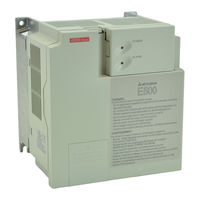
Mitsubishi FR-E 500 Instruction Manual (224 pages)
TRANSISTORIZED INVERTER, HIGH PERFORMANCE & HIGH FUNCTION
Brand:
Mitsubishi
| Category:
Inverter
| Size: 3.36 MB
Table of Contents
Table of Contents
7
Outline
13
Pre-Operation Information
13
Precautions for Operation
13
Basic Configuration
15
Structure
16
Appearance and Structure
16
Removal and Reinstallation of the
17
Removal and Reinstallation of the Wiring Cover
19
Removal and Reinstallation of the Accessory Cover
20
Reinstallation and Removal of the Control Panel
21
Removal of the Control Panel (FR-PA02- )
22
Front Cover
22
Exploded View
23
Installation and Wiring
25
Installation
25
Instructions for Installation
25
Wiring
27
Terminal Connection Diagram
27
Wiring of the Main Circuit
31
Wiring of the Control Circuit
35
Connection to the PU Connector
40
Connection of Stand-Alone Option Units
43
Design Information
46
Other Wiring
47
Power Supply Harmonics
47
Inverter-Generated Noise and Reduction Techniques
48
Leakage Currents and Countermeasures
52
Inverter-Driven 400V Class Motor
53
Peripheral Devices
54
Instructions for Compliance with U.S and Canadian Electrical Codes
58
Instructions for Compliance with the European Standards
59
Operation/Control
61
Pre-Operation Information
62
Types of Operation Modes
62
Power on
64
About the Control Panel
65
Names and Functions of the Control Panel (FR-PA02- )
65
MODE Key
65
Monitoring
66
Frequency Setting
67
Parameter Setting Method
67
Operation Mode
69
Help Mode
69
Operation
72
Pre-Operation Checks
72
External Operation Mode (Operation Using the External Frequency Setting Potentiometer and External Start Signal)
73
PU Operation Mode (Operation Using the Control Panel)
74
Combined Operation Mode 1 (Operation Using both External Start Signal and Control Panel)
75
Combined Operation Mode 2
76
Parameters
77
Parameter List
78
List of Parameters Classified by Purpose of Use
84
Parameters Recommended to be Set by the User
86
Parameter Function Details
87
Torque Boost (Pr. 0, Pr. 46)
87
Output Frequency Range (Pr. 1, Pr. 2, Pr. 18)
88
Base Frequency, Base Frequency Voltage (Pr. 3, Pr. 19, Pr. 47)
89
Multi-Speed Operation (Pr. 4, Pr. 5, Pr. 6, Pr. 24 to Pr. 27, Pr. 232 to Pr. 239)
90
Acceleration/Deceleration Time (Pr. 7, Pr. 8, Pr. 20, Pr. 21, Pr. 44, Pr. 45)
91
Electronic Overcurrent Protection (Pr. 9, Pr. 48)
93
DC Injection Brake (Pr. 10 to Pr. 12)
94
Starting Frequency (Pr. 13)
95
Load Pattern Selection (Pr. 14)
96
Jog Operation (Pr. 15, Pr. 16)
97
Stall Prevention (Pr. 22, Pr. 23, Pr. 66)
98
Acceleration/Deceleration Pattern (Pr. 29)
100
Regenerative Brake Duty (Pr. 30, Pr. 70)
101
Frequency Jump (Pr. 31 to Pr. 36)
102
Speed Display (Pr. 37)
103
Frequency at 5V (10V) Input (Pr. 38)
104
Frequency at 20Ma Input (Pr. 39)
104
Up-To-Frequency Sensitivity (Pr. 41)
105
Output Frequency Detection (Pr. 42, Pr. 43)
105
Monitor Display (Pr. 52, Pr. 54, Pr. 158)
107
Monitoring Reference (Pr. 55, Pr. 56)
109
Automatic Restart after Instantaneous Power Failure (Pr. 57, Pr. 58)
110
Remote Setting Function Selection (Pr. 59)
112
Shortest Acceleration/Deceleration Mode (Pr. 60 to Pr. 63)
114
Retry Function (Pr. 65, Pr. 67 to Pr. 69)
116
Applied Motor (Pr. 71)
118
PWM Carrier Frequency (Pr. 72, Pr. 240)
119
Voltage Input (Pr. 73)
120
Input Filter Time Constant (Pr. 74)
121
Reset Selection/Disconnected PU Detection/Pu Stop Selection (Pr. 75)
121
Parameter Write Inhibit Selection (Pr. 77)
123
Reverse Rotation Prevention Selection (Pr. 78)
124
Operation Mode Selection (Pr. 79)
125
General-Purpose Magnetic Flux Vector Control Selection (Pr. 80)
128
Offline Auto Tuning Function (Pr. 82 to Pr. 84, Pr. 90, Pr. 96)
130
Computer Link Operation (Pr. 117 to Pr. 124, Pr. 342)
136
PID Control (Pr. 128 to Pr. 134)
149
Output Current Detection Function (Pr. 150, Pr.151)
157
Zero Current Detection (Pr. 152, Pr.153)
158
Stall Prevention Function and Current Limit Function (Pr. 156)
159
User Group Selection (Pr. 160, Pr. 173 to Pr. 176)
161
Actual Operation Hour Meter Clear (Pr. 171)
163
Input Terminal Function Selection (Pr. 180 to Pr. 183)
163
Output Terminal Function Selection (Pr. 190 to Pr. 192)
165
Cooling Fan Operation Selection (Pr. 244)
166
Slip Compensation (Pr. 245 to Pr. 247)
167
Ground Fault Detection at Start (Pr. 249)
168
(400V Class Does Not Have this Function)
168
Stop Selection (Pr. 250)
169
Output Phase Failure Protection Selection (Pr. 251)
170
Meter (Frequency Meter) Calibration (Pr. 900) (200V Class, 100V Class)
171
Meter (Frequency Meter) Calibration (Pr. 901) (400V Class)
173
Biases and Gains of the Frequency Setting Voltage (Current)
175
(Pr. 902 to Pr. 905)
175
Protective Functions
182
Errors (Alarms)
182
Error (Alarm) Definitions
182
To Know the Operating Status at the Occurrence of Alarm
190
Correspondence between Digital and Actual Characters
190
Resetting the Inverter
190
Troubleshooting
191
Motor Remains Stopped
191
Motor Rotates in Opposite Direction
191
Speed Greatly Differs from the Setting
192
Acceleration/Deceleration Is Not Smooth
192
Motor Current Is Large
192
Speed Does Not Increase
192
Speed Varies During Operation
192
Operation Mode Is Not Changed Properly
193
Control Panel Display Is Not Operating
193
POWER Lamp Is Not Lit
193
Parameter Write Cannot be Performed
193
Precautions for Maintenance and Inspection
194
Check Items
194
Periodic Inspection
194
Insulation Resistance Test Using Megger
195
Pressure Test
195
Daily and Periodic Inspection
196
Replacement of Parts
199
Measurement of Main Circuit Voltages, Currents and Powers
204
Specifications
208
Standard Specifications
208
Model Specifications
208
Common Specifications
211
Outline Drawings
213
Appendix
219
Appendix 1 Data Code List
220
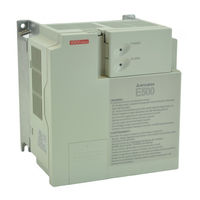
Mitsubishi FR-E 500 Instruction Manual (217 pages)
TRANSISTORIZED INVERTER
Brand:
Mitsubishi
| Category:
Inverter
| Size: 3.03 MB
Table of Contents
Table of Contents
7
Outline
13
Pre-Operation Information
13
Precautions for Operation
13
Basic Configuration
15
Structure
16
Appearance and Structure
16
Removal and Reinstallation of the
17
Removal and Reinstallation of the Wiring Cover
18
Removal and Reinstallation of the Accessory Cover
19
Reinstallation and Removal of the Control Panel
20
Removal of the Operation Panel (FR-PA02- )
22
Front Cover
22
Exploded View
22
Installation and Wiring
24
Installation
24
Instructions for Installation
24
Wiring
26
Terminal Connection Diagram (When Source Logic Is Selected)
26
Wiring of the Main Circuit
30
Wiring of the Control Circuit
35
Connection to the PU Connector
39
Connection of Stand-Alone Option Units
42
Design Information
44
Other Wiring
45
Power Supply Harmonics
45
Inverter-Generated Noise and Reduction Techniques
46
Leakage Currents and Countermeasures
50
Inverter-Driven 400V Class Motor
51
Peripheral Devices
52
Instructions for Compliance with U.S. and Canadian Electrical Codes
56
Instructions for Compliance with the European Standards
57
Operation/Control
59
Pre-Operation Information
60
Types of Operation Modes
60
Power on
62
About the Control Panel
63
Names and Functions of the Control Panel (FR-PA02- )
63
MODE Key
63
Monitoring
64
Frequency Setting
65
Parameter Setting Method
65
Operation Mode
67
Help Mode
67
Operation
69
Pre-Operation Checks
69
External Operation Mode (Operation Using the External Frequency Setting Potentiometer and External Start Signal)
70
PU Operation Mode (Operation Using the Control Panel)
71
Combined Operation Mode 1 (Operation Using both External Start Signal and Control Panel)
72
Combined Operation Mode 2
73
Parameters
75
Parameter List
75
List of Parameters Classified by Purpose of Use
81
Parameters Recommended to be Set by the User
83
Parameter Function Details
84
Torque Boost (Pr. 0, Pr. 46)
84
Output Frequency Range (Pr. 1, Pr. 2, Pr. 18)
85
Base Frequency, Base Frequency Voltage (Pr. 3, Pr. 19, Pr. 47)
86
Multi-Speed Operation
87
(Pr. 4, Pr. 5, Pr. 6, Pr. 24 to Pr. 27, Pr. 232 to Pr. 239)
87
Acceleration/Deceleration Time (Pr. 7, Pr. 8, Pr. 20, Pr. 21, Pr. 44, Pr. 45)
88
Electronic Overcurrent Protection (Pr. 9, Pr. 48)
90
DC Injection Brake (Pr. 10 to Pr. 12)
91
Starting Frequency (Pr. 13)
92
Load Pattern Selection (Pr. 14)
93
Jog Operation (Pr. 15, Pr. 16)
94
Stall Prevention (Pr. 22, Pr. 23, Pr. 66)
95
Acceleration/Deceleration Pattern (Pr. 29)
97
Regenerative Brake Duty (Pr. 30, Pr. 70)
98
Frequency Jump (Pr. 31 to Pr. 36)
99
Speed Display (Pr. 37)
100
Frequency at 5V (10V) Input (Pr. 38)
101
Frequency at 20Ma Input (Pr. 39)
101
Up-To-Frequency Sensitivity (Pr. 41)
102
Output Frequency Detection (Pr. 42, Pr. 43)
103
Monitor Display (Pr. 52, Pr. 158)
104
Monitoring Reference (Pr. 55, Pr. 56)
106
Automatic Restart after Instantaneous Power Failure (Pr. 57, Pr. 58)
107
Remote Setting Function Selection (Pr. 59)
108
Shortest Acceleration/Deceleration Mode (Pr. 60 to Pr. 63)
110
Retry Function (Pr. 65, Pr. 67 to Pr. 69)
111
Applied Motor (Pr. 71)
113
PWM Carrier Frequency (Pr. 72, Pr. 240)
114
Voltage Input (Pr. 73, Pr. 254)
115
Input Filter Time Constant (Pr. 74)
117
Reset Selection/Disconnected PU Detection/Pu Stop Selection (Pr. 75)
117
Parameter Write Inhibit Selection (Pr. 77)
119
Reverse Rotation Prevention Selection (Pr. 78)
120
Operation Mode Selection (Pr. 79)
121
General-Purpose Magnetic Flux Vector Control Selection (Pr. 80)
125
Offline Auto Tuning Function (Pr. 82 to Pr. 84, Pr. 90, Pr. 96)
126
Computer Link Operation (Pr. 117 to Pr. 124, Pr. 338 to Pr. 340, Pr. 342)
132
PID Control (Pr. 128 to Pr. 134)
149
Output Current Detection Function (Pr. 150, Pr. 151)
157
Zero Current Detection (Pr. 152, Pr. 153)
158
Stall Prevention Function and Current Limit Function (Pr. 156)
159
User Group Selection (Pr. 160, Pr. 173 to Pr. 176)
161
Actual Operation Hour Meter Clear (Pr. 171)
163
Input Terminal Function Selection (Pr. 180 to Pr. 183)
163
Output Terminal Function Selection (Pr. 190 to Pr. 192)
165
Cooling Fan Operation Selection (Pr. 244)
166
Slip Compensation (Pr. 245 to Pr. 247)
167
Stop Selection (Pr. 250)
168
Output Phase Failure Protection Selection (Pr. 251)
169
Meter (Frequency Meter) Calibration (Pr. 901)
170
Biases and Gains of the Frequency Setting Voltage (Current)
172
(Pr. 902 to Pr. 905)
172
Protective Functions
179
Errors (Alarms)
179
Error (Alarm) Definitions
179
To Know the Operating Status at the Occurrence of Alarm
187
Correspondence between Digital and Actual Characters
187
Resetting the Inverter
187
Troubleshooting
188
Motor Remains Stopped
188
Motor Rotates in Opposite Direction
188
Speed Greatly Differs from the Setting
189
Acceleration/Deceleration Is Not Smooth
189
Motor Current Is Large
189
Speed Does Not Increase
189
Speed Varies During Operation
189
Operation Mode Is Not Changed Properly
190
Control Panel Display Is Not Operating
190
POWER Lamp Is Not Lit
190
Parameter Write Cannot be Performed
190
Precautions for Maintenance and Inspection
191
Check Items
191
Periodic Inspection
191
Insulation Resistance Test Using Megger
192
Pressure Test
192
Daily and Periodic Inspection
193
Replacement of Parts
196
Measurement of Main Circuit Voltages, Currents and Powers
200
Specifications
202
Standard Specifications
203
Model Specifications
203
Common Specifications
205
Outline Drawings
207
Appendix
209
Appendix 1 Data Code List
210
Appendix 2 When Using the Communicaton Option
214
Advertisement
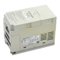
Mitsubishi FR-E 500 Instruction Manual (207 pages)
TRANSISTORIZED INVERTER
Brand:
Mitsubishi
| Category:
Inverter
| Size: 2.46 MB
Table of Contents
Table of Contents
7
Outline
13
Pre-Operation Information
13
Precautions for Operation
13
Basic Configuration
15
Structure
16
Appearance and Structure
16
Functions
16
Removal and Reinstallation of the
17
Removal and Reinstallation of the Wiring Cover
18
Removal and Reinstallation of the Accessory Cover
19
Exploded View
20
Installation and Wiring
22
Installation
22
Instructions for Installation
22
Wiring
24
Terminal Connection Diagram
24
Wiring of the Main Circuit
27
Wiring of the Control Circuit
31
Devicenet Communication Signal Wiring
34
Connection to the PU Connector
39
Connection of Stand-Alone Option Units
42
Design Information
45
Other Wiring
46
Power Supply Harmonics
46
Japanese Harmonic Suppression Guideline
47
Inverter-Generated Noise and Reduction Techniques
50
Leakage Currents and Countermeasures
54
Peripheral Devices
55
Instructions for Compliance with U.S. and Canadian Electrical Codes
59
Operation/Control
60
Inverter Settings
61
Node Address of the Inverter
61
Configuration
63
General Description
63
Set Baud Rate
64
Set Node Address
64
Devicenet I/O Assembly
64
Operation
66
Operation Modes
66
Functions Available in the Operation Modes
66
Input from Devicenet to Inverter
67
Output from Inverter to Devicenet
67
Operation on Alarm Occurrence
68
Inverter Reset
68
Setting Frequency (F) Value
68
Parameter Clear (Pr Clr) Commands
68
Control Input Commands
68
Parameters
70
Parameter List
70
List of Parameters Classified by Purpose of Use
75
Parameters Recommended to be Set by the User
76
Parameter Function Details
77
Torque Boost (Pr. 0, Pr. 46)
77
Output Frequency Range (Pr. 1, Pr. 2, Pr. 18)
78
Base Frequency, Base Frequency Voltage (Pr. 3, Pr. 19, Pr. 47)
79
Multi-Speed Operation (Pr. 4, Pr. 5, Pr. 6, Pr. 24 to Pr. 27, Pr. 232 to Pr. 239)
80
Acceleration/Deceleration Time (Pr. 7, Pr. 8, Pr. 20, Pr. 21, Pr. 44, Pr. 45)
81
Electronic Overcurrent Protection (Pr. 9, Pr. 48)
83
DC Injection Brake (Pr. 10 to Pr. 12)
84
Starting Frequency (Pr. 13)
85
Load Pattern Selection (Pr. 14)
86
Stall Prevention (Pr. 22, Pr. 23, Pr. 66)
87
Acceleration/Deceleration Pattern (Pr. 29)
89
Regenerative Brake Duty (Pr. 30, Pr. 70)
90
Frequency Jump (Pr. 31 to Pr. 36)
91
Speed Display (Pr. 37)
92
Up-To-Frequency Sensitivity (Pr. 41)
93
Output Frequency Detection (Pr. 42, Pr. 43)
93
Monitor Display (Pr. 52)
94
Automatic Restart after Instantaneous Power Failure (Pr. 57, Pr. 58)
96
Shortest Acceleration/Deceleration Mode (Pr. 60 to Pr. 63)
97
Retry Function (Pr. 65, Pr. 67 to Pr. 69)
99
Applied Motor (Pr. 71)
101
PWM Carrier Frequency (Pr. 72, Pr. 240)
102
Reset Selection/Disconnected PU Detection/Pu Stop Selection (Pr. 75)
103
Parameter Write Inhibit Selection (Pr. 77)
105
Reverse Rotation Prevention Selection (Pr. 78)
105
Operation Mode Selection (Pr. 79)
106
General-Purpose Magnetic Flux Vector Control Selection (Pr. 80)
107
Offline Auto Tuning Function (Pr. 82 to Pr. 84, Pr. 90, Pr. 96)
108
Computer Link Operation (Pr. 117 to Pr. 124)
114
Settings for Connection of FR-PU04 (Pr. 145, Pr. 990, Pr. 991)
127
Output Current Detection Function (Pr. 150, Pr. 151)
128
Zero Current Detection (Pr. 152, Pr. 153)
129
Stall Prevention Function and Current Limit Function (Pr. 156)
130
User Group Selection (Pr. 160, Pr. 173 to Pr. 176)
132
Actual Operation Hour Meter Clear (Pr. 171)
133
Input Terminal (Devicenet Input) Function Selection (Pr. 180 to Pr. 183)
133
Output Terminal (Devicenet Input) Function Selection (Pr. 190 to Pr. 192)
135
Cooling Fan Operation Selection (Pr. 244)
136
Slip Compensation (Pr. 245 to Pr. 247)
137
Ground Fault Detection at Start (Pr. 249)
138
Stop Selection (Pr. 250)
138
Devicenet Specific Parameters (Pr. 345 to Pr. 348)
140
Protective Functions
143
Errors (Alarms)
143
Operation at Alarm Occurrence
143
Error (Alarm) Definitions
144
To Know the Operating Status at the Occurrence of Alarm
150
Correspondence between Digital and Actual Characters
150
Resetting the Inverter
150
Troubleshooting
151
Motor Remains Stopped
151
Motor Rotates in Opposite Direction
151
Speed Greatly Differs from the Setting
152
Acceleration/Deceleration Is Not Smooth
152
Motor Current Is Large
152
Speed Does Not Increase
152
Speed Varies During Operation
152
The Operation Mode Does Not Change to the Devicenet Operation Mode
153
The Inverter Does Not Start Even after Entering the Devicenet Operation Mode
153
Parameter Write Cannot be Performed
153
How to Check for Errors Using the Operation Status Indicator LED
154
Inspecting Display on Parameter Unit and Status LED
155
Precautions for Maintenance and Inspection
156
Check Items
156
Periodic Inspection
156
Insulation Resistance Test Using Megger
157
Pressure Test
157
Daily and Periodic Inspection
158
Replacement of Parts
161
Measurement of Main Circuit Voltages, Currents and Powers
163
Specifications
165
Standard Specifications
166
Model Specifications
166
Common Specifications
167
Outline Dimension Drawings
169
Devicenet Specifications
173
Appendix
174
APPENDIX 1 Object Map
175
APPENDIX 2 Electronic Data Sheets (EDS Files)
198
APPENDIX 3 Devicenet Parameters
199
Parameter Data
199
APPENDIX 4 Data Code List
203
Mitsubishi FR-E 500 Manual (167 pages)
Brand:
Mitsubishi
| Category:
Inverter Drive
| Size: 4.44 MB
Table of Contents
Table of Contents
1
System Configuration
2
System Configuration
3
External Devices Selection
9
Communication Settings
10
Setup Items
58
Cable Diagrams
62
Cable Diagram
74
Cable Diagram
84
Cable Diagram
97
Cable Diagram
98
Cable Diagram
119
Cable Diagram
120
Cable Diagram
130
Cable Diagram
137
Cable Diagram
144
Cable Diagram
145
Supported Devices
155
Device Code and Address Code
165
Error Messages
166
Mitsubishi FR-E 500 Installation Manual (28 pages)
Frequency Inverter
Brand:
Mitsubishi
| Category:
Inverter
| Size: 0.32 MB
Table of Contents
About this Manual
2
Table of Contents
3
Safety Instructions
4
1 Introduction
7
General Description
7
2 Specifications
8
Model Specifications FR-E 520S EC (1-Phase Connection)
8
Model Specifications FR-E 540 EC (3-Phase Connection)
9
Model Specifications FR-E 500 EC
10
3 Appearance and Structure
12
Description of the Case
12
4 Wiring
13
Overview
13
Wiring of the Main Circuit
14
Mains, Motor and Ground Terminal Connections
14
Main Circuit Terminals
16
Wiring of the Control Circuit
17
5 Parameter
20
Overview and Setting Ranges
20
6 Protective Functions
24
Error Messages and Remedies
24
7 Dimensions
27
Dimensions of the Frequency Inverters
27
Advertisement
Related Products
Mitsubishi FR-E 540 EC
Mitsubishi FR-E520-0.4KN
Mitsubishi FR-E520-0.2KND
Mitsubishi FR-E520-0.4K-NA
Mitsubishi FR-E520-7.5K-NA
Mitsubishi FR-E540-0.75K-NA
Mitsubishi FR-E510W-0.2K-NA
Mitsubishi FR-E510W-0.1K-NA
Mitsubishi FR-E540-2.2K-NA
Mitsubishi FR-E540-1.5K-NA
Mitsubishi Categories
Air Conditioner
Controller
Projector
Automobile
Engine
More Mitsubishi Manuals
Login
Sign In
OR
Sign in with Facebook
Sign in with Google
Upload manual
Upload from disk
Upload from URL