Sign In
Upload
Manuals
Brands
Mitsubishi Electric Manuals
Amplifier
MELSERVO MR-J2S- A
Mitsubishi Electric MELSERVO MR-J2S- A Manuals
Manuals and User Guides for Mitsubishi Electric MELSERVO MR-J2S- A. We have
1
Mitsubishi Electric MELSERVO MR-J2S- A manual available for free PDF download: Instruction Manual
Mitsubishi Electric MELSERVO MR-J2S- A Instruction Manual (385 pages)
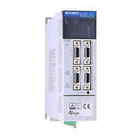
General-Purpose AC Servo General-Purpose Interface SERVO AMPLIFIER
Brand:
Mitsubishi Electric
| Category:
Amplifier
| Size: 6.11 MB
Table of Contents
Safety Instructions
2
Table of Contents
14
1 Functions and Configuration
19
Introduction
19
Function Block Diagram
21
Servo Amplifier Standard Specifications
24
Function List
25
Model Code Definition
26
Combination with Servo Motor
28
Structure
29
Parts Identification
29
Removal and Reinstallation of the
34
Servo System with Auxiliary Equipment
38
2 Installation
44
Environmental Conditions
44
Installation Direction and Clearances
45
Keep out Foreign Materials
46
Cable Stress
47
3 Signals and Wiring
48
Standard Connection Example
49
Position Control Mode
49
Speed Control Mode
53
Torque Control Mode
55
Internal Connection Diagram of Servo Amplifier
57
I/O Signals
58
Connectors and Signal Arrangements
58
Signal Explanations
62
Detailed Description of the Signals
71
Position Control Mode
71
Speed Control Mode
76
Torque Control Mode
78
Position/Speed Control Change Mode
81
Speed/Torque Control Change Mode
83
Torque/Position Control Change Mode
85
Alarm Occurrence Timing Chart
86
Interfaces
87
Common Line
87
Detailed Description of the Interfaces
88
Input Power Supply Circuit
93
Connection Example
93
Terminals
95
Power-On Sequence
96
Connection of Servo Amplifier and Servo Motor
97
Connection Instructions
97
Connection Diagram
97
I/O Terminals
99
Servo Motor with Electromagnetic Brake
101
Grounding
104
Servo Amplifier Terminal Block (TE2) Wiring Method
105
For the Servo Amplifier Produced Later than Jan. 2006
105
For the Servo Amplifier Produced Earlier than Dec. 2005
107
Instructions for the 3M Connector
108
Power Line Circuit of the MR-J2S-11KA to MR-J2S-22KA
109
Connection Example
109
Servo Amplifier Terminals
110
Servo Motor Terminals
111
4 Operation
114
When Switching Power on for the First Time
114
Startup
115
Selection of Control Mode
115
Position Control Mode
115
Speed Control Mode
117
Torque Control Mode
118
Multidrop Communication
119
5 Parameters
120
Parameter List
120
Parameter Write Inhibit
120
Lists
121
Detailed Description
145
Electronic Gear
145
Analog Monitor
149
Using Forward/Reverse Rotation Stroke End to Change the Stopping Pattern
152
Alarm History Clear
152
Position Smoothing
153
6 Display and Operation
154
Display Flowchart
154
Status Display
155
Display Examples
155
Status Display List
156
Changing the Status Display Screen
157
Diagnostic Mode
158
Alarm Mode
160
Parameter Mode
161
External I/O Signal Display
162
Output Signal (DO) Forced Output
165
Test Operation Mode
166
Mode Change
166
Jog Operation
167
Positioning Operation
168
Motor-Less Operation
169
7 General Gain Adjustment
170
Different Adjustment Methods
170
Adjustment on a Single Servo Amplifier
170
Adjustment Using MR Configurator (Servo Configuration Software)
171
Auto Tuning
171
Auto Tuning Mode 1
171
Auto Tuning Mode Operation
173
Adjustment Procedure by Auto Tuning
174
Response Level Setting in Auto Tuning Mode
175
Manual Mode 1 (Simple Manual Adjustment)
176
Operation of Manual Mode 1
176
Adjustment by Manual Mode 1
176
Interpolation Mode
179
Differences in Auto Tuning between MELSERVO-J2 and MELSERVO-J2-Super
180
Response Level Setting
180
Auto Tuning Selection
180
8 Special Adjustment Functions
182
Function Block Diagram
182
Machine Resonance Suppression Filter
182
Adaptive Vibration Suppression Control
184
Low-Pass Filter
185
Gain Changing Function
186
Applications
186
Function Block Diagram
186
Parameters
187
Gain Changing Operation
189
9 Inspection
192
10 Troubleshooting
194
Trouble at Start-Up
194
Position Control Mode
194
Position Control Mode Troubleshooting
194
Speed Control Mode
197
Torque Control Mode
198
When Alarm or Warning Has Occurred
199
Alarms and Warning List
199
Remedies for Alarms
200
Remedies for Warnings
206
11 Outline Dimension Drawings
208
Servo Amplifiers
208
Connectors
215
12 Characteristics
218
Overload Protection Characteristics
218
Power Supply Equipment Capacity and Generated Loss
219
Dynamic Brake Characteristics
222
Encoder Cable Flexing Life
224
Inrush Currents at Power-On of Main Circuit and Control Circuit
225
13 Options and Auxiliary Equipment
226
Options
226
Regenerative Brake Options
226
Brake Unit
235
Power Regeneration Converter
237
External Dynamic Brake
240
Cables and Connectors
243
Junction Terminal Block (MR-TB20)
251
Maintenance Junction Card (MR-J2CN3TM)
253
Battery (MR-BAT, A6BAT)
254
MR Configurator (Servo Configurations Software)
255
Power Regeneration Common Converter
257
Heat Sink Outside Mounting Attachment (MR-JACN)
261
Auxiliary Equipment
264
Recommended Wires
264
No-Fuse Breakers, Fuses, Magnetic Contactors
267
Power Factor Improving Reactors
267
Power Factor Improving DC Reactors
268
Relays
269
Surge Absorbers
269
Noise Reduction Techniques
269
Leakage Current Breaker
275
EMC Filter
277
Setting Potentiometers for Analog Inputs
279
14 Communication Functions
280
Configuration
280
RS-232C Configuration
281
Communication Specifications
282
Communication Overview
282
Parameter Setting
283
Protocol
284
Character Codes
286
Error Codes
287
Checksum
287
Time-Out Operation
288
Retry Operation
288
Initialization
289
Communication Procedure Example
289
Command and Data No. List
290
Read Commands
290
Write Commands
291
Detailed Explanations of Commands
293
Data Processing
293
Status Display
295
Parameter
296
External I/O Pin Statuses (DIO Diagnosis)
298
Disable/Enable of External I/O Signals (DIO)
299
External Input Signal ON/OFF (Test Operation)
300
Test Operation Mode
301
Output Signal Pin ON/OFF Output Signal (DO) Forced Output
303
Alarm History
304
Current Alarm
305
Other Commands
306
15 Absolute Position Detection System
308
Outline
308
Features
308
Restrictions
308
Specifications
309
Battery Installation Procedure
310
Standard Connection Diagram
311
Signal Explanation
312
Startup Procedure
313
Absolute Position Data Transfer Protocol
314
Data Transfer Procedure
314
Transfer Method
315
Home Position Setting
324
Use of Servo Motor with Electromagnetic Brake
326
How to Process the Absolute Position Data at Detection of Stroke End
327
Examples of Use
328
Melsec-A1S (A1Sd71)
328
Confirmation of Absolute Position Detection Data
369
Absolute Position Data Transfer Errors
370
Corrective Actions
370
Error Resetting Conditions
372
Appendix
374
App 1. Signal Arrangement Recording Sheets
374
App 2. Status Display Block Diagram
375
App 3. Combination of Servo Amplifier and Servo Motor
376
Advertisement
Advertisement
Related Products
Mitsubishi Electric MR-J2S-*A
Mitsubishi Electric MR-J2S-CP
Mitsubishi Electric MR-J2S-20CP1
Mitsubishi Electric MR-J2S-350CL
Mitsubishi Electric MR-J2S-10B
Mitsubishi Electric MR-J2S-200B
Mitsubishi Electric MR-J2S-350B
Mitsubishi Electric MR-J2S-10CP-S084
Mitsubishi Electric MR-J2S-20CP1-S084 1
Mitsubishi Electric MR-J2S-700A4/B4
Mitsubishi Electric Categories
Air Conditioner
Controller
Projector
Inverter
Heat Pump
More Mitsubishi Electric Manuals
Login
Sign In
OR
Sign in with Facebook
Sign in with Google
Upload manual
Upload from disk
Upload from URL