Sign In
Upload
Manuals
Brands
Mircom Manuals
Control Panel
FA-1000 SERIES
Mircom FA-1000 SERIES Manuals
Manuals and User Guides for Mircom FA-1000 SERIES. We have
3
Mircom FA-1000 SERIES manuals available for free PDF download: Installation And Operation Manual, Installation Instructions
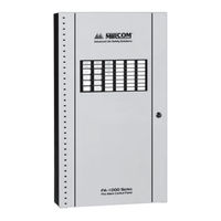
Mircom FA-1000 SERIES Installation And Operation Manual (88 pages)
Microprocessor-Based Fire Alarm Control Panel
Brand:
Mircom
| Category:
Control Panel
| Size: 6 MB
Table of Contents
Table of Contents
3
1 Introduction
9
About this Manual
9
About the FA-1000
9
Overall Features
9
Controls and Indicators
9
Contact Us
10
General Inquiries
10
Customer Service
10
Technical Support
10
Website
10
2 System Components
11
Chassis
11
Circuit Adder Modules
12
Auxiliary Models
12
Enclosures
12
Flush Trim Rings
13
Batteries
13
Remote Annunciators
14
FA-1000 Fire Alarm Control Panel Kits
14
FA-1000 Accessories
14
Maximum Number of Circuit Adder Modules that May be Installed
14
3 Mechanical Installation and Dimensions
16
BB-1024 Installation
16
Figure 1 BB-1024 Flush or Surface Enclosure Installation and Dimensions
16
BB-1072 Installation
17
Figure 2 BB-1072 Flush or Surface Enclosure Installation and Dimensions
17
BBX-1024DS and BBX-1024DSR Mechanical Installation
18
Figure 3 BBX-1024DS and BBX-1024DSR Installation Instructions and Dimensions
18
Main Chassis Installation
19
Figure 4 Main Chassis Installation
19
Main and Expander Chassis Installation
20
Figure 5 Expander Chassis Installation
20
4 Module Mounting Locations
21
BB-1024 and BB-1072 Main Chassis Mounting Locations
22
Figure 6 BB-1024 and BB-1072 Main Chassis Mounting Locations
22
BB-1072 Expansion Chassis Mounting Locations
23
Figure 7 BB-1072 Expansion Chassis Mounting Locations
23
Circuit Adder Mounting Details
24
Figure 8 Circuit Adder Mounting Details
24
5 Module Settings
25
Main Fire Alarm Module
25
Jumpers
25
Figure 9 Main Fire Alarm Module
25
Table 1 Main Fire Alarm Module Circuit Details
25
MCC-1024-6, MCC-1024-12 Main Display Module
26
Figure 10 Main Display Module (MCC-1024-6, MCC-1024-12)
26
Connectors
27
Figure 11 Main Display Module (MCC-1024-6S, MCC-1024-12S)
27
Adder Display Module
28
Connectors
28
Figure 12 Adder Display Module (Part of Expander Chassis)
28
DM-1008A Detection Adder Module
29
Jumpers
29
Figure 13 Detection Adder Module (Model DM-1008A)
29
SGM-1004A Signal Adder Module
30
Jumpers
30
Components
30
Figure 14 Signal Adder Module (Model SGM-1004A)
30
Operation
31
Jumpers for the Bell Cut Mode
31
RM-1008A Relay Adder Module
32
Figure 15 Relay Adder Module (Model RM-1008A)
32
UDACT-300A Digital Communicator Module
33
Figure 16 Digital Communicator Module (Model UDACT-300A)
33
Table 2 Cable Connectors and Miscellaneous
33
Table 3 UDACT-300A List of Leds and Their Functions
33
Figure 17 Polarity Reversal and City Tie Module (Model PR-300)
34
Table 4 Jumpers
34
Jumper and Connector
35
6 Field Wiring
36
Main Fire Alarm Module Terminal Connections
36
Table 5 Settings Permitted in CAN/ULCS527
36
Figure 18 Main Fire Alarm Module Terminal Connections
37
Figure 19 Main Fire Alarm Module Terminal Connections (Continued)
38
Detection Module (DM-1008A) Terminal Connections
39
Figure 20 Detection Module (DM-1008A) Terminal Connections
39
Signal Module (SGM-1004A) Terminal Connections
40
Figure 21 Signal Module (SGM-1004A) Terminal Connections
40
Relay Module (RM-1008A) Terminal Connections
41
Figure 22 Relay Module Terminal Connections
41
UDACT-300A Main Board Terminal Connections
42
Figure 23 UDACT-300A Terminal Connections
42
PR-300 Polarity Reversal and City Tie Module Terminal Connections
43
Figure 24 Polarity Reversal and City Tie Module Terminal Connections
43
Power Supply Connections
44
Figure 25 Power Supply Connections
44
Connecting to a DCS Surguard Receiver
45
Figure 26 Connecting an FA-1000 FACP to a DCS Surguard System Receiver
45
Wiring Tables and Information
46
Table 6 Wiring Table for Input Circuits
46
Table 7 Wiring Table for Indicating Circuits
46
7 System Checkout
47
Before Turning the Power on
47
Power-Up Procedure
47
Troubleshooting
47
8 Indicators, Controls, and Operation
49
Paper Labels for Buttons and Indicators
49
Figure 27 Indicators and Control Location
49
Common Indicators
50
Buzzer
50
Ac on Led
50
Common Alarm LED
50
Common Supervisory LED
50
Common Trouble LED
50
Remote Failure LED
50
Fire Drill LED
50
Automatic Alarm Signal Cancel LED (Acknowledge)
50
General Alarm LED
51
Configuration / Test Mode LED
51
Auxiliary Disconnect LED
51
Signal Silence LED
51
Battery/Charger Trouble LED
51
Ground Fault LED
51
CPU Fault LED
51
Common Controls
52
System Reset Button (White)
52
Signal Silence Button (Blue)
52
Fire Drill Button (Orange)
52
Automatic Alarm Signal Cancel Button (Yellow)
52
General Alarm Button (Red)
52
Auxiliary Disconnect Button (Orange)
52
Lamp Test Button (Orange)
52
Alm/Sup/Tbl/Bldg Audible Sil Button (Blue)
53
Circuit Status Indicators
53
Alarm Circuit Indicators
53
Supervisory Circuit Indicators
53
Property and Building Safety Circuit Indicators
53
Trouble-Only Circuit Indicators
54
Signal Circuit Indicators
54
Relay Circuit Indicators
54
Circuit (Zone) Disconnect Switches
54
Single Stage Operation
54
Two Stage Operation
55
Circuit Types
56
Initiating (Detection) Circuit Types
57
Table 8 Initiating (Detection) Circuit Types
57
Indicating (Signal) Circuit Types
58
Evacuation Codes
58
Table 9 Indicating (Signal) Circuit Types
58
Figure 28 Evacuation Codes
59
9 System Configuration
60
Introduction to Configuration
60
Table 10 Settings Permitted in UL864
60
Table 11 Settings Permitted in CAN/ULCS527
60
Three Buttons and LED Indicators Are Used in Configuration Mode
61
Figure 29 Configuration Indicators and Controls
61
Configuration DIP Switch Functions
62
Table 12 Configuration DIP Switch Functions
62
Entering Configuration Mode
63
Exiting Configuration Mode
64
Factory Default Configuration
64
Restore to Default/Resize (Class a or B)
64
Class B (Style B) Restore Defaults
65
Class a (Style D) Restore Defaults
65
Resize System (Set Circuit Adder Module Number and Type)
65
Configuration Features
66
Table 13 Configuration Features
66
Configuring Initiating and Indicating Circuits
68
Configuring Circuit Correlations
69
Table 14 Configuring Initiating and Indicating Circuits
69
Correlation by Input Circuit
70
Correlation by Output Circuit
70
Display Configuration
71
10 Walk Test Operation
72
11 Appendix A: Compatible Receivers
73
12 Appendix B: RA-1000 Remote Annunciator Panels
74
RA-1000 Series
74
Models
74
Enclosures
74
13 Appendix C: Specifications
75
MCC-1024-6[SA] and MCC-1024-6ADS Specifications
75
Table 15 MCC-1024-6[SA] and MCC-1024-6ADS Specifications
75
MCC-1024-12SA and MCC-1024-12ADS Specifications
77
Table 16 MCC-1024-12[SA] and MCC-1024-12ADS Specifications
77
FA-1000 Expander Chassis and System Modules
78
Table 17 FA-1000 Expander Chassis and System Modules
78
14 Appendix D: Power Supply and Battery Calculations
80
15 Warranty & Warning Information
81
Advertisement
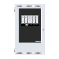
Mircom FA-1000 SERIES Installation And Operation Manual (72 pages)
Microprocessor-Based Fire Alarm Control Panel
Brand:
Mircom
| Category:
Control Panel
| Size: 3 MB
Table of Contents
Table of Contents
3
Introduction
7
About this Manual
7
About the FA-1000
7
Contact Us
8
System Components
9
Chassis
9
Circuit Adder Modules
9
Auxiliary Models
9
Enclosures
10
Flush Trim Rings
10
Batteries
10
Remote Annunciators
10
FA-1000 Fire Alarm Control Panel Kits
11
FA-1000 Accessories
11
Maximum Number of Circuit Adder Modules that May be Installed
11
Mechanical Installation and Dimensions
12
Figure 1 BB-1024 Flush or Surface Enclosure Installation and Dimensions
12
Figure 2 BB-1072 Flush or Surface Enclosure Installation and Dimensions
13
Figure 3 Main Chassis Installation
14
Main Chassis Installation
14
Figure 4 Expander Chassis Installation
15
Main and Expander Chassis Installation
15
Module Mounting Locations
16
Figure 5 BB-1024 and BB-1072 Main Chassis Mounting Locations
16
Figure 6 BB-1072 Expansion Chassis Mounting Locations
17
Figure 7 Circuit Adder Mounting Details
18
Module Settings
19
Figure 8 Main Fire Alarm Module
19
Figure 9 Main Display Module (MCC-1024-6, MCC-1024-12)
20
Figure 10 Main Display Module (MCC-1024-6S, MCC-1024-12S)
21
Figure 11 Adder Display Module (Part of Expander Chassis)
21
Figure 12 Detection Adder Module (Model DM-1008A)
22
Figure 13 Signal Adder Module (Model SGM-1004A)
23
Figure 14 Relay Adder Module (Model RM-1008A)
24
Figure 15 Digital Communicator Module (Model UDACT-300A)
25
Table 1 Cable Connectors and Miscellaneous
25
Table 2 UDACT-300A List of Leds and Their Functions
25
Figure 16 Polarity Reversal and City Tie Module (Model PR-300)
26
Table 3 UDACT-300A List of Jumpers for Operation and Configuration
26
Field Wiring
27
Main Fire Alarm Module Terminal Connections
27
Figure 17 Main Fire Alarm Module Terminal Connections
27
Figure 18 Main Fire Alarm Module Terminal Connections (Continued)
28
Detection Module (DM-1008A) Terminal Connections
29
Figure 19 Detection Module (DM-1008A) Terminal Connections
29
Signal Module (SGM-1004A) Terminal Connections
30
Figure 20 Signal Module (SGM-1004A) Terminal Connections
30
Relay Module (RM-1008A) Terminal Connections
31
Figure 21 Relay Module Terminal Connections
31
UDACT-300A Main Board Terminal Connections
32
Figure 22 UDACT-300A Terminal Connections
32
Polarity Reversal and City Tie Module (Model PR-300) Terminal Connections
33
Figure 23 Polarity Reversal and City Tie Module Terminal Connections
33
Power Supply Connections
34
Figure 24 Power Supply Connections
34
Wiring Tables and Information
35
Table 4 Wiring Table for Initiating Circuits
35
Table 5 Wiring Table for Indicating Circuits
35
System Checkout
36
Before Turning the Power on
36
Power-Up Procedure
36
Troubleshooting
37
Indicators, Controls, and Operation
38
Figure 25 Indicators and Control Location
38
Common Indicators
39
Common Controls
40
Circuit Status Indicators
41
Circuit (Zone) Disconnect Switches
42
Single Stage Operation
43
Two Stage Operation
43
Circuit Types
44
Figure 26 Evacuation Codes
45
System Configuration
46
Introduction to Configuration
46
Figure 27 Configuration Indicators and Controls
46
Table 6 Configuration DIP Switch Functions
47
Entering Configuration Mode
48
Exiting Configuration Mode
48
Factory Default Configuration
49
Restore to Default/Resize (Class a or B)
49
Resize System (Set Circuit Adder Module Number and Type)
50
Configuration Features
50
Configuring Initiating and Indicating Circuits
51
Configuring Circuit Correlations
52
Display Configuration
54
Walk Test Operation
54
Appendix A: RA-1000 Remote Annunciator Panels
55
RA-1000 Series
55
Appendix B: Device Compatibility List
56
FA-1000 Series UL Listed Two-Wire Smoke Detectors
56
FA-1000 Series UL Listed Compatible Four-Wire Smoke Detectors
59
FA-1000 Series UL Listed Compatible Signaling Devices
60
FA-1000 Series ULC Listed Compatible Hardwire Smoke Detectors
61
Appendix C: Module Specifications and Features
63
Appendix D: Power Supply and Battery Calculations
64
Warranty and Warning Information
65
System Users
66
Telephone Lines
66
Component Failure
67
Limited Warranty
67
Out of Warranty Repairs
68
Mircom FA-1000 SERIES Installation Instructions (4 pages)
Addendum for Fire Alarm
Brand:
Mircom
| Category:
Fire Alarms
| Size: 0 MB
Advertisement
Advertisement
Related Products
Mircom FA-101U
Mircom FA-1008KA
Mircom FA-1008KUA
Mircom FA-103
Mircom FA-106
Mircom FA-103R
Mircom FA-106R
Mircom FA-1025T
Mircom FA-300-6L Series
Mircom FA-301-8LDW
Mircom Categories
Control Panel
Intercom System
Fire Alarms
Security System
Controller
More Mircom Manuals
Login
Sign In
OR
Sign in with Facebook
Sign in with Google
Upload manual
Upload from disk
Upload from URL