Sign In
Upload
Manuals
Brands
Keysight Manuals
Extender
E8257D/67D
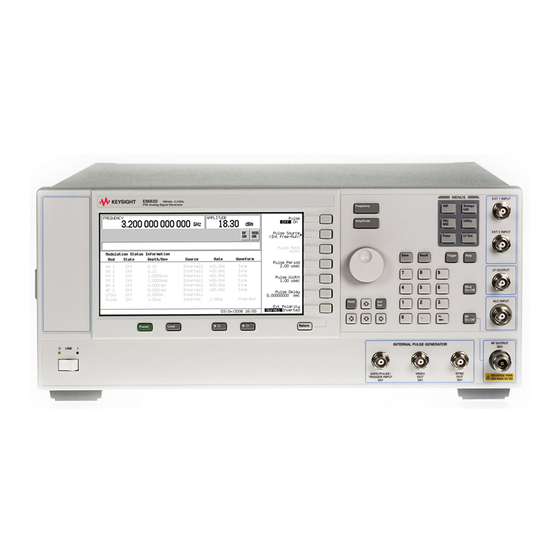
Keysight E8257D/67D Manuals
Manuals and User Guides for Keysight E8257D/67D. We have
1
Keysight E8257D/67D manual available for free PDF download: Service Manual
Keysight E8257D/67D Service Manual (344 pages)
X-Series
Brand:
Keysight
| Category:
Extender
| Size: 11 MB
Table of Contents
Table of Contents
3
Troubleshooting
15
Electrostatic Discharge (ESD) Information
15
Handling of Electronic Components and ESD
16
Getting Started with Troubleshooting
16
Running Self-Test
16
A18 CPU Turn-On Test
17
Failure Symptoms
17
A2 Display Not Functioning or A2 Display Not Functioning after Turn-On
17
A18 CPU Fails to Complete the Turn-On Check
17
Checking the A18 CPU Voltages
18
Verifying the A18 CPU Turn-On Sequence
18
No Instrument Control from the Front Panel
18
Error Messages
18
CPU Data Backup
19
Self-Test Failures and Related Troubleshooting
20
Troubleshooting Assembly-Level Problems
24
Front-Panel Display Assembly Troubleshooting
24
Power Supply Troubleshooting
28
Option 008/009 Troubleshooting
42
Self-Tests 1Xx for the A13 I/Q Multiplexer
43
Self-Tests 2Xx: A5 Sampler Self-Test Errors
45
Self-Tests 3Xx: A7 Reference (Standard) Self-Test Errors (for Instruments with Serial Prefixes < US4805/MY4805)
47
Self-Tests 4Xx: A8 Output Self-Test Errors (E8267D Only)
48
Self-Tests 6Xx: A9 YIG Driver Self-Test Errors
51
Self-Tests 7Xx: A6 Frac-N Self-Test Errors
53
Self-Tests 7Xx: A45 Frac-N Self-Test Errors (Option UNY)
55
Self-Tests 9Xx: A10 ALC Self-Test Errors
56
Self-Tests 10Xx: A7 Reference (Option UNR/UNX and Instruments with Serial Prefixes >= US4805/MY4805) Self-Test Errors
58
Self-Tests 11Xx: A18 CPU Self-Test Errors
59
Self-Tests 12Xx: A26 MID Self-Test Errors (E8257D)
60
Self-Tests 12Xx: A26 MID Self-Test Errors (E8267D)
64
Self-Tests 13Xx: A11 Analog/Pulse Modulation Generator Self-Test Errors
68
Self-Tests 16Xx for the A14 Baseband Generator (Option 601/602)
70
Self-Tests 22Xx: A8 Output Self-Test Errors
72
Self-Tests 24Xx: A38 Lowband Filter Self-Test Errors
73
Self-Tests 25Xx: A43 Amp Filter Self-Test Errors
74
Self-Tests 26Xx: A8 Output Self-Test Errors
76
Self-Tests 27Xx: A46 Offset Loop Self-Test Errors (Option UNY)
77
Self-Tests 28Xx: A8 Vector Output Self-Test Errors
77
Troubleshooting Unlocks
78
508 A6 Frac-N Loop Unlock
78
512 A7 Reference Unlock
79
513 1 Ghz out of Lock
79
514 Reference Oven Cold
79
515 10 Mhz Signal Bad
79
520 Sampler Unlocked
79
521 YO Loop Unlocked
80
625 Internal Pulse Generator Unlock
80
626 Internal Mod Source Unlock
80
Troubleshooting Unlevels
81
Troubleshoot and Correct any Unlock Problems before Troubleshooting Unleveled Problems
81
Troubleshooting Adjustment Problems
86
Troubleshooting ADC Adjustment Failures
88
Troubleshooting Performance Test Problems
88
Troubleshooting the RF Path
89
Troubleshooting RF Power Levels
89
ALC and RF Problems
90
Troubleshooting Pulse Modulation
91
Troubleshooting AT1 Attenuator
91
Troubleshooting Harmonic Spurious
92
20 Ghz Models
93
32 Ghz and 44 Ghz Models Only
94
40 Ghz Models Only
94
50 And 67 Ghz Models Only
95
Troubleshooting Non-Harmonic Spurious
95
Troubleshooting Option UNR/UNX/UNY and Instruments with Serial Prefixes >= US4805/MY4805 Phase Noise
96
Overall Description
97
A18 Cpu
97
A19 Power Supply
97
Input/Output Interface
97
Frequency Generation
98
Reference/Synthesis Loop Description
105
A5 Sampler (CW Mode Only)
106
A6 Frac-N
106
A7 Reference
107
A9 YIG Driver
107
A28 YIG Oscillator (YO)
108
A29 20 Ghz Doubler
108
A38 Switch Filter and A43 Lowband Amp Filter (Option 1EH)
108
Reference/Synthesis Loop
108
A28 YIG Oscillator (YO)
110
A12 <3.2 Ghz Fast Pulse Modulator (Option UNW)
111
A6 Frac-N
111
A8 Output
111
A23 Lowband Coupler/Detector, A24 Highband Coupler, and A25 High Band Detector
112
A27 40 Ghz Doubler (Analog 40 Ghz Models and Vector 44 Ghz Models)
112
A29 20 Ghz Doubler
112
A30 Modulation Filter
112
A6 Frac–N
115
A29 20 Ghz Doubler
116
Approximate Device Gains and Losses
117
RF Path Description (Frequency Generation, Level Control, and Modulation)
110
Vector Low Band RF Path
124
Self–Test Overview
125
Contacting Agilent Technologies
126
Keysight Sales and Service Offices
128
Ordering Information
129
Assemblies
131
Assemblies from the Inside Front Panel View
135
Assemblies from a Top View (E8257D Option 520/540 and E8663D)
137
Assemblies from a Microcircuit Deck View (E8257D Option 520/540 and E8663D)
142
Assemblies from a Bottom View (E8257D and E8663D)
145
A18BT1 Lithium Battery
147
Hardware
163
Front Panel View
164
Disassembled Front Panel View
166
Disassembled Rear Panel View
168
Disassembled A32 10 Mhz Crystal Oscillator (Option UNR/UNX/UNY and Instruments with Serial Prefixes >= US4805/MY4805)
171
Disassembled AT1 90Db/115Db Attenuator View (Option 1E1)
172
Disassembled A24 50Ghz Highband Coupler and A25B Highband Detector Bias Board
175
Disassembled A24 67Ghz Highband Coupler and A25B Highband Detector Bias Board
176
Microcircuit Interface Deck Top View
177
Main Chassis and MID Bottom View
178
MM RF Output Connector (Option 567 Only)
181
MM RF Output Connector
182
APC 3.5 RF Output Connector (Option 520 Only)
183
Type- N RF Output Connector (Option 1ED Models Only)
184
Main Chassis with Inside Cover and Right- Side Support Wall
185
Outer and Inner Instrument Covers and Associated Parts
186
Miscellaneous
187
Electrostatic Discharge (ESD) Protective Supplies
188
Abbreviations Used in Part Descriptions
189
Before You Replace an Assembly
191
Outer Instrument Cover
194
Inner Instrument Cover
196
Front Panel
198
Replacement Procedure
199
A1 Keyboard
201
A2 Display
204
A2DS1 Display Backlight (Serial Number Prefix < US/MY5XXX3XXX Only)
207
A3 Power Switch
209
A4 Inverter (Serial Number Prefix < US/MY5XXX3XXX Only)
212
A5 Sampler, A6 Frac–N, A7 Reference (Standard and Option UNR/UNX/UNY), A8 Output A45 Frac- N and A46 Offset
213
A9 YIG Driver
214
Tools Required
216
A11 Pulse/Analog Modulation Generator
218
A12 Pulse Modulator Board
220
A13 I/Q MUX (E8267D Standard or with Option 015) (Serial Prefixes <US4722/MY4722)
222
A13 I/Q MUX (E8267D Standard or with Option H16/016) (Serial Prefixes >=US4722/MY4722)
224
A14 Baseband Generator (E8267D Only)
226
A17 Baseband Generator Interface (E8267D Only)
228
Tools Required
230
A18Bt1
232
A19 Power Supply
234
A20 SMI (Source Module Interface)
236
A21 Rear–Panel Interface
238
A22 Line Module
240
A23 Lowband Coupler/Detector
242
A24 20 Ghz Highband Coupler (Options 503, 509, 520, and 521)
244
A24 40 Ghz Highband Coupler (Option 540)
248
A24 50 Ghz Highband Coupler (Options 532 and 544)
250
A24 67 Ghz Highband Coupler (Options 550 and 567)
252
A25 20 Ghz Highband Detector (Options 503, 509, 520, & 521)
254
A25 40 Ghz Highband Detector (Option 540)
256
A25 50 Ghz Highband Detector (Options 532 and 544)
257
A25 67 Ghz Highband Detector (Options 550 and 567)
258
A25B Highband Detector Bias Board
260
A26 MID (Microcircuit Interface Deck)
262
A27 40 Ghz Doubler (Option 540)
264
A27 40 Ghz Doubler (Options 532 and 544 Only)
266
A28 YIG Oscillator
268
A29 20 Ghz Doubler
270
A30 Modulation Filter (Standard and Option 1EA/1EU)
272
A31 Motherboard (E8257D & E8663D)
274
A31 Motherboard (E8267D)
276
A32 10 Mhz Crystal Oscillator
278
A33 6Db PAD (Options 503, 509, 520, and 521)
280
A33 10Db PAD (Options 532 and 544)
282
Rear Panel (Standard)
284
Replacement Procedure
285
Rear Panel (Option 1EM)
286
Replacement Procedure
287
A34 Internal Hard Drive (E8267D Only - Discontinued)
289
A35 3–20 Ghz I/Q Modulator (E8267D Only - Standard or with Option 015)
290
A35 3–20 Ghz I/Q Modulator (E8267D Only - Standard or with Option H16/016) (Serial Prefixes US4722/MY4722)
292
A36 Quadraplier (Options 550 and 567)
294
A37 Upconverter (E8267D Only)
296
A38 Lowband Switch Filter
298
A39 Directional Sweep Coupler
300
A40 Compact Flash Drive Assembly
302
A41 Flash Drive Door Assembly
304
A42 20 Ghz Power Amp (Option 521)
306
A43 Lowband Amp Filter
308
A44 Scan Modulation Bias Adapter (E8257D- 520 and E8663D Only)
310
AT1 90 Db Attenuator
312
AT1 115 Db Attenuator
314
AT1 90 Db Attenuator (Option 1EM)
316
AT1 115 Db Attenuator (Option 1EM)
318
Tools Required
320
Post–Repair Procedures Matrix
324
CPU Configuration
336
General Safety Considerations
339
Lithium Battery Disposal
340
Advertisement
Advertisement
Related Products
Keysight E8663D
Keysight E8257D Option H1K
Keysight E8251-60690
Keysight E8251-60990
Keysight E8251-60380
Keysight E8251-60386
Keysight E8251-60396
Keysight E8257D PSG Microwave
Keysight E82 7C Series
Keysight E8267D PSG Microwave
Keysight Categories
Measuring Instruments
Test Equipment
Multimeter
Portable Generator
Power Supply
More Keysight Manuals
Login
Sign In
OR
Sign in with Facebook
Sign in with Google
Upload manual
Upload from disk
Upload from URL