Sign In
Upload
Manuals
Brands
JLG Manuals
Lifting Systems
2032ES
JLG 2032ES Manuals
Manuals and User Guides for JLG 2032ES. We have
3
JLG 2032ES manuals available for free PDF download: Service Maintenance Manual, Operation And Safety Manual
JLG 2032ES Service Maintenance Manual (174 pages)
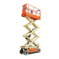
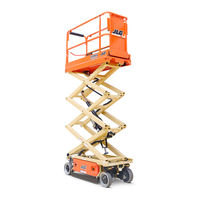
Electric Scissor Lift
Brand:
JLG
| Category:
Lifting Systems
| Size: 9.17 MB
Table of Contents
Introduction - Maintenance Safety Precautions Revision Log
5
Section A. Introduction - Maintenance Safety Precautions
3
General
3
Hydraulic System Safety
3
Maintenance
3
Table of Contents
5
Section 1. Specifications
13
MACHINE Specifications
13
Capacities
14
Fluid Capacities
14
Batteries
15
Battery Charger
15
Motors
15
Tires
15
Lift Speed (no Load in Platform)
16
Travel Speed
16
Model Dimensions
17
Torque Requirements
18
Lubrication
18
Hydraulic Oil
18
Pressure Settings
19
Limit Switches
19
High Drive Speed Cutout
19
Tilt Alarm
19
Cylinder Specifications
20
Major Component Weights
20
Critical Stability Weights
20
Torque Charts
21
Torque Chart - Sheet 2 of 5 - (SAE Fasteners)
22
Torque Chart - Sheet 3 of 5 - (SAE Fasteners)
23
Torque Chart - Sheet 4 of 5 - (METRIC Fasteners)
24
Torque Chart - Sheet 5 of 5 - (METRIC Fasteners)
25
Section 2 - General
27
Machine Preparation, Inspection, and Maintenance
27
Annual Machine Inspection
27
General
27
Pre-Delivery Inspection and Frequent Inspection
27
Pre-Start Inspection
27
Preparation, Inspection, and Maintenance
27
Preventative Maintenance
27
Service and Guidelines
28
Cleanliness
28
Components Removal and Installation
28
General
28
Safety and Workmanship
28
Battery
29
Bearings
29
Bolt Usage and Torque Application
29
Component Disassembly and Reassembly
29
Gaskets
29
Hydraulic Lines and Electrical Wiring
29
Hydraulic System
29
Lubrication
29
Lubrication and Servicing
29
Pressure-Fit Parts
29
Lubrication and Information
30
Changing Hydraulic Oil
30
Hydraulic Oil
30
Hydraulic System
30
Lubrication Specifications
30
Cylinder Drift Test
31
Cylinder Drift
31
Platform Drift
31
Pins and Composite Bearing Repair Guidelines
31
Preventive Maintenance and Inspection Schedule
32
Preventive Maintenance and Safety Inspection
33
Section 3 - Chassis & Scissor Arms
35
Traction System
35
Theory of Operation
35
Drive Motor Electrical Evaluation
36
Common Traction System Difficulties
36
Power Module Electrical Evaluation
37
Torque Hub
38
Leak Test
38
Oil Check/Fill Procedure
38
Roll Test
38
Brakes - Manual Disengage Procedure
39
Drive Motor Removal
40
Main Gearbox Disassembly
41
Input Carrier Disassembly
42
Hub Disassembly
43
Spindle Disassembly
44
Spindle Sub-Assembly
45
Hub Sub-Assembly
46
Input Carrier Sub-Assembly
47
Main Gearbox Assembly
48
Motor and Brake Assembly
50
Assembly Tools
51
Tightening and Torquing Bolts
51
Drive Motor Cable Routing
52
1930ES Only
52
2032ES/2632ES/2646ES/3246ES Only
53
Electric Drive Motor Service
54
Drive Motor Disassembly
55
Drive Motor Inspection and Service
55
Drive Motor Troubleshooting
55
Servicing Guidelines
55
Drive Motor Reassembly
56
Wire Harness Connections
57
Power Module - ZAPI
58
ZAPI Power Module Electrical Evaluation
59
MDI (Multifunction Digital Indicator) and Brake Release
60
MDI Installation/Removal
61
Battery Removal
62
Battery Charger
63
Battery Maintenance and Safety Practices
63
Battery Charger Maintenance
64
Battery Charger Troubleshooting
64
Battery Algorithms
66
Battery Charger/Inverter (Option)
67
Battery Charger/Inverter Troubleshooting
67
Limit Switch Locations
69
Pothole Switch Replacement
70
Rotary Angle Sensor Replacement
70
Box Disassembly
71
Ground Control Station
71
Tilt Sensor Replacement
72
Platform Removal
73
Scissor Arms and Platform Positioning and Support
73
Scissor Arms Removal
73
Arms and Platform Positioning and Support
74
Platform Control Station
75
Printed Circuit Board Replacement
75
Joystick Controller
76
Section 4 - Hydraulics
77
Cylinders - Theory of Operation
77
Valves - Theory of Operation
77
Crossover Relief Valves
77
Manual Descent Valve
77
Proportional Valve
77
Relief Valves
77
Solenoid Control Valves (Bang-Bang)
77
Pump/Motor - Theory of Operation
78
Pump Motor Electrical Evaluation
78
Cylinder Checking Procedure
80
Cylinders Without Counterbalance Valves and Steer Cylinder
80
Lift Pressure Setting Procedure
80
Hydraulic Oil Fill
81
Oil Check Procedure
81
Slide Block Lubrication
82
Lift Cylinder Removal
82
Lift Cylinder Removal
83
Cylinder Repair
84
Disassembly
84
Cleaning and Inspection
85
Steer Cylinder Piston Removal
85
Assembly
86
Piston Seal Kit Installation
87
Holding Valve Torque Specifications
88
Pump Removal
89
Motor Removal
91
Lift Cylinder/Pump/Tank Assembly
92
Lift Cylinder Assembly
93
Section 5 - Jlg Control System
95
Diagnostic Port
95
Hand Held Analyzer
95
To Connect the Hand Held Analyzer
95
Using the Analyzer
96
Changing the Access Level of the Hand Held Analyzer
97
Adjusting Parameters Using the Hand Held Analyzer
98
Machine Setup
98
Tilt Sensor Calibration
99
Failure Troubleshooting for the Field
99
Tilt Sensor Electrical Evaluation
100
Elevation Angle Sensor Electrical Evaluation
100
Tilt Vs. Allowed Height Evaluation
101
Elevation Sensor Calibration
102
Updating Software
102
Troubleshooting
103
Machine Model Adjustment
119
Machine Configuration Programming Information
120
Section 6. Diagnostic Trouble Codes
121
Section 6 - Diagnostic Trouble Codes
121
Introduction
121
DTC Index
121
DTC Check Tables
124
JLG Lift
124
Help Comments
124
Error (Displayed on MDI)
124
Everything Ok
124
Ground Mode Ok
124
Alarm Sounding - Tilted & above Elevation
124
Driving at Cutback - above Elevation
124
Drive & Lift up Prevented - Tilted & Elevated
125
Lift up Prevented - Max Height Zone a
125
Driving at Cutback - Pothole Still Engaged
125
Functions Locked out - System Powered down
125
Drive Prevented - Elevated above Drive Cutout Height
126
Function Problem - Drive & Lift Active Together
126
Function Problem - Horn Permanently Selected
126
Function Problem - Indoor / Outdoor Permanently Selected
126
Keyswitch Faulty
126
Platform Controls
126
Power Cycle
126
Power-Up
126
Function Problem - Steer Left Permanently Selected
127
Function Problem - Steer Right Permanently Selected
127
Accelerator Faulty - Wiper out of Range
127
Steer Switches Faulty
127
Function Problem - Trigger Permanently Closed
127
2232 Function Problem - Drive & Lift both Open
128
Elev Angle Sensor Faulty - Voltage out of Range
128
Function Prevented
128
Function Problem - Brake Release Permanently Selected
128
Function Problem - Lift Permanently Selected
128
Ground Controls
128
Ground Lift up / down Active Together
128
Elev Angle Sensor Has Not Been Calibrated
129
Drive Prevented - Charger Connected
129
Drive & Lift up Prevented - Charger Connected
129
Platform Overloaded
129
Drive Prevented - Pothole Not Engaged
129
Elev Prox Permanently Closed - Check Prox and Angle Adjustment
129
2510 Drive Prevented - Brakes Not Releasing
130
2511 Elev Angle Sensor Faulty - Not Mounted
130
2512 Elev Angle Sensor Not Detecting Change
130
Contactor Driver Permanently off
130
Drive & Lift Prevented - Brakes Electrically Released for Towing
130
Line Contactor Open Circuit
130
Model Changed - Hydraulics Suspended - Cycle Ems
130
Open Circuit Line Contactor
130
Auxiliary Relay - Open Circuit
131
Brake Open Circuit
131
Brake Short to Battery
131
Contactor Driver Permanently on
131
Ground Output Driver
131
Lift up Open Circuit
131
Lift up Short to Battery
131
Line Contactor Miswired on or Welded
131
Line Contactor Short Circuit
131
Lift Dn Short to Battery
132
Lift Dn Open Circuit
132
Steer Left Short to Battery
132
Steer Left Open Circuit
132
Steer Right Short to Battery
132
3310 Steer Right Open Circuit
132
3311 Ground Alarm Short to Battery
132
3312 Left Brake Short to Battery
133
3313 Right Brake Short to Battery
133
3314 Left Brake Open Circuit
133
3315 Right Brake Open Circuit
133
33297 Left Brake - Short to Ground
133
33304 Right Brake - Short to Ground
133
33305 Steer Right Valve - Short to Ground
134
33383 Beacon Light- Open Circuit
134
33384 Beacon Light - Short to Ground
134
33406 Lift up Valve - Short to Ground
134
33407 Lift Dn Valve - Short to Ground
134
33562 Beacon Light - Short to Battery
134
Driving at Cutback - Power Module Current Limit
134
Lift up at Cutback - Power Module Current Limit
134
Power Module too Hot - Please Wait
134
Thermal Limit (SOA)
134
Battery Supply
135
Battery Voltage too High - System Shutdown
135
Battery Voltage too Low - System Shutdown
135
Canbus Failure - Power Module
135
Logic Supply Voltage out of Range
135
Lss Battery Voltage too High
135
Lss Battery Voltage too Low
135
Canbus Failure - Platform Module
136
Communication
136
6635 Canbus Failure - Chassis Tilt Sensor
137
Accessory
137
Accessory Fault
137
Canbus Failure - Accessory Module
137
Electric Motor
137
Open Circuit Drive Motor Wiring
137
Capacitor Bank Fault - Check Power Circuits
138
Short Circuit Field Wiring
138
Open Circuit Field Wiring
138
Stalled Pump Motor or Power Wiring Error
138
Open Circuit Pump Motor Wiring
138
Traction T High - Check Power Circuits
138
Traction T Low - Check Power Circuits
138
7710 Pump P High - Check Power Circuits
139
7711 Pump P Low - Check Power Circuits
139
7741 Armature Braking Current too High
139
7742 Field Voltage Improper
139
Lss Cell #1 Error
139
Lss Cell #2 Error
139
No Data from Tilt Sensor - Not Connected or Faulty
139
Platform Load Sense
139
Tilt Sensor
139
Tilt Sensor Not Calibrated
139
Hardware
140
Lss Cell #4 Error
140
Lss Eeprom Error
140
Lss Has Not Been Calibrated
140
Lss Internal Error - Drdy Missing from A/D
140
Lss Internal Error - Pin Excitation
140
Lss Watchdog Reset
140
Power Module Failure - Check Power Circuits or Mosfet Short Circuit
140
Power Module Failure - Internal Error
140
Power Module Failure - Personality Range Error
140
9912 Power Module Failure - System Monitor
141
9950 Power Module Failure - Internal Error
141
9956 Power Module Failure - Internal Error
142
9970 Power Module Failure - Internal Error
143
Section 7 - General Electrical Information & Schematics
145
General
145
Multimeter Basics
145
Backprobing
145
Grounding
145
Min/Max
145
Polarity
145
Scale
145
Voltage Measurement (DC)
146
Continuity Measurement
147
Continuity Measurement over Long Distances
148
Procedure
148
Requirements
148
Applying Silicone Dielectric Compound to Amp Connectors
149
Assembly
150
Disassembly
151
Wedge Lock
152
Service - Voltage Reading
153
DT/DTP Series Assembly
154
DT/DTP Series Disassembly
154
HD30/HDP20 Series Assembly
154
Working with Deutsch Connectors
154
HD30/HDP20 Series Disassembly
155
Basic Check
156
Limit Switches
156
Switches
156
Automatic Switches
157
Switch Wiring - Low Side, High Side
157
Electrical Schematics and Layouts
158
Electrical Components Layout
166
Hydraulic Schematic
168
Hydraulic Schematic - China Manufactured
170
Advertisement
JLG 2032ES Operation And Safety Manual (136 pages)
Brand:
JLG
| Category:
Boom Lifts
| Size: 6.61 MB
Table of Contents
Table of Contents
7
Section - Paragraph, Subject Page
12
Section - Paragraph, Subject
13
Section 1 - Safety Precautions
13
General
13
Pre-Operation
14
Operator Training and Knowledge
14
Workplace Inspection
14
Machine Inspection
15
Operation
15
General
15
Trip and Fall Hazards
17
Electrocution Hazards
18
Tipping Hazards
19
Minimum Approach Distances (M.A.D.)
19
Beaufort Scale (for Reference Only)
20
Crushing and Collision Hazards
21
Towing, Lifting, and Hauling
23
Maintenance
23
Maintenance Hazards
23
Battery Hazards
24
Section 2 - User Responsibilities, Machine Preparation & Inspection
25
Personnel Training
25
Operator Training
25
Training Supervision
25
Operator Responsibility
25
Preparation, Inspection, and
26
Inspection and Maintenance Table
26
Pre-Start Inspection
27
Function Check
28
High Drive Speed Cutout Height
29
Tilt Activation Vs. Height
29
Walk-Around Inspection
30
Switch Locations
32
Section 3 - Machine Controls, Indicators and Operation
33
General
33
Description
33
Operating Characteristics and
33
Placards
34
Capacities
34
Stability
34
Platform Loading
34
Location of Machine Controls (All Models)
35
Battery Charging
36
Operation
36
Battery Charger Fault Codes
37
Battery Charger Flash Codes
37
MDI (Multifunction Digital Indicator)
38
MDI Description
39
Ground Control Station
40
Controls and Indicators
40
Ground Control Station Panel
40
Manual Descent Control
41
Platform Control Station
42
Platform Operation
46
Raising
46
Lowering
46
Arm Guards (if Equipped)
47
Steering
47
Driving
47
Driving Forward
47
Driving in Reverse
47
Section - Paragraph, Subject
42
Grade and Sideslope - Driving - Platform
48
Stowed
48
Platform Deck Extension
49
Platform Deck Extension (All Models)
49
Platform Rails Fold-Down Procedure
50
Platform Rails - Fold down Sequence
51
Parking and Stowing
52
Securing Control Station to Platform
52
Tie Down/Lift Lugs
53
Lifting
53
Lifting and Tie down Diagram
54
Lifting and Tie down Chart
55
Towing
56
Remote Electric Brake Release
56
Push Button Electric Brake Release
56
Mechanical Brake Release
57
Manual Disengage
57
Section 4 - Emergency Procedures
59
General
59
Emergency Stop Switch
59
Manual Descent
59
Emergency Operation
60
Operator Unable to Control Machine
60
Platform Caught Overhead
61
Righting of Tipped Machine
61
Post-Incident Inspection
61
Incident Notification
61
Section 5 - Accessories
63
Options/Accessories Relationship Table
64
1/2 Airline
66
Anti-Vandalism Package
66
Electrician's Tree
66
Safety Precautions
67
Preparation and Inspection
67
Operation
67
Electrician's Package
68
Safety Precautions
68
Preparation and Inspection
68
Operation
68
Panel Carrier
69
Safety Precautions
70
Preparation and Inspection
70
Operation
70
Pipe Racks
71
Safety Precautions
72
Preparation and Inspection
72
Operation
72
Section - Paragraph, Subject
73
Plant Package
73
Safety Precautions
73
Preparation and Inspection
73
Operation
73
Platform Box Cover
74
Platform Box Hanger
74
Platform Rail Padding
75
Limit Switch Operation
75
Platform Worklights
76
Operation
76
Plumber's Package
77
Safety Precautions
77
Preparation and Inspection
77
Operation
77
Quikwelder
78
Safety Precautions
79
Preparation and Inspection
79
Operation
80
Vise
80
Safety Precautions
81
Preparation and Inspection
81
Operation
81
Workstation
81
Safety Precautions
82
Preparation and Inspection
82
Operation
82
Section 6 - General Specifications and Operator Maintenance
83
Introduction
83
Operating Specifications
84
Platform Capacities
87
Dimensional Data
88
Dimensions
88
Motors
89
Batteries
89
Battery Charger
89
Battery Specifications
89
Battery Charger Specifications
89
Battery Charger/Ac Inverter
90
Battery Charger/Ac Inverter Specifications
90
Capacities
91
Tires
91
Fluid Capacities
91
Tire Specifications
91
Critical Stability Weights
92
Lubrication
93
Hydraulic Oil Specifications
93
Operator Maintenance
94
Lubrication Diagram
94
Scissor Arms - Safety Prop
95
Oil Check Procedure (1)
95
Lower (2) & Upper Slide Pads (3)
97
Lower Slide Pad Channel
97
Upper Slide Pad Channel
98
Tires and Wheels
99
Tire Wear and Damage
99
Wheel and Tire Replacement
99
Wheel Installation
99
Supplemental Information
100
Wheel Torque Chart
100
Decal Installations
101
Decal Location - 2032ES & 2632ES - Sheet 1
103
Decal Location - 2032ES & 2632ES - Sheet 2
104
Decal Location - 2646ES & 3246ES - Sheet 1
105
Decal Location - 2646ES & 3246ES - Sheet 2
106
Decal Location Legend
107
Section - Paragraph, Subject
111
Diagnostic Trouble Codes (Dtc)
111
Introduction
111
Help Comments
111
Power-Up
113
Platform Controls
114
Ground Controls
115
Function Prevented
116
Line Contactor Open Circuit
118
Line Contactor Short Circuit
118
Ground Output Driver
119
Thermal Limit (SOA)
121
Battery Supply
122
Communication
123
Accessory
123
Electric Motor
124
Tilt Sensor
125
Platform Load Sense
126
Hardware
127
Section 7 - Inspection and Repair Log
131
JLG 2032ES Operation And Safety Manual (114 pages)
Brand:
JLG
| Category:
Pressure Washer
| Size: 5.66 MB
Table of Contents
Table of Contents
7
Section 1 - Safety Precautions
11
General
11
Pre-Operation
12
Operator Training and Knowledge
12
Workplace Inspection
12
Machine Inspection
13
Operation
13
General
13
Trip and Fall Hazards
15
Electrocution Hazards
16
Tipping Hazards
17
Minimum Approach Distances (M.A.D.)
17
Beaufort Scale (for Reference Only)
18
Crushing and Collision Hazards
19
Towing, Lifting, and Hauling
21
Maintenance
21
Maintenance Hazards
21
Battery Hazards
22
Section 2 - User Responsibilities, Machine Preparation & Inspection
23
Personnel Training
23
Operator Training
23
Training Supervision
23
Operator Responsibility
23
Inspection and Maintenance Table
24
Pre-Start Inspection
25
Function Check
26
Tilt Activation Vs. Height
27
High Drive Speed Cutout Height
27
Section - Paragraph, Subject
28
Daily Walk-Around Inspection - Sheet 1
28
Switch Locations
30
General
31
Section 3 - Machine Controls, Indicators and Operation
31
Description
31
Operating Characteristics and
32
General
32
Placards
32
Capacities
32
Stability
32
Platform Loading
32
Limitations
32
Location of Machine Controls. (All Models)
33
Battery Charging
34
Operation
34
Battery Charger Fault Codes
35
Battery Charger Flash Codes
35
MDI (Multifunction Digital Indicator)
36
Multifunction Digital Indicator
36
MDI Description
37
Ground Control Station
38
Controls and Indicators
38
Ground Control Station Panel
38
Manual Descent Control
39
Section - Paragraph, Subject
40
Platform Control Station
40
Platform Operation
44
Raising
44
Lowering
44
Arm Guards (if Equipped)
45
Steering
45
Driving
45
Driving Forward
45
Driving in Reverse
45
Grade and Sideslope - Driving - Platform
46
Stowed
46
Soft-Touch System - (Option)
47
Operation
47
Soft-Touch System
47
Platform Deck Extension
48
Platform Deck Extension. (All Models)
48
Platform Rails - Fold-Down Procedure
49
Platform Rails - Fold down Sequence
50
Parking and Stowing
51
Securing Control Station to Platform
51
Tie Down/Lift Lugs
52
Lifting
52
Lifting and Tie down Diagram
53
Lifting and Tie down Chart
54
Towing
55
Remote Electric Brake Release
55
Push Button Electric Brake Release
55
Mechanical Brake Release
56
Manual Disengage
56
Section 4 - Emergency Procedures
57
General
57
Emergency Stop Switch
57
Manual Descent
57
Emergency Operation
58
Operator Unable to Control Machine
58
Platform Caught Overhead
59
Righting of Tipped Machine
59
Post-Incident Inspection
59
Incident Notification
59
Section 5 - General Specifications and Operator Maintenance
61
Introduction
61
Operating Specifications
62
Platform Capacities
65
Dimensional Data
66
Motors
67
Batteries
67
Battery Charger/Inverter
67
Battery Specifications
67
Capacities
69
Tires
69
Fluid Capacities
69
Tire Specifications
69
Critical Stability Weights
70
Lubrication
71
Operator Maintenance
72
Lubrication Diagram
72
Scissor Arms - Safety Prop
73
Oil Check Procedure (1)
73
Lower (2) & Upper Slide Pads (3)
75
Lower Slide Pad Channel
75
Upper Slide Pad Channel
76
Tires and Wheels
77
Tire Wear and Damage
77
Wheel and Tire Replacement
77
Wheel Installation
77
Supplemental Information
78
Decal Installations
79
Decal Location - 2032ES & 2632ES - Sheet 1
81
Decal Location - 2032ES & 2632ES - Sheet 2
82
Decal Location - 2646ES & 3246ES - Sheet 1
83
Decal Location - 2646ES & 3246ES - Sheet 2
84
Decal Location Legend
85
Diagnostic Trouble Codes (Dtc)
89
Introduction
89
Diagnostic Trouble Codes (Dtc)
90
Help Comments
90
Power-Up
92
Platform Controls
93
Ground Controls
94
Function Prevented
95
Line Contactor Open Circuit
97
Line Contactor Short Circuit
97
Ground Output Driver
97
Thermal Limit (SOA)
100
Battery Supply
101
Communication
102
Accessory
102
Electric Motor
103
Tilt Sensor
104
Platform Load Sense
105
Hardware
106
Inspection and Repair Log
109
Advertisement
Advertisement
Related Products
JLG 2033E3
JLG 2039ES
JLG 2046E3
JLG 20AM
JLG 20DVL
JLG 20DVSP
JLG 2505H
JLG 2632ES
JLG 2658E3
JLG 2646E3
JLG Categories
Boom Lifts
Lifting Systems
Scissor Lifts
Construction Equipment
Forklifts
More JLG Manuals
Login
Sign In
OR
Sign in with Facebook
Sign in with Google
Upload manual
Upload from disk
Upload from URL