Sign In
Upload
Manuals
Brands
Jetter Manuals
Controller
JetControl 365MC
Jetter JetControl 365MC Manuals
Manuals and User Guides for Jetter JetControl 365MC. We have
1
Jetter JetControl 365MC manual available for free PDF download: User Manual
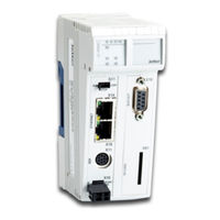
Jetter JetControl 365MC User Manual (148 pages)
Brand:
Jetter
| Category:
Controller
| Size: 4.16 MB
Table of Contents
Table of Contents
3
Introduction
7
Information on this Document
7
Typographical Conventions
7
Safety
8
General Information
8
Purpose
8
Intended Use
8
Usage Other than Intended
8
Warnings Used in this Document
9
Product Description
10
System Overview
10
Fig. 1 System Overview
10
Design
11
Product Features
11
Fig. 2 Design
11
Fig. 3 Status Indication
12
Diagnostics Capabilities by Means of Status Indication
12
Status Indication
12
LED States During the Boot Process
13
LED States after Detection of an IP Address Conflict
14
Tab. 1 LED States During the Boot Process
14
Nameplate
15
Scope of Delivery
15
Order Reference/Options
15
Fig. 4 Sample Nameplate
15
Fig. 5 Dimensions in MM
17
Dimensions
17
Technical Specifications
17
Mechanical Specifications
18
Tab. 2 Mechanical Specifications
18
Electrical Properties
19
Tab. 3 Power Supply (Terminal X10)
19
Tab. 4 Serial Interface (Port X11)
19
Tab. 5 Ethernet Interface (Ports X14, X15)
19
Tab. 6 CAN Bus Interface (Port X19)
19
Tab. 10 System Bus
20
Tab. 9 Electrical Safety
20
Tab. 8 Memory Configurations
20
Tab. 7 SD Card (Slot X61)
20
System Power Supply
20
Real-Time Clock
21
Environmental Conditions
21
Tab. 11 JX3 IO Modules on the System Bus
21
Tab. 13 Environmental Conditions
21
Tab. 16 Immunity of Shielded Data and I/O Lines
22
Tab. 15 Immunity to Interference
22
Tab. 14 Emitted Interference
22
Shielded Data and I/O Lines
22
Housing
22
EMI Values
22
DC Power Supply Inputs and Outputs
23
Tab. 17 DC Power Supply Inputs and Outputs
23
Mechanical Installation
24
Installing the Device on the DIN Rail
24
Fig. 6 Installing the Device on the DIN Rail
24
Removing the Device from the DIN Rail
25
Fig. 7 Removing the Device from the DIN Rail
25
Dismounting the Enclosure from the Backplane Module
26
Fig. 8 Dismounting the Enclosure from the Backplane Module
26
Electrical Connection
27
Improving the Noise Immunity
27
Fig. 9 Strain Relief on the Sub-D Housing
28
Ports and Interfaces
29
Selector Switch S11 - Mode Selector
29
Tab. 18 Switch Positions of Mode Selector S11
29
Terminal X10 - Power Supply
30
Tab. 19 Connector Specification, 2-Pin Connector, Spring-Cage Technology
30
Fig. 10 Schematic Diagram of Port X11
31
Port X11 - Serial Interface
31
Ports X14, X15 - Ethernet
32
Port X19 - CAN Bus
33
Fig. 11 Y-Cable (Splitter Cable) for the CAN Bus Interface
34
Tab. 20 JX2 System Bus Cable - Specification
35
Fig. 12 Connection Diagram of the System Bus Cable
36
Slot X61 - SD Memory Card
38
Commissioning
39
Configuring Error States
42
Configuration in Jetsym
43
Electronic Data Sheet (EDS)
45
Identification
45
Identification and Configuration
45
Tab. 21 Section [IDENTIFICATION]
46
Tab. 22 Section [PRODUCTION]
47
Tab. 23 Section [FEATURES]
47
Tab. 24 Register Numbers of the EDS
48
Version Registers
49
Tab. 25 Overview of EDS Registers
49
Tab. 26 Register Overview - Hardware Revisions
49
Tab. 27 Format of Software Version Numbers
50
Determining the IP Address of the Controller Using Jetipscan
51
Factory Settings
51
IP Configuration
51
Configuration Memory
53
Configuration File "Config.ini
54
Configuration Registers
58
Setting the IP Address
59
Fig. 15 Jetipscan - Command Options
61
Fig. 14 DIP Switch Sliders 1
63
Fig. 16 DIP Switch Sliders 1
63
Tab. 35 Name
67
Using Names for IP Addresses
67
Fig. 18 GNN DIP Switch Sliders
67
Fig. 17 DIP Switch Sliders 1
67
Operating System
69
Operating System Update of the Controller
69
Operating System Update of a JX2 or JX3 Module
71
File System
75
Properties
75
Programming
77
Abbreviations, Module Register Properties and Formats
77
File System Memory
78
Storage Options - Overview
78
Operating System Memory
78
Application Program Memory
79
Memory for Volatile Application Program Variables
80
Memory for Non-Volatile Application Program Registers
81
Memory for Non-Volatile Application Program Variables
82
Registers on I/O Modules
83
Memory for Non-Volatile Registers on the Backplane Module
84
Inputs and Outputs
85
Special Registers
85
Flag
87
Saving and Loading an Application Program
89
Addressing Expansion Modules
89
Numbering Registers and I/Os
90
Fig. 19 Example: Register Numbers
90
Fig. 20 Example: I/O Numbers
90
Fig. 21 System Overview
91
Fig. 22 Example: Register Numbers
92
Fig. 23 Example: I/O Numbers
92
Startup Delay Time
95
System Commands
95
Real-Time Clock
95
System Runtime Registers
96
Monitoring Interface Activities
96
Jetter Ethernet System Bus
97
Control of Alphanumeric Displays and Hmis
98
Controlling Printer and Serial Interfaces
98
Project Engineering of a JX2 Station
99
Project Engineering of a JX3 Station
99
JCF-SV1 "Simple Servo Function
100
E-Mail Feature
101
Modbus/Tcp
102
Modbus/Tcp Server
103
Modbus/Tcp Client with STX Functions
105
User-Programmable Serial Interface
107
User-Programmable IP Interface
107
User-Programmable CAN Interface
108
Canopen STX API
108
Motion Control
111
FTP Server
113
HTTP Server
114
FTP Client
115
Automatic Copying of Controller Data (Autocopy)
116
Registers - Overview
117
Fig. 13 Configuration
119
Tab. 12 Real-Time Clock
119
Maintenance and Repairs
140
Maintenance, Repairs and Disposal
140
Storage and Shipment
140
Service
141
Customer Service
141
List of Figures
145
Advertisement
Advertisement
Related Products
Jetter JetControl 340
Jetter JetControl 360
Jetter JetControl 360MC
Jetter JetControl 365
Jetter JetControlMobile 631
Jetter JetMove 3000
Jetter 60873049
Jetter 60873050
Jetter 60873051
Jetter JC-120MC
Jetter Categories
Control Unit
Controller
Amplifier
Computer Hardware
Recording Equipment
More Jetter Manuals
Login
Sign In
OR
Sign in with Facebook
Sign in with Google
Upload manual
Upload from disk
Upload from URL