Sign In
Upload
Manuals
Brands
Intel Manuals
Network Hardware
IXF1104
Intel IXF1104 Manuals
Manuals and User Guides for Intel IXF1104. We have
1
Intel IXF1104 manual available for free PDF download: Datasheet
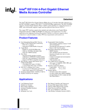
Intel IXF1104 Datasheet (231 pages)
4-Port Gigabit Ethernet Media Access Controller
Brand:
Intel
| Category:
Network Hardware
| Size: 3.34 MB
Table of Contents
Product Features
1
Table of Contents
3
0X00200000
13
Introduction
20
What You will Find in this Document
20
Related Documents
20
Revision Date: 27-Oct
20
General Description
21
Block Diagram
21
Internal Architecture
22
Ball Assignments and Ball List Tables
23
Ball Assignments
23
552-Ball CBGA Assignments (Top View)
23
Ball List in Alphanumeric Order by Ball Location
23
Ball List Tables
24
Balls Listed in Alphabetic Order by Signal Name
24
Ball List in Alphanumeric Order by Signal Name
24
Balls Listed in Alphabetic Order by Ball Location
30
Ball Assignments and Signal Descriptions
37
Naming Conventions
37
Signal Name Conventions
37
Register Address Conventions
37
Interface Signal Groups
38
Interface Signals
38
Signal Description Tables
39
SPI3 Interface Signal Descriptions
39
Document Number
39
Serdes Interface Signal Descriptions
47
GMII Interface Signal Descriptions
48
RGMII Interface Signal Descriptions
50
CPU Interface Signal Descriptions
51
Transmit Pause Control Interface Signal Descriptions
53
Optical Module Interface Signal Descriptions
53
MDIO Interface Signal Descriptions
54
LED Interface Signal Descriptions
55
JTAG Interface Signal Descriptions
55
System Interface Signal Descriptions
55
Power Supply Signal Descriptions
56
Ball Usage Summary
57
Multiplexed Ball Connections
58
Gmii/Rgmii/Serdes/Omi Multiplexed Ball Connections
58
Line Side Interface Multiplexed Balls
58
SPI3 MPHY/SPHY Ball Connections
59
SPI3 MPHY/SPHY Interface
59
Ball State During Reset
61
Definition of Output and Bi-Directional Balls During Hardware Reset
61
Power Supply Sequencing
63
Power-Down Sequence
63
Power-Up Sequence
63
Pull-Up/Pull-Down Ball Guidelines
64
Analog Power Filtering
64
Power Supply Sequencing
64
Pull-Up/Pull-Down and Unused Ball Guidelines
64
Analog Power Supply Filter Network
65
Analog Power Balls
65
Functional Descriptions
66
Media Access Controller (MAC)
66
Features for Fiber and Copper Mode
67
Automatic CRC Generation
67
Filtering of Receive Packets
67
Padding of Undersized Frames on Transmit
67
CRC Error Detection
69
Flow Control
69
CRC Errored Packets Drop Enable Behavior
69
Flow Control (Full-Duplex Operation)
70
Packet Buffering FIFO
71
Ethernet Frame Format
71
PAUSE Frame Format
72
Transmit Pause Control Interface
74
Valid Decodes for TXPAUSEADD[2:0]
74
Mixed-Mode Operation
75
Configuration
75
Key Configuration Registers
75
Fiber Mode
76
Operational Mode Configuration Registers
76
Document Number
76
Fiber Auto-Negotiation
77
Document Number
77
Determining if Link Is Established in Auto-Negotiation Mode
77
Fiber Forced Mode
77
Determination of Link Establishment in Forced Mode
77
Copper Mode
77
Speed
78
Duplex
78
Copper Auto-Negotiation
78
Jumbo Packet Support
78
Loss-Less Flow Control
79
Rx Statistics
79
TX Statistics
79
Packet Buffer Dimensions
80
TX and RX FIFO Operation
80
RMON Statistics Support
80
RMON Additional Statistics
81
Conventions
82
Advantages
83
SPI3 Interface
83
MPHY Operation
84
SPI3 RX Round Robin Data Transmission
84
MPHY Logical Timing
84
Receive Timing
85
Transmit Timing
85
MPHY Transmit Logical Timing
85
MPHY Receive Logical Timing
86
MPHY 32-Bit Interface
86
Clock Rates
87
Parity
87
SPHY Mode
87
Receive Timing (SPHY)
88
SPHY Logical Timing
88
Transmit Timing (SPHY)
88
SPHY Transmit Logical Timing
88
SPHY Receive Logical Timing
89
SPHY Connection for Two Intel ® IXF1104 MAC Ports (8-Bit Interface)
90
SPI3 Flow Control
91
Pre-Pending Function
93
Gigabit Media Independent Interface (GMII)
93
GMII Signal Multiplexing
94
GMII Interface Signal Definition
94
MAC GMII Interconnect
94
GMII Interface Signal Definitions
95
Reduced Gigabit Media Independent Interface (RGMII)
96
Multiplexing of Data and Control
96
RGMII Interface
96
Timing Specifics
97
TX_ER and RX_ER Coding
97
RGMII Signal Definitions
97
TX_ER and RX_ER Coding Description
97
RX_CTL Behavior
98
In-Band Status
99
TX_CTL Behavior
98
10/100 Mbps Functionality
99
MDIO Control and Interface
99
MDIO Address
100
MDIO Register Descriptions
100
Clear When Done
100
MDC Generation
100
MDC High-Frequency Operation
100
MDC Low-Frequency Operation
100
Management Frames
101
Single MDI Command Operation
101
MDI State Machine
101
Management Frame Structure (Single-Frame Format)
101
MDI State
102
Autoscan Operation
103
Serdes Interface
103
Features
103
Functional Description
103
Document Number
104
Serdes Driver TX Power Levels
104
Transmitter Operational Overview
104
Transmitter Programmable Driver-Power Levels
104
Receiver Jitter Tolerance
105
Receiver Operational Overview
105
Selective Power-Down
105
Receive Jitter
106
Transmit Jitter
106
Serdes Receiver Jitter Tolerance
106
Optical Module Interface
107
Intel® IXF1104 MAC-Supported Optical Module Interface Signals
107
Functional Descriptions
108
High-Speed Serial Interface
108
Low-Speed Status Signaling Interface
108
I 2 C Control and Data Registers
110
I 2 C Read Operation
110
I²C Module Configuration Interface
110
I 2 C Write Operation
111
C Random Read Transaction
111
I²C Protocol Specifics
112
Clock and Data Transitions
113
Port Protocol Operation
113
Data Validity Timing
113
Start and Stop Definition Timing
113
Acknowledge Timing
114
LED Interface
115
Modes of Operation
115
Random Read
115
LED Interface Signal Description
116
Mode 0: Detailed Operation
116
Mode 0 Timing
116
Mode 1: Detailed Operation
117
Mode 0 Clock Cycle to Data Bit Relationship
117
Power-On, Reset, Initialization
118
LED DATA Decodes
118
Mode 1 Timing
118
Mode 1 Clock Cycle to Data Bit Relationship
118
LED Signaling Behavior
119
LED_DATA# Decodes
119
LED Behavior (Fiber Mode)
119
CPU Interface
120
LED Behavior (Copper Mode)
120
Functional Description
121
Read Access
121
Write Access
121
Read Timing Diagram - Asynchronous Interface
121
CPU Timing Parameters
122
Endian
122
Write Timing Diagram - Asynchronous Interface
122
TAP Interface (JTAG)
123
TAP State Machine
123
Byte Swapper Behavior
123
Instruction Register and Supported Instructions
124
Instruction Register Description
124
ID Register
125
Boundary Scan Register
125
Bypass Register
125
Loopback Modes
125
SPI3 Interface Loopback
125
Line Side Interface Loopback
126
SPI3 Interface Loopback Path
126
Clocks
127
System Interface Reference Clocks
127
Line Side Interface Loopback Path
127
Clk125
128
MDC Clock
128
RGMII Clocks
128
SPI3 Receive and Transmit Clocks
128
I 2 C Clock
129
JTAG Clock
129
LED Clock
129
Contents
130
Applications
130
Change Port Mode Initialization Sequence
130
Disable and Enable Port Sequences
131
Disable Port Sequence
131
Enable Port Sequence
131
Electrical Specifications
132
Absolute Maximum Ratings
132
DC Specifications
133
Recommended Operating Conditions
133
Serdes Transmit Characteristics
134
DC Specifications
134
RGMII Electrical Characteristics
135
Undershoot / Overshoot Specifications
135
Serdes Receive Characteristics
135
Undershoot / Overshoot Limits
135
RGMII Power
136
SPI3 AC Timing Specifications
137
Receive Interface Timing
137
SPI3 Receive Interface Timing
137
SPI3 Receive Interface Signal Parameters
138
Transmit Interface Timing
139
SPI3 Transmit Interface Timing
139
SPI3 Transmit Interface Signal Parameters
140
RGMII AC Timing Specification
141
Contents
141
RGMII Interface Timing
141
RGMII Interface Timing Parameters
141
GMII AC Timing Specification
142
1000 Base-T Operation
142
1000 BASE-T Transmit Interface
142
1000BASE-T Transmit Interface Timing
142
GMII 1000BASE-T Transmit Signal Parameters
142
1000BASE-T Receive Interface
143
1000BASE-T Receive Interface Timing
143
GMII 1000BASE-T Receive Signal Parameters
143
Serdes AC Timing Specification
144
Serdes Timing Diagram
144
Serdes Timing Parameters
144
MDIO AC Timing Specification
145
MDC High-Speed Operation Timing
145
MDC Low-Speed Operation Timing
145
MDIO AC Timing
146
MDIO Write Timing Diagram
146
MDIO Read Timing Diagram
146
MDIO Timing Parameters
146
Optical Module and I 2 C AC Timing Specification
147
I 2 C Interface Timing
147
Bus Timing Diagram
147
Write Cycle Diagram
147
CPU AC Timing Specification
149
CPU Interface Read Cycle AC Timing
149
CPU Interface Write Cycle AC Timing
149
CPU Interface Write Cycle AC Signal Parameters
150
Transmit Pause Control AC Timing Specification
151
Pause Control Interface Timing
151
JTAG AC Timing Specification
152
JTAG AC Timing
152
JTAG AC Timing Parameters
152
System AC Timing Specification
153
System Reset AC Timing
153
System Reset AC Timing Parameters
153
LED AC Timing Specification
154
LED AC Interface Timing
154
LED Interface AC Timing Parameters
154
Register Set
155
Document Structure
155
Graphical Representation
155
Memory Overview Diagram
155
Per Port Registers
156
Register Map
156
Register Overview Diagram
156
MAC Control Registers ($ Port Index + Offset)
156
MAC RX Statistics Registers ($ Port Index + Offset)
157
MAC TX Statistics Registers ($ Port Index + Offset)
158
PHY Autoscan Registers ($ Port Index + Offset)
159
Global Status and Configuration Registers ($ 0X500 - 0X50C)
159
RX FIFO Registers ($ 0X580 - 0X5Bf)
159
TX FIFO Registers ($ 0X600 - 0X63E)
160
MDIO Registers ($ 0X680 - 0X683)
161
SPI3 Registers ($ 0X700 - 0X716)
161
Serdes Registers ($ 0X780 - 0X798)
162
Optical Module Registers ($ 0X799 - 0X79F)
162
MAC Control Registers
163
Station Address ($ Port_Index +0X00 – +0X01)
163
Desired Duplex ($ Port_Index + 0X02)
163
FD FC Type ($ Port_Index + 0X03)
163
Contents
164
Collision Distance ($ Port_Index + 0X05)
164
Collision Threshold ($ Port_Index + 0X06)
164
FC TX Timer Value ($ Port_Index + 0X07)
164
FD FC Address ($ Port_Index + 0X08 – + 0X09)
164
IPG Receive Time 1 ($ Port_Index + 0X0A)
165
IPG Receive Time 2 ($ Port_Index + 0X0B)
165
IPG Transmit Time ($ Port_Index + 0X0C)
165
Pause Threshold ($ Port_Index + 0X0E)
166
Max Frame Size (Addr: Port_Index + 0X0F)
166
MAC if Mode and RGMII Speed ($ Port_Index + 0X10)
167
Flush TX ($ Port_Index + 0X11)
167
FC Enable ($ Port_Index + 0X12)
168
FC Back Pressure Length ($ Port_Index + 0X13)
168
Short Runts Threshold ($ Port_Index + 0X14)
169
Discard Unknown Control Frame ($ Port_Index + 0X15)
169
RX Config Word ($ Port_Index + 0X16)
169
TX Config Word ($ Port_Index + 0X17)
170
Diverse Config Write ($ Port_Index + 0X18)
171
RX Packet Filter Control ($ Port_Index + 0X19)
172
Port Multicast Address ($ Port_Index +0X1A – +0X1B)
173
MAC RX Statistics Register Overview
174
MAC TX Statistics Register Overview
178
PHY Autoscan Registers
181
PHY Control ($ Port Index + 0X60)
181
PHY Status ($ Port Index + 0X61)
182
PHY Identification 1 ($ Port Index + 0X62)
183
PHY Identification 2 ($ Port Index + 0X63)
184
Auto-Negotiation Advertisement ($ Port Index + 0X64)
184
Auto-Negotiation Link Partner Base Page Ability ($ Port Index + 0X65)
185
Auto-Negotiation Expansion ($ Port Index + 0X66)
186
Auto-Negotiation Next Page Transmit ($ Port Index + 0X67)
187
Global Status and Configuration Register Overview
188
Port Enable ($0X500)
188
Interface Mode ($0X501)
188
Link LED Enable ($0X502)
189
MAC Soft Reset ($0X505)
189
MDIO Soft Reset ($0X506)
190
CPU Interface ($0X508)
190
LED Control ($0X509)
190
LED Flash Rate ($0X50A)
191
LED Fault Disable ($0X50B)
191
JTAG ID ($0X50C)
192
RX FIFO Register Overview
193
RX FIFO High Watermark Port 0 ($0X580)
193
RX FIFO High Watermark Port 1 ($0X581)
193
RX FIFO High Watermark Port 2 ($0X582)
193
RX FIFO High Watermark Port 3 ($0X583)
194
RX FIFO Low Watermark Port 0 ($0X58A)
194
RX FIFO Low Watermark Port 1 ($0X58B)
194
RX FIFO Low Watermark Port 2 ($0X58C)
195
RX FIFO Low Watermark Port 3 ($0X58D)
195
RX FIFO Overflow Frame Drop Counter Ports 0 - 3 ($0X594 – 0X597)
195
RX FIFO Port Reset ($0X59E)
196
RX FIFO Errored Frame Drop Enable ($0X59F)
196
RX FIFO Overflow Event ($0X5A0)
197
Document Number
197
RX FIFO Errored Frame Drop Counter Ports 0 - 3 ($0X5A2 - 0X5A5)
198
RX FIFO SPI3 Loopback Enable for Ports 0 - 3 ($0X5B2)
199
RX FIFO Padding and CRC Strip Enable ($0X5B3)
200
RX FIFO Transfer Threshold Port 0 ($0X5B8)
201
RX FIFO Transfer Threshold Port 1 ($0X5B9)
201
RX FIFO Transfer Threshold Port 2 ($0X5Ba)
202
RX FIFO Transfer Threshold Port 3 ($0X5Bb)
202
TX FIFO Register Overview
203
TX FIFO High Watermark Ports 0 - 3 ($0X600 – 0X603)
203
TX FIFO Low Watermark Register Ports 0 - 3 ($0X60A – 0X60D)
204
TX FIFO MAC Threshold Register Ports 0 - 3 ($0X614 – 0X617)
205
TX FIFO Overflow/Underflow/Out of Sequence Event ($0X61E)
206
Loop RX Data to TX FIFO (Line-Side Loopback) Ports 0 - 3 ($0X61F)
207
TX FIFO Port Reset ($0X620)
207
TX FIFO Overflow Frame Drop Counter Ports 0 - 3 ($0X621 – 0X624)
208
TX FIFO Errored Frame Drop Counter Ports 0 - 3 ($0X625 – 0X629)
209
TX FIFO Occupancy Counter for Ports 0 - 3 ($0X62D – 0X630)
210
TX FIFO Port Drop Enable ($0X63D)
210
MDIO Register Overview
211
MDIO Single Command ($0X680)
211
MDIO Single Read and Write Data ($0X681)
211
Autoscan PHY Address Enable ($0X682)
212
MDIO Control ($0X683)
212
SPI3 Register Overview
213
SPI3 Transmit and Global Configuration ($0X700)
213
SPI3 Receive Configuration ($0X701)
215
Address Parity Error Packet Drop Counter ($0X70A)
219
Serdes Register Overview
220
TX Driver Power Level Ports 0 - 3 ($0X784)
220
TX and RX Power-Down ($0X787)
220
RX Signal Detect Level Ports 0 - 3 ($0X793)
220
Clock and Interface Mode Change Enable Ports 0 - 3 ($0X794)
221
Optical Module Register Overview
222
Document Number
222
Optical Module Status Ports 0-3 ($0X799)
222
Optical Module Control Ports 0 - 3 ($0X79A)
222
Mechanical Specifications
224
Overview
224
Features
224
Package Specifics
224
Package Information
225
CBGA Package Diagrams
225
CBGA Package Diagram
225
CBGA Package Side View Diagram
226
Flip Chip-Plastic Ball Grid Array Package Diagram
227
FC-PBGA Package (Top and Bottom Views)
227
FC-PBGA Mechanical Specifications
228
Top Label Marking Example
229
Product Ordering Information
230
Product Information
230
Ordering Information – Sample
231
Advertisement
Advertisement
Related Products
Intel IXP45X
Intel IXP46X
Intel IXM5414E - Blade Server Ethernet Switch Module SBCEGBESW
Intel IXP400
Intel IXDP465
Intel IXP2800
Intel iX915GME
Intel IXP28 Series
Intel iX910GMLE-C6
Intel IXP28XX
Intel Categories
Motherboard
Computer Hardware
Server
Server Board
Desktop
More Intel Manuals
Login
Sign In
OR
Sign in with Facebook
Sign in with Google
Upload manual
Upload from disk
Upload from URL